Note: Descriptions are shown in the official language in which they were submitted.
COMPATIBLE LOW CRYSTALLINE SILICA SPACERS
BACKGROUND
[0001] Spacer fluids are often used in subterranean operations to facilitate
improved
displacement efficiency when introducing new fluids into a well bore. For
example, a spacer fluid
can be used to displace a fluid in a well bore before introduction of another
fluid. When used for
drilling fluid displacement, spacer fluids can enhance solids removal as well
as separate the drilling
fluid from a physically incompatible fluid. For instance, in primary cementing
operations, the
spacer fluid may be placed into the well bore to separate the cement
composition from the drilling
fluid. Spacer fluids may also be placed between different drilling fluids
during drilling change-
outs or between a drilling fluid and completion brine. Spacer fluids typically
do not consolidate in
that the spacer fluids typically do not develop significant gel or compressive
strength.
[0002] The spacer fluid can have certain characteristics to improve its
effectiveness. For
example, the spacer fluid may be compatible with the displaced fluid and the
cement composition.
This compatibility may also be present at downhole temperatures and pressures.
In some instances,
spacer fluids may be used to displace oil-based drilling fluids, often
referred to as "oil-based
muds," from a wellbore. Oil-based drilling fluids are typically an invert
emulsion that includes an
aqueous internal phase and an oil external phase. However, certain spacer
fluids may exhibit
negative interactions when contact and mixing occurs in the wellbore with the
oil-based drilling
fluids. This negative interaction may be referred to as "incompatibility" and
may be observed as a
significant increase in viscosity greater than either the viscosity of the
spacer fluid or the oil-based
drilling fluid.
BRIEF DESCRIPTION OF THE DRAWINGS
[0003] These drawings illustrate certain aspects of some of the embodiments of
the present
disclosure and should not be used to limit or define the present disclosure.
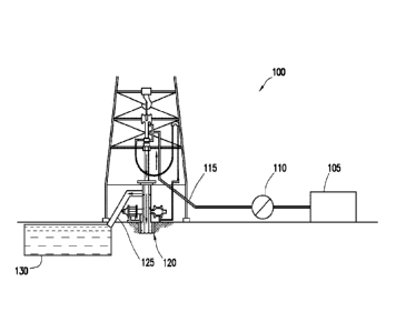
[0004] FIG. 1 is a schematic illustration of an example system for the
preparation and delivery
of a spacer fluid to a wellbore.
[0005] FIG. 2 is a schematic illustration of an example in which a spacer
fluid is used between
a cement composition and a drilling fluid.
[0006] FIG. 3 is a schematic illustration of the embodiment of FIG. 2 showing
displacement
of the drilling fluid.
1
Date Recue/Date Received 2022-10-12
SUMMARY
[0006a] In accordance with one aspect there is provided a method for
displacing wellbore
fluids, comprising: providing a spacer additive comprising: a biopolymer
comprising diutan gum;
and a scouring material selected from the group consisting of pumice, perlite,
fumed silica, and
combinations thereof, wherein the spacer additive comprises a spacer dry blend
of the biopolymer
and the scouring material, wherein the spacer dry blend has a diutan gum to
scouring material
weight ratio of about 2.4 to about 97.6, and wherein the spacer dry blend is
essentially free of
crystalline silica, preparing a spacer fluid by combining water and the spacer
additive, wherein the
spacer fluid is essentially free of clay; and introducing the spacer fluid
into a wellbore to displace
at least a portion of a first fluid in the wellbore.
[0006b] In accordance with another aspect there is provided a method for
displacing
wellbore fluids, comprising: providing a spacer dry blend comprising a spacer
additive, a solid
surfactant composite, and a weighting agent having a specific gravity greater
than 2.5, wherein the
spacer additive comprises pumice and diutan gum in a diutan gum to pumice
weight ratio of about
2.4 to about 97.6, and wherein the solid surfactant composite comprises a
surfactant on a solid
carrier; combining at least the spacer dry blend and water to form a spacer
fluid, wherein the spacer
fluid is essentially free of clay comprising montmorillonite clay, attapulgite
clay, and sepiolite
clay; and introducing the spacer fluid into a wellbore to displace at least a
portion of an oil-based
drilling fluid in the wellbore.
[0006c] In accordance with yet another aspect there is provided a method for
displacing
wellbore fluids, comprising: providing a spacer dry blend comprising: a
biopolymer comprising
diutan gum; a scouring agent comprising perlite; a solid surfactant composite;
and a weighting
agent comprising calcium carbonate, wherein the spacer dry blend has a
scleroglucan gum to
perlite weight ratio of about 2.4 to about 97.6; and combining at least the
spacer dry blend and
water to form a spacer fluid; introducing the spacer fluid into a wellbore to
displace at least a
portion of an oil-based drilling fluid in the wellbore.
DETAILED DESCRIPTION
la
Date Recue/Date Received 2022-10-12
CA 03122014 2021-06-03
WO 2020/159549 PCT/US2019/016402
[0007] The present disclosure relates to spacer fluids for use in subterranean
operations
and, more particularly, in certain embodiments, to spacer fluids that include
a spacer additive
comprising a solid scouring material and a biopolymer gum while being
essential free of clay. By
using the biopolymer gum instead of clay for viscosity, the spacer fluids may
have improved
compatibility with displaced fluids, such as oil-based drilling fluids. In
addition, the spacer fluids
may exhibit improved resistance to gelation upon contact with oil-based
drilling fluids in the well
bore, resulting in improved recovery of the oil-based drilling fluids and
reduced equivalent
circulating density. The spacer fluids may also include a solid surfactant
composite, for example,
that should also improve compatibility of the spacer fluid. The solid scouring
material used in the
spacer fluids may also be considered low crystalline silica (i.e., about 5 wt.
% or less). By using
solids scouring materials that are low crystalline silica, exposure of
personal crystalline silica may
be reduced, thus reducing or potentially limiting health hazards from
inhalation of silica particles.
In addition to the solid scouring material, biopolymer gum, and solid
surfactant, the spacer fluids
may further include defoaming agents and weighting agents as desired for a
particular application.
[0008] Embodiments may include preparing a spacer dry blend that includes a
spacer
additive and a solid surfactant composite, wherein the spacer additive
comprises a solid scouring
material and a biopolymer gum. The spacer dry blend may further include
optional additives,
including, defoaming agents and weighting agents. The spacer dry blend may be
prepared at any
suitable location. By way of example, the spacer dry blend may be prepared at
the well site or at
a remote location from the well site, such as a cement bulk plant. At the well
site, the spacer dry
blend may be combined with water, and the resulting spacer fluid may then be
pumped into the
wellbore. In other embodiments, one or more of spacer fluid components may be
individually
combined with the water at the well site to form the spacer fluid.
[0009] Embodiments of the spacer fluids may include spacer additive that
includes a solid
scouring material, for example, to scrub and facilitate removal of solid
filter cake on wellbore
surfaces. In some embodiments, suitable solid scouring materials may have a
Mohs hardness of
about 6 of greater. In some embodiments, suitable solid scouring materials may
have a high
angularity such that the solid scouring material has sharp and/or jagged
corners. By having sharp
and/or jagged corners, the solid scouring material may have improved scouring
with higher impact
pressures. Angularity and roundness are both terms that can be used to
describe the shape of the
corners on a particle. The higher the angularity of a particle (e.g., angular
particle), the lower the
roundness of that particle. Similarly, the higher the roundness of a particle,
the lower tile angularity
of that particle. As will be appreciated by one of skill in the art, and with
the help of this disclosure,
examples of suitable solid scouring materials may have high angularity. In
some embodiments,
2
CA 03122014 2021-06-03
WO 2020/159549 PCT/US2019/016402
suitable solid scouring materials may have roundness of less than about 0.6
and a sphericity less
than about 0.6. Roundness generally refers to the sharpness of the corners and
edges of a
grain/particle and it may be defined as the ratio of the average radius of
curvature of the corners
to the radius of the largest inscribed circle. Since can be quite time
consuming to measure
roundness, the common method of estimating roundness is to visually compare
grains of unknown
roundness with standard images of grains of known roundness. Sphericity
generally measures the
degree to which a particle approaches a spherical shape, and it may be defined
as the ratio between
the diameter of a sphere with the same volume as the particle and the diameter
of the circumscribed
sphere. The sphericity of a particle is usually determined by measuring the
three linear dimensions
of the particle: longest diameter, intermediate diameter and shortest
diameter.
[0010] In addition, the solid scouring material may be considered low
crystalline silica, in
that the solid scouring material may contain reduced amounts of crystalline
silica (i.e., about 5 wt.
0/0 or less). For example, the solid scouring material may contain crystalline
silica in an amount of
about 5 wt. % or less, about 3 wt.% or less, or about 1 wt.% or less. In some
embodiments, the
solid scouring material may be free and/or essentially free of crystalline
silica.
[0011] Examples of suitable solid scouring materials may include, but are not
limited to,
pumice, perlite, other volcanic glasses, fumed silica, and fly ash, among
others. In embodiments,
the solid scouring material may have a specific gravity of about 2.5 or less.
In some embodiments,
the solid scouring material may include pumice. Generally, pumice is a
volcanic rock that can
exhibit cementitious properties in that it may set and harden in the presence
of hydrated lime and
water. The pumice may also be ground. Generally, the pumice may have any
particle size
distribution as desired for a particular application. In certain embodiments,
the pumice may have
a mean particle size of about 1 micron to about 200 microns as defined by ASTM
methods. The
mean particle size corresponds to d50 values as measured by particle size
analyzers such as those
manufactured by Malvern Instruments, Worcestershire, United Kingdom. In
specific
embodiments, the pumice may have a mean particle size of from about 1 micron
to about 200
microns, from about 5 microns to about 100 microns, or from about 10 microns
to about 25
microns. The solid scouring material may be present in the spacer additive in
any suitable amount,
including, but not limited to, an amount of about 50 wt. 0/0 to about 99.9
wt.% based on a total
weight of the spacer additive. In specific embodiments, the solid scouring
material may be present
in an amount of about 90 wt. % to about 99 wt. % or from about 95 wt. % to
about 98 wt. % based
on a total weight of the spacer additive. In a specific example, the solid
scouring material may be
present in the spacer additive in an amount of about 97.6 wt. % based on a
total weight of the
3
CA 03122014 2021-06-03
WO 2020/159549 PCT/US2019/016402
spacer additive. One of ordinary skill in the art, with the benefit of this
disclosure, should be able
to select an appropriate particle size and concentration for the solid
scouring material.
[0012] Embodiments of the spacer fluids may include a spacer additive that
includes a
biopolymer gum. Examples of suitable biopolymer gums may include, but are not
limited to,
xanthan gum, diutan gum, welan gum, scleroglucan gum, and combinations
thereof. The
biopolymer gum may be present in the spacer additive in any suitable amount,
including, but not
limited to, an amount of about 0.1 wt. % to about 10 wt. % based on a total
weight of the spacer
additive. In specific embodiments, the solid scouring material may be present
in an amount of
about 1 wt. % to about 5 wt. % or from about 2 wt. 0/0 to about 3 wt. 0/0
based on a total weight of
the spacer additive. In a specific example, the biopolymer gum may be present
in the spacer
additive in an amount of about 97.6 wt. % based on a total weight of the
spacer additive. One of
ordinary skill in the art, with the benefit of this disclosure, should be able
to select an appropriate
concentration for the biopolymer.
[0013] The rheology and amount of solid scouring material and biopolymer gum
in the
spacer dry blend containing scouring agent, biopolymer gum, solid surfactant
composite,
defoaming agent, and/or weighting agent may be modified as desired to obtain a
spacer fluid with
desired properties. For example, reducing the weight percent of the biopolymer
gum in the spacer
dry blend should reduce the shear stress produced by the spacer fluid at a
given shear rate per unit
mass of spacer additive in the spacer dry blend. At low amounts such as 0.1
wt. % biopolymer
gum in the spacer additive achieving needed rheology in higher density spacer
fluids may be
hindered. If weight percent of the biopolymer gum in the spacer additive is
increased to an elevated
amount such as 10 wt. % or higher, the amount of solid scouring material may
be reduced to such
an extent that it becomes ineffective at scrubbing mud filter cake from the
wellbore. In some
embodiments, the spacer additive may have a biopolymer gum to solid scouring
material weight
ratio of about 0.5:99.5 to about 10:90 or about 1:99 to about 5:95 or from
about 2:98 to about
3:97. hi some embodiments, the biopolymer to solid scouring material weight
ratio may be about
2.4 biopolymer gum to about 97.6 solid scouring material.
[0014] The spacer additive may be included in the spacer dry blend in any
suitable amount.
In some embodiments, the spacer additive including the solid scouring material
and the
biopolymer gum may be included in the spacer dry blend in an amount of about
20 wt. % to about
100 wt. % based on a total weight of the spacer dry blend. In specific
embodiments, the spacer
dry blend may be present in an amount of about 20 wt. % to about 50 wt. %,
about 60 wt. % to
about 99 wt. %, about 80 wt. % to about 99 wt. %, or about 90 wt. % to about
100 wt. % based on
a total weight of the spacer dry blend.
4
CA 03122014 2021-06-03
WO 2020/159549 PCT/US2019/016402
[0015] Embodiments of the spacer fluids may include a solid surfactant
composite, which
may include a surfactant and a solid carrier. Optionally, the solid surfactant
composite may include
a dispersant, a defoaming agent, or a combination thereof. The solid
surfactant composite may
have a wide variety of shapes and sizes of individual particles suitable for
use in well applications.
By way of example, individual particles of the solid surfactant composite may
have well-defined
physical as well as irregular geometries, including the physical shape of
platelets, shavings, fibers,
flakes, ribbons, rods, strips, spheroids, hollow beads, toroids, pellets,
tablets, or any other physical
shape. Without limitation, the solid surfactant composite may have a mean
particle size in the
range of about 5 microns to about 1,500 microns and, alternatively, a mean
particle size in the
range of about 20 microns to about 500 microns, However, particle sizes
outside these defined
ranges also may be suitable for particular applications.
[0016] The solid surfactant composite may be included in the spacer dry blend
in any
suitable amount. In some embodiments, the solid surfactant composite may be
included in the
spacer dry blend in an amount of about 0.1 wt. % to about 10 wt. % based on a
total weight of the
spacer dry blend. In specific embodiments, the spacer dry blend may be present
in an amount of
about 1 wt. % to about 10 wt. %, about 1 wt. % to about 5 wt. %, or about 2
wt. % to about 5 wt.
% based on a total weight of the spacer dry blend.
[0017] Any of a variety of surfactants may be included in the solid surfactant
composite
that may be capable of wetting well surfaces (e.g., water- or oil-wetting),
such as the wellbore
wall and casing surface. The function that a particular surfactant may perform
depends on a variety
of factors. These factors may include, but are not limited to, the choice of
the hydrophobic and
hydrophilic portions and the relative amounts thereof and the presence of any
cationic, ionic, non-
ionic, amphoteric, or Zwitterionic groups. In some embodiments, both a water-
wetting surfactant
and an oil-wetting surfactant may be included in the solid surfactant
composite. The wetting
surfactant may be included in the solid surfactant composite in an amount,
without limitation, of
from about 5 wt. % to about 99.9 wt. % based on a total weight of the solid
surfactant composite.
By way of example, the wetting surfactant may be included in an amount of from
about 5 wt. %,
about 10 wt. %, about 20 wt. %, about 30 wt. %, about 40 wt. %, about 50 wt.
%, about 60 wt. %,
about 70 wt. %, about 80 wt. %, about 90 wt. %, or about 99.9 wt. % based on a
total weight of
the solid surfactant composite. Examples of suitable wetting surfactants may
include alcohol
ethoxylates, alcohol ethoxysulfates, alkyl phenol ethoxylates (e.g., nonyl
phenol ethoxylates),
glycol ethers, and combinations thereof. Certain of the wetting surfactants
may be used as water-
soluble salts. For example, the wetting surfactants may be selected from
alkali metal, alkaline
earth metal, ammonium, and alkanolammonium salts of alcohol ethoxylates,
alcohol
CA 03122014 2021-06-03
WO 2020/159549 PCT/US2019/016402
ethoxysulfates, and alkyl phenol ethoxylates. One of ordinary skill in the
art, with the benefit of
this disclosure, should be able to select an appropriate wetting surfactant
and concentration thereof
for a particular application.
[0018] As previously described, the wetting surfactant may be disposed on a
solid carrier.
Without limitation, the solid carrier may include any of a variety of solid
materials, such as
diatomaceous earth, amorphous silica, starch, calcium silicate, and
combinations thereof. The
solid carrier may be included in the solid surfactant composite in an amount,
without limitation,
of from about 0.1 wt. % to about 95 wt. % based on a total weight of the solid
surfactant composite.
By way of example, the solid carrier may be included in an amount of from
about 0.1 wt. %, about
wt. %, about 20 wt. %, about 30 wt. %, about 40 wt. %, about 50 wt. %, about
60 wt. %, about
70 wt. %, about 80 wt. %, about 90 wt. %, or about 95 wt. % based on a total
weight of the solid
surfactant composite. One of ordinary skill in the art, with the benefit of
this disclosure, should be
able to select an appropriate solid carrier and concentration thereof for a
particular application.
[0019] Optionally, the solid surfactant composite may include a dispersant.
Without
limitation, suitable dispersants may include any of a variety of commonly used
cement
dispersants, such as sulfonated dispersants; sulfonated polymer dispersants;
naphthalene
sulfonates; melamine sulfonates; sulfonated melamine formaldehyde condensate;
sulfonated
naphthalene formaldehyde condensate; sulfonate acetone formaldehyde
condensate; ethoxylated
polyacrylates; or combinations thereof. One example of a suitable dispersant
may include a
naphthalene sulfonate condensed with from about 4 moles to about 8 moles and,
alternatively,
about 6 moles of formaldehyde. The dispersant may be included in the solid
surfactant composite
in an amount, without limitation, of from about 10 wt. % to about 90 wt. %
based on a total weight
of the solid surfactant composite. By way of example, the dispersant may be
included in an amount
of from about 10 wt. %, about 20 wt. %, about 30 wt. %, about 40 wt. %, about
50 wt. %, about
60 wt. %, about 70 wt. %, about 80 wt. %, or about 90 wt. % based on a total
weight of the solid
surfactant composite. One of ordinary skill in the art, with the benefit of
this disclosure, should be
able to select an appropriate dispersant and concentration thereof for a
particular application.
[0020] Optionally, the solid surfactant composite may include a defoaming
agent. The
defoaming agent may be include in the solid surfactant composite in addition
to, or separate from,
the dispersant. Suitable defoaming agents may include compounds used in well
operations to
prevent a well treatment fluid from foaming during mixing and pumping. Without
limitation,
suitable defoaming agents may include polyol compositions, siloxanes such as
polydimethyl
siloxane, acetylenic diols, and combinations thereof. The defoaming agent may
be included in the
solid surfactant composite in addition to, or separate from, the dispersant.
The defoaming agent
6
CA 03122014 2021-06-03
WO 2020/159549 PCT/US2019/016402
may be included in the solid surfactant composite in an amount, without
limitation, of from about
0.1 wt. % to about 20 wt. % based on a total weight of the solid surfactant
composite. By way of
example, the defoaming agent may be included in an amount of from about 0.1
wt. %, about 5 wt.
%, about 10 wt. %, about 15 wt. %, or about 20 wt. % based on a total weight
of the solid surfactant
composite. One of ordinary skill in the art, with the benefit of this
disclosure, should be able to
select an appropriate defoaming agent and concentration thereof for a
particular application.
[0021] Without limitation, a solid surfactant composite may include an alcohol
ethoxylate,
a solid carrier including amorphous silica, a dispersant, and a defoaming
agent. By way of
example, the solid surfactant composite may include a C8 to C12 alcohol
substituted with about 4
moles to about 8 moles of ethylene oxide, amorphous silica, a sulfonated
naphthalene
formaldehyde condensate, and a siloxane. By way of further example, the solid
surfactant
composite may include isodecyl alcohol substituted with 6 moles of ethylene
oxide, amorphous
silica, naphthalene sulfonate condensed with 6 moles of formaldehyde, and a
polydimethyl
siloxane.
[0022] Without limitation, a solid surfactant composite may include an alcohol
ethoxylate,
a solid carrier, a dispersant, and a defoaming agent. By way of example, the
solid surfactant
composite may include a C12 to C14 alcohol substituted with about 10 moles to
about 14 moles of
ethylene oxide, amorphous silica, diatomaceous earth, a sulfonated naphthalene
formaldehyde
condensate, and a siloxane. By way of further example, the solid surfactant
composite may include
isotridecyl alcohol substituted with 12 moles ethylene oxide, amorphous
silica, diatomaceous
earth, naphthalene sulfonate condensed with 6 moles of formaldehyde, and a
polydimethyl
siloxane.
[0023] The solid stufactant composite may be prepared by any suitable
technique. By way
of example, the components (e.g., wetting surfactant, solid carrier,
dispersant, and/or defoarning
agent) may be combined to form a mixture. This mixture may then be dried, such
as by spray
drying, to form a substantially dry solid product. Other suitable techniques
for preparation of the
solid surfactant composite may also be used as should be apparent to one of
ordinary skill in the
art.
[0024] A wide variety of additional additives may be included in the spacer
dry blend as
deemed appropriate by one skilled in the art, with the benefit of this
disclosure. Examples of such
additives include but are not limited to: weighting agents (e.g., barite),
defoaming agents.
Weighting agents may be included in the spacer dry blend, for example, to
provide the spacer fluid
with a desired density. Examples of suitable weighting agents include, for
example, materials
having a specific gravity of 2.5 or greater, such as barite, manganese
tetraoxide, iron oxide,
7
CA 03122014 2021-06-03
WO 2020/159549 PCT/US2019/016402
calcium carbonate, or iron carbonate. Weighting agents may be included in any
suitable amount,
including, but not limited to, from about 1 wt. % to about 99 wt. %, about 50
wt. % to about 99
wt. %, or about 75 wt. % to about 99 wt. % based on a total weight of the
spacer dry blend.
Defoaming agents may be included in the spacer dry blend, for example, to
reduce undesirable
foaming in the spacer fluid upon mixing and instruction into the wellbore.
Examples of suitable
defoaming agents may include, but are not limited to, polyol compositions,
siloxanes such as
polydimethyl siloxane, acetylenic diols, ethoxylated alcohols, propoxylated
alcohols, fatty alcohol
ethoxylates, internal olefins and combinations thereof. Defoaming agents may
be included in any
suitable amount, including, but not limited to, from about 0.01 wt. % to about
10 wt. %, about
0.05 wt. % to about 5 wt. %, or about 0.05 wt. % to about 1 wt. % based on a
total weight of the
spacer dry blend. A person having ordinary skill in the art, with the benefit
of this disclosure,
should readily be able to determine the type and amount of additive useful for
a particular
application and desired result. While these additives are described as being
included in the spacer
dry blend, it is also contemplated that one or more of these additives may be
added directly to the
water, which may occur before, during, or after addition of the spacer dry
blend to the water.
[0025] As previously described, the spacer dry blend may be combined with
water to form
a spacer fluid, which may then be introduced into the wellbore. The water used
in an embodiment
of the spacer fluids may include, for example, freshwater, saltwater (e.g.,
water containing one or
more salts dissolved therein), brines, seawater, or any combination thereof.
Generally, the water
may be from any source, provided that the water does not contain an excess of
compounds that
may undesirably affect other components in the spacer fluid. The water is
included in an amount
sufficient to form a pumpable spacer fluid. In some embodiments, the water may
be included in
the spacer fluids in an amount in the range of from about 15 wt. % to about 95
wt. % based on a
total weight of the spacer fluid. In other embodiments, the water may be
included in the spacer
fluids in an amount in the range of from about 25 wt. % to about 85 wt. % or
about 50 wt. % to
about 75 wt. % based on a total weight of the spacer fluid. The spacer dry
blend may be included
in the spacer fluid in any suitable amount, including about 5 wt. % to about
50 wt. %, about 10
wt. % to about 60 wt. %, or about 20 wt. % to about 50 wt. % based on a total
weight of the spacer
fluid. One of ordinary skill in the art, with the benefit of this disclosure,
should recognize the
appropriate amount of water and spacer dry blend to include for a chosen
application.
[0026] In addition, the spacer fluids and/or spacer dry blends may be
considered low
crystalline silica, in that the spacer fluids and/or dry spacer fluids may
contain reduced amounts
of crystalline silica, not including any potential weighting agent (e.g.,
barite) that may be included.
For example, the spacer fluids and/or spacer dry blends may contain
crystalline silica in an amount
8
of about 5% or less, about 3% or less, or about 1% or less by weight. In some
embodiments, the
spacer fluids and/or spacer dry blends may be free and/or essentially free of
crystalline silica.
[0027] In addition, embodiments of the spacer fluids and/or spacer dry blends
may be
essentially free of clay in that they may contain no clay, or, to the extent
that clay may be present,
the clay is present in an amount of no more than 2 wt. %. In some embodiments,
the spacer fluids
may contain no clay, or, to the extent that clay may be present, the clay is
present in an amount of
no more than 1 wt. %, 0.5 wt. %, 0.1 wt. %, or less. A number of different
clays are commonly
included in spacer fluids and/or spacer dry blends, including, but not limited
to, montmorillonite
clays, attapulgite clays, and sepiolite clays. In contrast to conventional
spacers fluids that utilize
clay for viscosity, the spacer fluids comprising the spacer additive may use
the biopolymer gum
for viscosity. When clays are intercalated the platelets are stacked in layers
with ions between the
layers. As the clays exfoliate surfactants and ionic fluids with the mud often
interact unpredictably
with ionically charged platelets. This can result in gelation as well as lack
of appropriate viscous
properties. By reducing or potentially even eliminating clay from the spacer
fluids, the spacer fluid
may have increased compatibility with displaced or adjacent fluids.
[0028] The spacer fluids generally should have a density suitable for a
particular application as
desired by those of ordinary skill in the art, with the benefit of this
disclosure. In some embodiments, the
spacer fluids may have a density in the range of from about 4 pounds per
gallon ("lb/gal") (480 kg/m3) to
about 24 lgigal (2900 kg/m3). In other embodiments, the spacer fluids may have
a density in the range of
about 4 lb/gal (480 kg/m3) to about 17 lb/gal (2040 kg/m3). In yet other
embodiments, the spacer fluids may
have a density in the range of about 8 lg/gal (960 kg/m3) to about 13 lb/gal
(1600 kg/m3). Embodiments of
the spacer fluids may be foamed or unfoamed or include other means to reduce
their densities known in the
art, such as lightweight additives. Those of ordinary skill in the art, with
the benefit of this disclosure,
will recognize the appropriate density for a particular application.
[0029] Suitable spacer fluids may be prepared in accordance with any suitable
technique.
Without limitation, the desired quantity of water may be introduced into a
mixer (e.g., a cement
blender) followed by the spacer dry blend. Additional liquid additives and/or
dry additives, if any,
may be added to the water as desired prior to, or after, combination with the
dry blend. This mixture
may be agitated for a sufficient period of time to form a pumpable slurry. By
way of example,
pumps may be used for delivery of this pumpable slurry into the wellbore. As
will be appreciated,
the spacer fluid and/or the spacer dry blend may be prepared at the well site
or prepared offsite
and then transported to the well site. If prepared offsite, the spacer dry
blend and/or spacer fluid
may be transported to the well site using any suitable mode of transportation,
9
Date Recue/Date Received 2022-10-12
CA 03122014 2021-06-03
WO 2020/159549 PCT/US2019/016402
including, without limitation, a truck, railcar, barge, or the like.
Alternatively, the spacer fluid
and/or spacer dry blend may be formulated at the well site, for example, where
the components of
the spacer fluid and/or spacer dry blend may be delivered from a transport
(e.g., a vehicle or
pipeline) and then mixed prior to placement downhole. As will be appreciated
by those of ordinary
skill in the art, with the benefit of this disclosure, other suitable
techniques for preparing the spacer
fluids may be used in accordance with embodiments.
[0030] With limitation, the spacer fluid (as described herein) may be used for
displacing a
first fluid from a wellbore, the wellbore penetrating a subterranean
formation. The method may
further include introducing the spacer fluid into the wellbore to displace at
least a portion of the
first fluid from the wellbore. Without limitation, the spacer fluid may
displace the first fluid from
a wellbore annulus, such as the annulus between a pipe string and the
subterranean formation or
between the pipe string and a larger conduit. Non-limiting examples of the
first fluid displaced by
the spacer fluid may include a drilling fluid. By way of example, the spacer
fluid may be used to
displace the drilling fluid from the wellbore. In addition to displacement of
the drilling fluid from
the wellbore, the spacer fluid may also remove the drilling fluid from the
walls of the wellbore
and/or piper string. Additional steps in the method may include, without
limitation, introducing a
pipe string into the wellbore, introducing a cement composition into the
wellbore with the spacer
fluid separating the cement composition and the first fluid.
[0031] As described herein, the spacer fluid may prevent the cement
composition from
contacting the first fluid, such as a drilling fluid. The spacer fluid may
also remove the drilling
fluid, dehydrated/gelled drilling fluid, and/or filter cake solids from the
wellbore in advance of the
cement composition. Removal of these compositions from the wellbore may
enhance bonding of
the cement composition to surfaces in the wellbore.
[0032] The displaced drilling fluid may include, for example, any number of
fluids, such
as solid suspensions, mixtures, and emulsions. A non-limiting example of a
suitable drilling fluid
may include an oil-based drilling fluid. An example of a suitable oil-based
drilling fluid includes
an invert emulsion. Without limitation, the oil-based drilling fluid may
include an oleaginous
fluid. Examples of suitable oleaginous fluids that may be included in the oil-
based drilling fluids
include, but are not limited to, a-olefins, internal olefins, alkanes,
aromatic solvents, cycloalkanes,
liquefied petroleum gas, kerosene, diesel oils, crude oils, gas oils, fuel
oils, paraffin oils, mineral
oils, low-toxicity mineral oils, olefins, esters, amides, synthetic oils
(e.g., polyolefins),
polydiorganosiloxanes, siloxanes, organosiloxanes, ethers, dialkyl carbonates,
hydrocarbons, and
combinations thereof.
CA 03122014 2021-06-03
WO 2020/159549 PCT/US2019/016402
[0033] The cement composition introduced into the wellbore may include
hydraulic
cement and water. A variety of hydraulic cements may be utilized in accordance
with the present
embodiments, including, but not limited to, those including calcium, aluminum,
silicon, oxygen,
iron, and/or sulfur, which set and harden by reaction with water. Suitable
hydraulic cements
include, but are not limited to, Portland cements, pozzolana cements, gypsum
cements, high
alumina content cements, slag cements, silica cements, and combinations
thereof. In certain
embodiments, the hydraulic cement may include a Portland cement. In some
embodiments, the
Portland cements may include cements classified as Classes A, C, H, or G
cements according to
American Petroleum Institute, API Specification for Materials and Testing for
Well Cements, API
Specification 10, Fifth Ed., July 1, 1990. In addition, in some embodiments,
the hydraulic cement
may include cements classified as ASTM Type I, II, or III.
[0034] Without limitation, methods of using the spacer fluids described herein
in well
cementing will now be described in more detail with reference to FIGS. 1-3.
Any of the
embodiments of a spacer fluid described herein may apply in the context of
FIGS. 1-3. FIG. 1
illustrates an example system 100 that may be used for preparation and
delivery of a spacer fluid
downhole. It should be noted that while FIG. 1 generally depicts a land-based
operation, those
skilled in the art will readily recognize that the principles described herein
are equally applicable
to subsea operations that employ floating or sea-based platforms and rigs,
without departing from
the scope of the disclosure. As illustrated on FIG. 1, the system 100 may
include a vessel 105 and
a pump 110. The pump 110 may be positioned downstream of the vessel 105 and
may be fluidly
coupled to a tubular 115 that is in fluid communication with the wellbore 120.
The tubular 115
may be configured to circulate or otherwise deliver the spacer fluid to the
wellbore 120. The
tubular 115 may be comprised, for example, of one or more different pipes that
extend into the
wellbore 120. The pump 110 may be, for example, one or more high pressure or
low-pressure
pumps, which may be depend on, without limitation, the viscosity and density
of the spacer fluid.
Without limitation, the pump 110 may draw the spacer fluid from the vessel
105, elevate the spacer
fluid to an appropriate pressure, and then introduce the spacer fluid to the
tubular 115 for delivery
downhole. Without limitation, the vessel 105 and pump 110 may be disposed on
one or more
cement trucks, for example. While not illustrated, system 100 may further
include a recirculating
mixer, a batch mixer and/or a jet mixer, which may be used for example, in
preparation and/or
storage of the spacer fluid. Non-limiting additional components that may be
present include, but
are not limited to, supply hoppers, valves, condensers, adapters, joints,
gauges, sensors,
compressors, pressure controllers, pressure sensors, flow rate controllers,
flow rate sensors,
temperature sensors, and the like.
11
CA 03122014 2021-06-03
WO 2020/159549 PCT/US2019/016402
[0035] FIG. 2 depicts one or more subterranean formations 200 penetrated by
wellbore
120 with drilling fluid 205 disposed therein. The drilling fluid 205 may
include the example
drilling fluids disclosed herein as well as other suitable drilling fluids
that will be readily apparent
to those of ordinary skill in the art. While the wellbore 120 is shown
extending generally vertically
into the one or more subterranean formations 200, the principles described
herein are also
applicable to wellbores that extend at an angle through the one or more
subterranean formations
200, such as horizontal and slanted wellbores. As illustrated, the wellbore
120 includes walls 210.
Without limitation, a surface casing 215 may be cemented to the walls 210 of
the wellbore 120 by
cement sheath 220. Without limitation, one or more additional pipe strings
(e.g., intermediate
casing, production casing, liners, etc.), shown here as casing 225 may also be
disposed in the
wellbore 120. As illustrated, there is a wellbore annulus 230 formed between
the casing 225 and
the walls 210 of the wellbore 120 (and/or a larger conduit such as the surface
casing 215). While
not shown, one or more centralizers may be attached to the casing 225, for
example, to centralize
the casing 225 in the wellbore 120 prior to and during the cementing
operation.
[0036] As illustrated, a cement composition 235 may be introduced into the
wellbore 120.
For example, the cement composition 235 may be pumped down the interior of the
casing 225. A
pump (e.g. pump 110 on FIG. 1) may be used for delivery of the cement
composition 235 into the
wellbore 120. It may be desired to circulate the cement composition 235 in the
wellbore 120 until
it is in the wellbore annulus 230. The cement composition 235 may include the
example cement
compositions disclosed herein as well as other suitable cement compositions
that will be readily
apparent to those of ordinary skill in the art. While not illustrated, other
techniques may also be
utilized for introduction of the cement composition 235. By way of example,
reverse circulation
techniques may be used that include introducing the cement composition 235
into the wellbore
120 by way of the wellbore annulus 230 instead of through the casing 225.
[0037] Without limitation, the spacer fluid 240 may be used to separate the
drilling fluid
205 from the cement composition 235. The previous description with reference
to FIG. 1 for
preparation of a spacer fluid may be used for delivery of the spacer fluid 240
into the wellbore
120. Moreover, a pump (e.g., pump 110 on FIG. 1) may also be used for delivery
of the spacer
fluid 240 into the wellbore 120. The spacer fluid 240 may be used with the
cement composition
235 for displacement of the drilling fluid 205 from the wellbore 120 as well
as preparing the
wellbore 120 for the cement composition 235. By way of example, the spacer
fluid 240 may
function, inter alia, to remove the drilling fluid 205, drilling fluid 205
that is dehydrated/gelled,
and/or filter cake solids from the wellbore 120 in advance of the cement
composition 235. While
not shown, one or more plugs or other suitable devices may be used to
physically separate the
12
CA 03122014 2021-06-03
WO 2020/159549 PCT/US2019/016402
drilling fluid 205 from the spacer fluid 240 and/or the spacer fluid 240 from
the cement
composition 235.
[0038] Referring now to FIG, 3, the drilling fluid 205 has been displaced from
the wellbore
annulus 230. As illustrated, the spacer fluid 240 and the cement composition
235 may be allowed
to flow down the interior of the casing 225 through the bottom of the casing
225 (e.g., casing shoe
300) and up around the casing 225 into the wellbore annulus 230, thus
displacing the drilling fluid
205. At least a portion of the displaced drilling fluid 205 may exit the
wellbore annulus 230 via a
flow line 125 and be deposited, for example, in one or more retention pits 130
(e.g., a mud pit),
as shown in FIG. 1. Turning back to FIG. 3, the cement composition 235 may
continue to be
circulated until it has reached a desired location in the wellbore annulus
230. The spacer fluid 240
(or a portion thereof) and/or the cement composition 235 may be left in the
wellbore annulus 230.
As illustrated, the spacer fluid 240 may be disposed in the wellbore annulus
230 above or on top
of the cement composition 235. The cement composition 235 may set in the
wellbore annulus 230
to form an annular sheath of hardened, substantially impermeable material
(i.e., a cement sheath)
that may support and position the casing 225 in the wellbore 120.
[0039] Accordingly, this disclosure describes spacer fluids that include a
spacer additive
comprising a solid scouring material and a biopolymer gum while being
essential free of clay. The
systems and methods may further be characterized by one or more of the
following statements:
[0040] Statement 1. An example method may include spacer fluid include water
and a
spacer additive. The spacer additive may include a solid scouring material and
a biopolymer gum,
wherein the solid scouring material includes crystalline silica in an amount
of about 5 wt. % or
less, and wherein the spacer fluid is essentially free of clay. The example
method may further
include and introducing the spacer fluid into a wellbore to displace at least
a portion of a first fluid
in the wellbore.
[0041] Statement 2. The method of statement 1, further including combining at
least a
spacer dry blend and water to form the spacer fluid, wherein the spacer dry
blend includes the
solid scouring material and the biopolymer.
[0042] Statement 3. The method of statement 1 or 2, wherein the solid scouring
material
has a specific gravity of less than 2.5, and wherein the spacer fluid is free
of crystalline silica or
includes crystalline silica in an amount of about 1 wt. % or less, not
including any components
having a specific gravity greater than 2.5.
[0043] Statement 4. The method of any preceding statement, wherein the solid
scouring
material has a Mohs hardness of about 6 or greater, wherein the solid scouring
material has a
13
roundness of about 0.6 or less, and wherein the solid scouring material has a
sphericity of about
0.6 or less.
[0044] Statement 5. The method of any preceding statement, wherein the solid
scouring
material includes at least one material selected from the group consisting of
pumice, perlite, other
volcanic glasses, fumed silica, fly ash, and combinations thereof, and wherein
the biopolymer gum
includes at least one gum selected from the group consisting of xanthan gum,
diutan gum, welan
gum, scleroglucan gum, and combinations thereof.
[0045] Statement 6. The method of any preceding statement, wherein the solid
scouring
material includes pumice, and wherein the biopolymer gum includes diutan gum.
[0046] Statement 7. The method of any preceding statement, wherein a weight
ratio of the
biopolymer gum to the solid scouring material in the spacer additive is about
10:90 to about 1:99.
[0047] Statement 8. The method of any preceding statement, wherein a weight
ratio of the
biopolymer gum to the solid scouring material in the spacer additive is about
3:97 to about 2:98.
[0048] Statement 9. The method of any preceding statement, wherein the spacer
fluid
further includes a solid surfactant composite.
[0049] Statement 10. The method of statement 9, wherein the solid surfactant
composite
has a mean particle size of about 5 microns to about 1,500 microns, and
wherein the solid surfactant
composite includes a wetting surfactant on a solid carrier.
[0050] Statement 11. The method of any preceding statement, wherein the spacer
fluid
further includes at least one additive selected from the group consisting of a
defoaming agent, a
weighting agent, and combinations thereof.
[0051] Statement 12. The method of any preceding statement, wherein the first
fluid
includes an oil-based drilling fluid.
[0052] Statement 13. The method of any preceding statement, further including
introducing a cement composition into the wellbore behind the spacer fluid.
[0053] Statement 14. Another example may include a method for displacing
wellbore
fluids. The method may include providing a spacer dry blend that includes a
spacer additive, a
solid surfactant composite, and a weighting agent having a specific gravity
greater than 2.5,
wherein the spacer additive includes pumice and diutan gum in a diutan gum to
pumice weight
ratio of about 2:98 to about 3:97, and wherein the solid surfactant composite
includes a surfactant
on a solid carrier. The method may include combining at least the spacer dry
blend and water to
form a spacer fluid, wherein the spacer fluid is essentially free of clay
comprising montrnorillonite
14
Date Recue/Date Received 2022-10-12
clay, attapulgite clay, and sepiolite clay. The method may include introducing
the spacer fluid into
a wellbore to displace at least a portion of an oil-based drilling fluid in
the wellbore.
[0054] Statement 15. The method of statement 14, further including introducing
a cement
composition into the wellbore behind the spacer fluid.
[0055] Statement 16. An example spacer fluid for use in displacing wellbore
fluids may
include water and a spacer additive. The spacer additive may include a solid
scouring material and
a biopolymer gum, wherein the solid scouring material includes crystalline
silica in an amount of
about 2.5 wt. % or less, and wherein the spacer fluid is essentially free of
clay.
[0056] Statement 17. The spacer fluid of statement 16, wherein the solid
scouring material
has a specific gravity of less than 2.5, and wherein the spacer fluid is free
of crystalline silica or
includes crystalline silica in an amount of about 1 wt. % or less, not
including any components
having a specific gravity greater than 2.5.
[0057] Statement 18. The spacer fluid of statement 16 or 17, wherein the solid
scouring
material has a Mohs hardness of about 6 or greater, wherein the solid scouring
material has a
roundness of about 0.6 or less, and wherein the solid scouring material has a
sphericity of about
0.6 or less.
[0058] Statement 19. The spacer fluid of any one of statements 16 to 18,
wherein the solid
scouring material includes pumice, and wherein the biopolymer gum includes
diutan gum.
[0059] Statement 20. The spacer fluid of any one of statements 16 to 19,
wherein the
spacer fluid further includes a solid surfactant composite, wherein the solid
surfactant composite
includes a wetting surfactant on a solid carrier.
[0060] To facilitate a better understanding of the present disclosure, the
following
examples of certain aspects of some embodiments are given. In no way should
the following
examples be read to limit, or define, the scope of the disclosure. In the
following examples,
concentrations are given in weight percent of the overall composition.
EXAMPLE 1
[0061] A sample spacer fluid (Spacer 1) was prepared and evaluated for fluid
compatibility
with a first oil-based mud (0BM1). Spacer 1 had a density of 10.5 lbm/gal
(1260 kg/m3) and
composition provided in Table 1. Solid Surfactant Composite 1 included in
Spacer 1 was a water-
wetting surfactant (C6-C10 alcohol ethoxylate sulfate ammonium salt) disposed
on an amorphous
silica carrier. Solid Surfactant Composite 2 was an oil-wetting surfactant
(ethoxylated nonylphenol
blend) disposed on an amorphous silica carrier. OBM1 was a diesel-based invert
emulsion drilling mud.
Date Recue/Date Received 2022-10-12
CA 03122014 2021-06-03
WO 2020/159549 PCT/US2019/016402
[0062] Spacer 1 was evaluated for fluid compatibility with OBM1 at 80 F (27
C) and
180 F (82 C). Spacer 1 and OBM 1 were conditioned at the test temperature
for 30 minutes prior
to measurement. Ratios prescribed in API RP 10B2 (2013) were prepared, and
rheological
measurements were taken on Spacer 1, OBM1, and their mixtures using an OFITE
900 automated
viscometer having an R1-B1-F1 configuration. Dial readings from the viscometer
for the fluids
are shown at rotational speeds in Tables 2 and 3. Rotational speeds of 60
rotations per minute
(rpm) and 100 rpm are of key interest as they most closely approach shear
rates commonly
experienced during primary cementing. At 60 rpm and 100 rpm, none of the
mixtures experienced
adverse gelation or a dial reading greater than 10% of that of Spacer 1,
indicating good fluid
rheological compatibility for Spacer 1 and OBM1.
Table 1. Spacer 1 Composition
Material Mass, grams
Pumice 111.36
Diutan 2.74
Barite 210.28
Solid Surfactant Composite 1 6.85
Solid Surfactant Composite 2 6.85
Fresh Water 668.47
Table 2. Rheological Compatibility of Spacer 1 and OBM1 at 80 F.
Ratio of 300 rpm 200 rpm 100 rpm 60 rpm 30 rpm 6 rpm 3
rpm
OBM1 to
Spacer 1
100:0 22 17 10 8 6 2.8 2.5
95:75 25 18 11 8 6 2.8 2.5
75:25 35 24 13 10 7 2.6 2.1
50:50 48 38 24 18 12 5.1 3.5
25:75 47 40 31 24 17 7.6 5.5
5:95 48 42 37 31 24 14.8 11.6
16
CA 03122014 2021-06-03
WO 2020/159549 PCT/US2019/016402
0:100 46 42 38 36 32 26.6 21.8
Table 3. Rheological compatibility of Spacer 1 and OBM1 at 180 F.
Ratio of 300 200 100 60 rpm 30 rpm 6 rpm 3 rpm
OBM1 to rpm rpm rpm
Spacer 1
100:0 17 12 8 6 5 1.4 0.9
95:75 14 11 7 6 4 1.4 1.2
75:25 19 14 8 6 5 2.3 2.0
50:50 41 33 21 14 9 3.1 2.1
25:75 45 41 33 26 20 11.5 9.1
5:95 46 42 39 35 30 20.9 18.4
0:100 44 41 38 35 32 27.0 22.6
Example 2
[0063] ¨A second sample spacer fluid (Spacer 2) was prepared and evaluated for
fluid
compatibility with a second oil-based mud (OBM2). Spacer 2 had a density of
11.5 lbm/gal (1380
kg/m3) and composition provided in Table 4. Spacer 2 was evaluated for fluid
compatibility at 80
F (27 C) and 180 F (82 C) with OBM2. OBM2 was a diesel-based invert
emulsion drilling
mud. Spacer 2 and OBM2 were conditioned at the test temperature for 30 minutes
prior to
measurement. Ratios prescribed in API RP 10B2 (2013) were prepared, and
rheological
measurements were taken on Spacer 2, OBM2, and their mixtures using an OFITE
900 automated
viscometer having an R1-B1-F1 configuration. Dial readings from the viscometer
for the fluids
are shown at rotational speeds in Tables 5 and 6. Rotational speeds of 60 rpm
and 100 rpm are of
key interest as they most closely approach shear rates commonly experienced
during primary
cementing. At 60 rpm and 100 rpm none of the mixtures experienced adverse
gelation or a dial
reading greater than 10% of that of Spacer 2, indicating good fluid
rheological compatibility for
Spacer 2 and OBM2.
Table 4. Spacer 2 Composition
17
CA 03122014 2021-06-03
WO 2020/159549
PCT/US2019/016402
Material Mass, grams
Pumice 69.35
Diutan 1.71
Barite 356.98
Solid Surfactant Composite 1 6.85
Solid Surfactant Composite 2 6.85
Fresh Water 660.68
Table 5. Rheological Compatibility of Spacer 2 and OBM2 at 80 F.
Ratio of 300 200 100 60 rpm 30 rpm 6 rpm
3 rpm
OBM2 to rpm rpm rpm
Spacer 2
100:0 19 14 8 6 4 1.1 0.9
95:75 22 15 9 6 4 1.2 0.9
75:25 29 18 10 6 3 1.2 1.0
50:50 48 35 24 18 13 8.3 8.1
25:75 39 32 22 17 13 8.6 7.7
5:95 36 30 24 21 16 9.7 7.6
0:100 32 28 23 21 19 15.4 13.5
Table 6. Rheological Compatibility of Spacer 2 and OBM2 at 180 F.
Ratio of 300 200 100 60 rpm 30 rpm 6 rpm
3 rpm
OBM2 to rpm rpm rpm
Spacer 2
100:0 12 9 6 3 2 1.0 0.9
95:75 13 9 5 5 2 0.6 0.5
75:25 25 12 6 4 2 0.5 0.4
18
CA 03122014 2021-06-03
WO 2020/159549 PCT/US2019/016402
50:50 47 38 22 15 11 8.6 8.4
25:75 33 30 25 20 15 11.2 10.5
5:95 28 26 22 20 16 10.7 9.4
0:100 28 26 22 21 20 16.7 15.5
Example 3
[0064] A third sample spacer fluid (Spacer 3) was prepared and evaluated for
fluid
compatibility with a third oil-based mud (OBM3). Spacer 3 had a density of
11.5 lbm/gal (1380
kg/m3) and composition provided in Table 7. Spacer 3 was evaluated for fluid
compatibility at 80
F (27 C) and 180 F (82 C) with OBM3. OBM3 was a distillate-based invert
emulsion drilling
mud. Spacer 3 and OBM3 were conditioned at the test temperature for 30 minutes
prior to
measurement. Ratios prescribed in API RP 10B2 (2013) were prepared, and
rheological
measurements were taken on Spacer 3, OBM3, and their mixtures using an OFITE
900 automated
viscometer having an R1-B1-F1 configuration. Dial readings from the viscometer
for the fluids
are shown at rotational speeds in Tables 8 and 9. Rotational speeds of 60 rpm
and 100 rpm are of
key interest as they most closely approach shear rates commonly experienced
during primary
cementing. At 60 rpm and 100 rpm none of the mixtures experienced adverse
gelation or a dial
reading greater than 10% of that of Spacer 3, indicating good fluid
rheological compatibility for
Spacer 3 and OBM3.
Table 7. Spacer 3 Composition
Material Mass, grams
Pumice 74.91
Diutan 1.84
Barite 353.19
Solid Surfactant Composite 1 7.99
Solid Surfactant Composite 2 7.99
Fresh Water 656.48
Table 8. Rheological Compatibility of Spacer 3 and OBM3 at 80 F.
19
CA 03122014 2021-06-03
WO 2020/159549 PCT/US2019/016402
Ratio of 300 200 100 60 rpm 30 rpm 6 rpm 3
rpm
OBM3 to rpm rpm rpm
Spacer 3
100:0 12 9 5 4 4 1.4 1.2
95:75 12 8 5 3 2 0.7 0.6
75:25 14 10 7 5 3 0.6 0.4
50:50 32 24 15 10 6 3.2 3.0
25:75 34 29 22 18 12 5.3 4.1
5:95 38 32 26 22 18 10.8 9.6
0:100 35 31 26 23 21 16.9 14.9
Table 9. Rheological Compatibility of Spacer 3 and OBM3 at 180 F.
Ratio of OBM 300 200 100 60 rpm 30 rpm 6 rpm 3 rpm
to Spacer 3 rpm rpm rpm
100:0 8 6 4 3 3 1.0 0.9
95:75 8 6 3 3 1 1.0 0.9
75:25 9 7 3 2 1 0.9 0.9
50:50 29 22 15 11 7 4.9 4.8
25:75 21 27 23 19 14 8.7 8.1
5:95 33 30 26 24 20 13.8 12.3
0:100 31 29 25 23 22 18.1 16.1
Example 4
[0065] A fourth sample spacer fluid (Spacer 4) was prepared and evaluated for
fluid
compatibility with a cement slurry (CMT) having composition provided in Table
11. Spacer 4 had
a density of 11.5 lbm/gal (1380 kg/m') and composition provided in Table 10.
Spacer 4 was
evaluated for fluid compatibility at 80 F (27 C) and 180 F (82 C) with
CMT. Spacer 4 and
CMT were conditioned at the test temperature for 30 minutes prior to
measurement. Ratios
CA 03122014 2021-06-03
WO 2020/159549 PCT/US2019/016402
prescribed in API RP 10B2 (2013) were prepared, and rheological measurements
were taken on
Spacer 4, CMT, and their mixtures using an OFITE 900 automated viscometer
having an R1-B1-
Fl configuration. Dial readings from the viscometer for the fluids are shown
at rotational speeds
in Tables 12 and 13. Rotational speeds of 60 rpm and 100 rpm are of key
interest as they most
closely approach shear rates commonly experienced during primary cementing. At
60 rpm and
100 rpm none of the mixtures experienced adverse gelation or a dial reading
greater than 10% of
that of CMT, indicating good fluid rheological compatibility for Spacer 4 and
CMT.
Table 10. Spacer 4 Composition
Material Mass, grams
Pumice 74.91
Diutan 1.84
Barite 332.38
Solid Surfactant Composite 1 7.99
Solid Surfactant Composite 2 7.99
Fresh Water 677.29
Table 11. CMT Composition
Material Mass, grams
Type I/II Cement 440.47
Type F Fly Ash 174.91
Elastomer 36.14
Silica Fume 21.61
Fluid Loss Agent 1 3.07
Expansion Aid 24.62
Fresh Water 481.23
Table 12. Rheological Compatibility of Spacer 4 and CMT at 80 F.
21
CA 03122014 2021-06-03
WO 2020/159549 PCT/US2019/016402
Ratio of CMT 300 200 100 60 rpm 30 rpm 6 rpm 3 rpm
to Spacer 4 rpm rpm rpm
100:0 138 105 66 48 31 11.5 83
95:75 146 110 71 51 34 13.2 9.7
75:25 120 94 63 47 34 15.7 10,8
50:50 81 66 49 40 31 20.7 17.6
25:75 54 45 36 32 27 21.3 19.4
5:95 40 34 28 26 23 19.0 16.4
0:100 35 30 25 23 20 17.5 15.6
Table 13. Rheological Compatibility of Spacer 4 and CMT at 180 F.
Ratio of CMT 300 200 100 60 rpm 30 rpm 6 rpm 3 rpm
to Spacer 4 rpm r1)1P rpm
100:0 82 63 40 30 19 6.8 4.5
95:75 86 67 44 33 22 8.0 5.5
75:25 75 60 42 33 23 9.9 7.4
50:50 53 45 36 31 26 16.1 13.1
25:75 43 40 34 32 29 24.2 21,9
5:95 34 30 27 26 23 19.2 17.2
0:100 29 27 25 23 21 18.5 17.0
[0066] It should be understood that the compositions and methods are described
in terms
of "comprising," "containing," or "including" various components or steps, the
compositions and
methods can also "consist essentially of" or "consist of" the various
components and steps.
Moreover, the indefinite articles "a" or "an," as used in the claims, are
defined herein to mean one
or more than one of the element that it introduces.
[0067] For the sake of brevity, only certain ranges are explicitly disclosed
herein.
However, ranges from any lower limit may be combined with any upper limit to
recite a range not
explicitly recited, as well as, ranges from any lower limit may be combined
with any other lower
22
limit to recite a range not explicitly recited, in the same way, ranges from
any upper limit may be
combined with any other upper limit to recite a range not explicitly recited.
Additionally, whenever
a numerical range with a lower limit and an upper limit is disclosed, any
number and any included
range falling within the range are specifically disclosed. In particular,
every range of values (of the
form, "from about a to about b," or, equivalently, "from approximately a to
b," or, equivalently,
"from approximately a-b") disclosed herein is to be understood to set forth
every number and range
encompassed within the broader range of values even if not explicitly recited.
Thus, every point
or individual value may serve as its own lower or upper limit combined with
any other point or
individual value or any other lower or upper limit, to recite a range not
explicitly recited.
[0068] Therefore, the present disclosure is well adapted to attain the ends
and advantages
mentioned as well as those that are inherent therein. The particular
embodiments disclosed above
are illustrative only, as the present disclosure may be modified and practiced
in different manners
apparent to those skilled in the art having the benefit of the teachings
herein. Although individual
embodiments are discussed, the disclosure covers all combinations of all those
embodiments.
Furthermore, no limitations are intended to the details of construction or
design herein shown.
Also, the terms herein have their plain, ordinary meaning unless otherwise
explicitly and clearly
defined by the patentee. It is therefore evident that the particular
illustrative embodiments
disclosed above may be altered or modified and all such variations are
considered within the scope
of the present disclosure. If there is any conflict in the usages of a word or
term in this specification
and one or more patent(s) or other documents, the definitions that are
consistent with this
specification should be adopted.
23
Date Recue/Date Received 2022-10-12