Note: Descriptions are shown in the official language in which they were submitted.
CA 031034 2021--133
WO 2020/118258 PCT/US2019/065076
A Cannula and Proximally Mounted Camera with an Imaging
Control System for Rotating Images
Field of the Inventions
[0001] The inventions described below relate to the field
of minimally invasive surgery.
Background of the Inventions
[0002] U.S. Patent Application 15/239,632, entitled Cannula
with Proximally Mounted Camera (filed August 17, 2016)
discloses a cannula system with a proximally mounted camera,
operable to obtain images at the distal end of a cannula tube
with a camera located entirely proximally of the proximal edge
of the cannula tube. The camera (or a component of a camera
assembly) extends slightly into the cylindrical space defined
by the cannula tube and extending proximally from the cannula
tube, to overhang the lumen of the cannula tube, such that the
surgeon using the system camera may need to rotate the camera,
or the entire camera and cannula assembly, to make room for
surgical tubes otherwise impeded by the overhanging camera.
The system may be used for spine surgery, brain surgery or
other procedures.
Summary
[0003] The devices and methods described below provide for
improved visualization of body tissue during minimally
invasive surgery, including spine surgery and brain surgery.
The device comprises a cannula with a camera, or camera
component, mounted on the proximal end of the cannula with a
view into the cannula lumen and the tissue within and below
the lumen. A prism, reflector or other suitable optical
element oriented between the camera and the lumen of the
1
CA 031034 2021--133
WO 2020/118258 PCT/US2019/065076
cannula may be included to afford the camera a view into the
cannula while minimizing obstruction of the lumen. The camera
or optical element is small, relative to the cannula tube, so
that long, small diameter surgical tools may be inserted
through the cannula to locate the distal tip of the tools in a
surgical space at the distal end of the cannula. The system
includes means for adjusting the displayed image, to rotate
the displayed image to an initial preferred "natural"
orientation for the surgeon, regardless of the radial position
of the camera (if an initial placement does not provide a
display in a preferred orientation). The system also includes
means for tracking the radial position of the camera, relative
to the tube of the cannula or relative to an initial position
in space, and an imaging control system for rotating the
image, in response to rotation of the camera about the
proximal end of the cannula tube, to continue to present an
image of the surgical space in the initial preferred
orientation.
[0004] The system, and the method of access it enables, may
be used in minimally invasive surgery to provide an image of a
surgical space to a surgeon in an orientation preferred by the
surgeon while the surgeon is manipulating long surgical tools
within the cannula, and observing the workspace and tool tips
on a large display screen located near the patient. The
preferred orientation will most likely be (for a surgeon
standing vertically beside the patient) an orientation that
presents the image of the surgical space in a "natural" up-
down orientation from the surgeon's perspective, with the
portion of the surgical space furthest from the surgeon at the
top of the displayed image, the portion of the surgical space
nearest the surgeon at the bottom of the displayed image, the
portion of the surgical space at the surgeon's right displayed
at the right side of the displayed image, and the portion of
the surgical space at the surgeon's left displayed at the left
2
CA 031034 2021--133
WO 2020/118258 PCT/US2019/065076
side of the displayed image. The surgeon may place the
cannula in the patient, with the distal end of the cannula
proximate the surgical space, and with the camera at any
radial position relative to this natural up-down orientation,
and adjust the image using controls provided in the image
presentation system, to rotate the displayed image to match
the natural up-down orientation (or any other preferred
orientation). Thereafter, the surgeon may rotate the camera
(or the entire cannula and camera assembly) as necessary to
manipulate the tools disposed within the cannula tube, and the
image display system may be operated to sense the rotation of
the camera (or the entire cannula and camera assembly), and
"counter-rotate" the image to maintain the displayed image in
the natural up-down orientation (or any other preferred
orientation).
[0005] The system and method are illustrated in relation to
spinal surgery. The system and method may be used in brain
surgery and other surgeries.
Brief Description of the Drawings
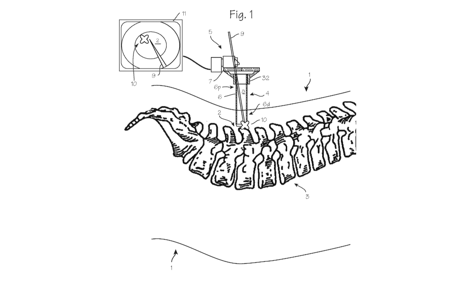
[0006] Figure 1 illustrates a patient with an area
requiring surgical intervention, and a cannula and camera
system installed through an incision to place the distal tip
of the cannula tube near the spine of the patient.
[0007] Figure 2 illustrates a cannula with a proximally
mounted camera.
[0008] Figure 3A, 3B and 3C illustrate the cannula and
camera system with sensors to operable to generate signals
corresponding to the radial position of the camera.
[0009] Figures 4, 5 and 6 depict exemplary images obtained
by the camera with an image in a first preferred orientation,
a disfavored rotated orientation, and a second preferred
3
CA 031034 2021--133
WO 2020/118258
PCT/US2019/065076
orientation image created by the image control system in
response to a determination of the change in radial position
of the camera.
Detailed Description of the Inventions
[0010]
Figure 1 illustrates a patient 1 with target tissue
2 proximate the spine 3 that necessitates surgical
intervention. A cannula 4 has been inserted through a
surgical opening, with the distal end of the cannula proximate
target tissue on the spine. The target tissue may be a
vertebral disc, bones of the spine, or other tissue or a
foreign object. A camera 5 is mounted on the proximal rim of
the cannula, with a portion of the camera overhanging the rim
of the cannula and disposed over the lumen of the cannula, and
is operable to obtain video or still images of the blood mass
or other tissue at the distal end of the cannula. The cannula
may comprise a cannula tube 6 and a mounting structure 7 may
be used to secure the camera to the proximal end 6p of the
cannula, to provide a view through the lumen 8 of the cannula
tube.
[0011] As
shown in Figure 1, a surgical tool 9 is disposed
within the cannula tube, in order to perform some operation on
some tissue portion 10 of the target tissue 2 within the
surgical space. This tissue might, for example, be a
protruding vertebral disc to be trimmed (a mini-discectomy),
or a portion of a pedicle or transverse process to be excised
or secured to implants, or a tumor or other diseased tissue to
be ablated or removed, etc. The image display system is
operated to display the image obtained by the camera, and
shows an image of the body tissue on the display screen in an
initial preferred orientation. (The image display system
comprises the display screen 11 and an image control system
operable to receive image signals from the camera, receive
position signals from the sensors, and transmit image data to
4
CA 03122084 2021-06-03
WO 2020/118258 PCT/US2019/065076
the display screen, rotated as directed by the user). In this
example, an image of the target tissue 2 appears within the
annular image of the inside wall of the cannula, and the
tissue portion 10 appears at the top of the screen, because it
is furthest from the surgeon and the surgeon has selected this
as the preferred initial orientation. An image of the
surgical tool 9 also appears on the display screen. However,
due to the position of the camera, the surgeon may not be able
to attack the tissue portion with full confidence, and may not
be able to clearly see the tissue to be approached due to the
presence of the proximal portions of the tool in the field of
view which block the view of the tissue portion 10 of concern.
To address this, the surgeon may rotate the camera about an
axis of the cannula tube (either by rotating the entire
cannula and camera assembly or rotating the camera about the
cannula tube, without rotating the camera tube). This
rotation is shown in Figure 2. Without correction, this
rotation will flip the displayed image, and the tissue portion
will appear at the bottom of the displayed image (and left
and right in the image will be reversed).
[0012] While it is possible to perform the surgical
procedure while viewing the surgical space upside down and
reversed, it is more natural, and thus safer, to operate on
the spine with the assistance of a consistent image display.
Accordingly, the image display system is operable to receive
signals corresponding to radial position and/or radial motion
from the position sensors associated with the camera,
determine an initial position relative to the cannula or an
absolute initial position in space based on those signals, and
thereafter determine the radial position of the camera vis-à-
vis a previously determined initial position relative to the
cannula or an absolute initial position in space, and generate
a "counter-rotated" image and display the counter-rotated
image on the display screen in the initial preferred
5
CA 031034 2021--133
WO 2020/118258 PCT/US2019/065076
orientation, so that the surgeon may operate, regardless of
camera position, on the basis of a displayed image which is
consistent throughout the procedure.
[0013] Figures 3A, 3B and 3C illustrate the cannula and
camera system with sensors operable to generate signals
corresponding to the radial position of the camera. As shown
in Figure 3A, 3B and 3C, the cannula 4 includes the components
shown in Figure 1 and 2, including the cannula tube 6 mounting
structure 7, and the system further includes the camera
assembly 5 with a component, such as a prism, a reflector or
other mirror structure or optical element 12, overhanging the
lumen of the cannula tube. The several views depict several
of the many sensors that may be used, in conjunction with the
image control system, to determine the radial position of the
camera relative to the cannula tube.
[0014] Figure 3A depicts a gyroscope or an accelerometer
assembly 13 (a single accelerometer, or a multi-axis axis
accelerometer assembly) radially fixed to the camera assembly.
The camera assembly in this embodiment may be rotatable on the
mounting structure, or radially fixed to the mounting
structure and/or cannula tube, or it may be rotatable relative
to the cannula tube, through the mounting ring which is
mounted on the end of the cannula tube using an annular snap
fitting and corresponding detent on the cannula tube, a
threaded fitting, a rotary union, or other means for rotatable
attachment.
[0015] The sensor is operable to provide a signal to the
image control system corresponding to motion of the camera
assembly, and the image control system is configured to
receive input from a user indicating that the camera is in a
first radial position (corresponding, for example, to an
initial orientation or an initial preferred orientation) and
display an image of the surgical field in a first orientation
6
CA 03122084 2021-06-03
WO 2020/118258 PCT/US2019/065076
corresponding to the first radial position on the display
screen, and thereafter receive signals corresponding to motion
of the camera assembly, and determine the radial position of
the camera relative to the first radial position, and, based
on this determination, rotate the image presented on the
display screen to present an image in the initial orientation
or an initial preferred orientation.
[0016] The sensor is operable to provide a signal to the
image control system corresponding to motion of the camera
assembly, and the image control system is configured to
receive input from a user indicating that the camera is in a
first radial position (corresponding, for example, to an
initial orientation or an initial preferred orientation) and
display an image of the surgical field in a first orientation
corresponding to the first radial position on the display
screen, and thereafter receive signals corresponding to motion
of the camera assembly, and determine the radial position of
the camera relative to the first radial position, and, based
on this determination, rotate the image presented on the
display screen to present an image in the initial orientation
or an initial preferred orientation.
[0017] Figure 3B depicts an encoder assembly (encoder scale
14A and a reader 14B) radially fixed to the camera assembly.
The camera assembly in this embodiment is rotatable on the
mounting structure, and the mounting structure is radially
fixed to the cannula tube. A first component of the encoder
assembly (an encoder reader) 14A is fixed to the camera, and a
second component of the encoder assembly (an encoder scale)
14B is fixed to the mounting structure.
[0018] The encoder assembly is operable to provide a signal
to the image control system corresponding to the position of
the camera assembly on the mounting structure, and the image
control system is configured to receive input from a user
7
CA 03122084 2021-06-03
WO 2020/118258
PCT/US2019/065076
indicating that the camera is in a first radial position
(corresponding, for example, to an initial orientation or an
initial preferred orientation) and display an image of the
surgical field in a first orientation corresponding to the
first radial position on the display screen, and thereafter
receive signals corresponding to a second position (or the
motion of the camera) of the camera assembly, and determine
the radial position of the camera relative to the first radial
position, and, based on this determination, rotate the image
presented on the display screen to present an image in the
initial orientation or the initial preferred orientation.
[0019]
Figure 3C depicts a neuronavigation marker array 15
radially fixed to the camera assembly. The camera assembly in
this embodiment may be rotatable on the mounting structure, or
radially fixed to the mounting structure and/or cannula tube.
The neuronavigation marker array is a first component of the
neuronavigation system 15A is fixed to the camera, and a
second component of the neuronavigation system (sensor(s)
operable to detect the markers, such as cameras, antennas,
ultrasound sensors, etc.) 15B is disposed proximate the marker
array.
[0020] The
neuronavigation system is operable to provide a
signal to the image control system corresponding to the
position of the camera assembly on the mounting structure, and
the image control system is configured to receive input from a
user indicating that the camera is in a first radial position
(corresponding, for example, to an initial orientation or an
initial preferred orientation) and display an image of the
surgical field in a first orientation corresponding to the
first radial position on the display screen, and thereafter
receive signals corresponding to a second position (or the
motion of the camera) of the camera assembly, and determine
the radial position of the camera relative to the first radial
position, and, based on this determination, rotate the image
8
CA 03122084 2021-06-03
WO 2020/118258
PCT/US2019/065076
presented on the display screen to present an image in the
initial orientation or the initial preferred orientation.
[0021] Generally, the image control system is configured to
receive input from a user indicating that the camera is in a
first radial position and display an image of the surgical
field in an initial orientation corresponding to the first
radial position on the display screen, and thereafter receive
signals from the sensors corresponding to the radial position
of the camera assembly, and determine the radial position of
the camera relative to the first radial position, and, based
on this determination, rotate the image presented on the
display screen to present an image in the initial orientation
or an initial preferred orientation. (The first radial
position can be defined by a geometric home position where the
camera may only be attached to the cannula in an initial
radial position or it may be initiated through the image
control system software user control setting a "home" or
"origin" starting position.)
[0022] The position sensors may be provided in many forms,
including the encoder operable to provide a signal
corresponding to the radial position of the camera relative to
the cannula tube, or other position counters (able to count
circular marks surrounding the top of the cannula) or color
arrays surrounding the cannula and interpreting the camera
position based on the software; a rheostat operable to provide
a signal corresponding to the radial position of the camera
relative to the tube; a gyroscope, operable to provide a
signal corresponding to motion of the camera about the plane
defined by the mounting structure or proximal edge of the
cannula tube (or a plane perpendicular to the long axis of the
cannula tube), which may be interpreted by the image control
system to determine radial displacement of the camera from an
initial position; an accelerometer assembly, operable to
provide a signal corresponding to radial motion of the camera
9
CA 031034 2021--133
WO 2020/118258
PCT/US2019/065076
about the plane defined by the mounting structure or proximal
edge of the cannula tube (or a plane perpendicular to the long
axis of the cannula tube), which may be interpreted by the
image control system to determine radial displacement of the
camera from an initial position; neuronavigation markers,
which, together with a neuronavigation system may provide a
signal corresponding to radial motion of the camera about the
cannula tube; a combination of accelerometers, gyroscopes and
gravitational sensors which are operable to provide signals
corresponding to absolute position and orientation of the
camera, which may be interpreted by the image control system
to determine radial displacement of the camera from an initial
position; and any other means for sensing the position of the
camera, or generating signals corresponding to the radial
position of the camera assembly, relative to an axis of the
cannula tube, either vis-a-vis a previously determined initial
position relative to the cannula or an absolute initial
position in space.
[0023]
Figures 4, 5 and 6 depict exemplary images obtained
by the camera with an image in a first preferred orientation,
a disfavored rotated orientation, and a second preferred
orientation image created by the image control system in
response to a determination of the change in radial position
of the camera. In Figure 4, the camera is in an initial
radial position, which in this case has been set by the
surgeon as a preferred orientation by providing input to the
image control system. The position of the camera and prism,
relative to the image, is shown in phantom. This image may be
(1) the image obtained by initial placement of the cannula,
including manual rotation of the camera or cannula, or (2)
software rotation of the image to present an image in the
preferred rotation. In this image of Figure 4, the camera is
located at the bottom of the screen (a default of the system;
the system may be configured to provide a default view of any
CA 031034 2021--133
WO 2020/118258 PCT/US2019/065076
orientation), and includes an image of target tissue 2,
surrounded by an annular image of the inside wall of the
cannula tube 6, with an image of the tissue portion 10 at the
upper left of the image (about 11:00 position) because the
tissue portion is opposite to the radial position of the
camera, which is at the 6:00 position. The tool 9 appears
extending down from the proximal end of the cannula, towards
the tissue portion 10. This image of the first preferred
orientation will be rotated if the surgeon rotates the camera
to move the camera out of its obstructing position (for
example, if the surgeon has rotated the cannula and camera
system about 1800). This rotation is shown in Figure 5, which
shows the tissue portion at the lower right, at about the 5:00
position, clockwise relative to the camera (which is now at
the top of the image, at the 12:00 position). With this
rotated image, the surgeon may have difficulty interpreting
the image. The image control system is operable, at the
selection of the surgeon, to rotate the image on the display
back to the initial preferred orientation, as shown in Figure
6. With this corrected display, the surgeon may manipulate
the tool to attack the tissue portion 10, using a display in
which the display is presented in the natural orientation,
with tissue furthest from the surgeon shown at the top of the
display and tissue closest to the surgeon shown at the bottom
of the screen.
[0024] In use, a surgeon will insert the distal end 6d of
the cannula tube into the body of a patient, through a
surgical opening (or a natural opening), to place the distal
end proximate the target tissue 2 and the tissue portion 10 to
be treated, inspected, etc. The surgeon will initially place
the camera at a convenient radial location relative to the
opening, the patient's position and the surgeon's stance. The
surgeon will provide input to the image control system through
an input means, indicating that this radial position is a
11
CA 03122084 2021-06-03
WO 2020/118258 PCT/US2019/065076
first radial position, and the image control system will then
display an image of the surgical field in an initial
orientation corresponding to the first radial position on the
display screen. If the surgeon is satisfied with this image,
the surgeon will provide input to the image control system
through an input means indicating that this is an initial
preferred orientation. If the surgeon prefers a different
initial preferred orientation, the surgeon may provide input
to the image control system to rotate the image (maintaining
the camera in its initial radial position) to a desired
initial preferred orientation, and provide input to the system
indicating that the resultant orientation of the image is the
initial preferred orientation. Thereafter, the surgeon may
operate the image control system to receive input from the
sensors which are indicative of the radial position of the
camera (vis-à-vis the initial position), and, when desired to
accommodate passage of tools, obtain a view otherwise blocked
by tools, etc., rotate the camera to a new position, and
operate the image control system to determine the extent of
the physical rotation of the camera about the axis of the
cannula, while operating the image control system to rotate
the displayed image to maintain the image in the preferred
initial orientation. In this description, the initial
orientation refers to the image obtained upon first placement
of the cannula. The initial preferred orientation is the
image that the surgeon prefers to work with, and uses the
system to set a desired up-down orientation. It could be
established by initial placement of the cannula (it could be
the initial orientation), or it could be established after
initial placement with the system rotating the image as
desired by the user to display the initial preferred
orientation on the display screen. All of the user input
described can be provide through an interface, such as a
dialog box in the onscreen interface, soft key provided on the
12
CA 03122084 2021-06-03
WO 2020/118258 PCT/US2019/065076
display along with a keyboard, or a physical switch or button
on the control system, or other input means.
[0025] The system need not know what the initial position
is or where it is in absolute terms: The operator may provide
input to the image control system to set, in the system, the
initial preferred orientation, and thus determine the sensor
reading corresponding to the initial preferred orientation.
The image control system then need only determine the radial
motion of the camera, vis-a-vis an initial position. For
example, using the accelerometer, the surgeon will provide
input to the image control system to set the initial preferred
orientation (after adjusting the cannula and camera, and
perhaps adjusting the image). The accelerometer readings
should be zero at this point, or taken as a starting point,
and the system need not determine the actual position of the
camera. Subsequent rotation of the camera about an axis of
the cannula tube will result in acceleration signals which are
used by the image control system to determine the amount of
rotation.
[0026] In embodiments where the image control system works
in cooperation with a neuronavigation system, which provides
absolute position relative to sensors of the neuronavigation
system, the image control system may rotate images vis-a-vis
an absolute position. Thus, the system may be operable to
determine, after registration of system sensors with the
patient, where the camera is and where it is pointed, and
determine its radial position, including determining the
initial radial position (when this is indicated with input
from an operator) and tracking the radial position of the
camera in space, rather than determining its rotation from an
initial starting position.
[0027] The initial preferred orientation may be obtained by
(1) initial placement and manual rotation of the cannula and
13
CA 031034 2021--133
WO 2020/118258 PCT/US2019/065076
camera assembly, rotating the cannula and camera assembly
prior to fixing it rotationally to the body or (2) initial
placement of the camera assembly without regard to orientation
of the camera to obtain an image in an initial orientation
(which may or may not be preferred) and subsequent operation
of the image control system to rotate the image data to
present an image in the initial preferred orientation on the
display screen.
[0028] The image control system, associated image
processing software and associated input devices provide means
for adjusting the displayed image and rotating the image to an
initial preferred orientation as described above. The various
sensor systems described in relation to Figures 3A, 3B and 3C
provide means for tracking the radial position of the camera.
The image control system and associated image processing
software provide means for presenting images obtained from the
camera assembly on the display in an initial preferred
orientation, and for rotating the image, in response to
rotation of the camera assembly radially relative to the
cannula tube, to continue to present an image of the surgical
space in the initial preferred orientation.
[0029] While the preferred embodiments of the devices and
methods have been described in reference to the environment in
which they were developed, they are merely illustrative of the
principles of the inventions. The devices may be used in
various intracerebral procedures such as intra-ventricular
hemorrhage procedures, neuro-stimulation procedures, and tumor
resection, and various spine surgeries such as decompression
and fusion procedures, and tumor resection. The elements of
the various embodiments may be incorporated into each of the
other species to obtain the benefits of those elements in
combination with such other species, and the various
beneficial features may be employed in embodiments alone or in
combination with each other. Other embodiments and
14
CA 03122084 2021-06-03
WO 2020/118258
PCT/US2019/065076
configurations may be devised without departing from the
spirit of the inventions and the scope of the appended claims.