Note: Descriptions are shown in the official language in which they were submitted.
CA 03122273 2021-06-04
WO 2020/123948
PCT/US2019/066242
SYSTEMS AND METHODS FOR A DEVICE USING A STATISTICAL
MODEL TRAINED ON ANNOTATED SIGNAL DATA
CROSS REFERENCE TO RELATED APPLICATIONS
This application claims priority under 35 U.S.C. 119(e) to U.S. Provisional
Application Serial No. 62/779,188, titled "NONINVASIVE NEUROLOGICAL
DISORDER TREATMENT MODALITY," filed December 13, 2018, U.S. Provisional
Application Serial No. 62/822,709, titled "SYSTEMS AND METHODS FOR A
WEARABLE DEVICE INCLUDING STIMULATION AND MONITORING
COMPONENTS," filed March 22, 2019, U.S. Provisional Application Serial No.
62/822,697, titled "SYSTEMS AND METHODS FOR A WEARABLE DEVICE FOR
SUBSTANTIALLY NON-DESTRUCTIVE ACOUSTIC STIMULATION," filed
March 22, 2019, U.S. Provisional Application Serial No. 62/822,684, titled
"SYSTEMS AND METHODS FOR A WEARABLE DEVICE FOR RANDOMIZED
ACOUSTIC STIMULATION," filed March 22, 2019, U.S. Provisional Application
Serial No. 62/822,679, titled "SYSTEMS AND METHODS FOR A WEARABLE
DEVICE FOR TREATING A NEUROLOGICAL DISORDER USING
ULTRASOUND STIMULATION," filed March 22, 2019, U.S. Provisional
Application Serial No. 62/822,675, titled "SYSTEMS AND METHODS FOR A
DEVICE FOR STEERING ACOUSTIC STIMULATION USING MACHINE
LEARNING," filed March 22, 2019, U.S. Provisional Application Serial No.
62/822,668, titled "SYSTEMS AND METHODS FOR A DEVICE USING A
STATISTICAL MODEL TRAINED ON ANNOTATED SIGNAL DATA," filed
March 22, 2019, and U.S. Provisional Application Serial No. 62/822,657, titled
"SYSTEMS AND METHODS FOR A DEVICE FOR ENERGY EFFICIENT
MONITORING OF THE BRAIN," filed March 22, 2019, all of which are hereby
incorporated herein by reference in their entireties.
BACKGROUND
Recent estimates by the World Health Organization (WHO) have placed
neurological disorders as constituting more than 6% of the global burden of
disease.
Such neurological disorders can include epilepsy, Alzheimer's disease, and
Parkinson's
disease. For example, about 65 million people worldwide suffer from epilepsy.
The
1
CA 03122273 2021-06-04
WO 2020/123948
PCT/US2019/066242
United States itself has about 3.4 million people suffering from epilepsy with
an
estimated $15 billion economic impact. These patients suffer from symptoms
such as
recurrent seizures, which are episodes of excessive and synchronized neural
activity in
the brain. Because more than 70% of epilepsy patients live with suboptimal
control of
their seizures, such symptoms can be challenging for patients in school, in
social and
employment situations, in everyday activities like driving, and even in
independent
living.
SUMMARY
In some aspects, a device wearable by or attached to or implanted within a
person includes a sensor configured to detect a signal from the brain of the
person and
a transducer configured to apply to the brain an acoustic signal.
In some embodiments, the sensor includes an electroencephalogram (EEG)
sensor, and the signal includes an EEG signal.
In some embodiments, the transducer includes an ultrasound transducer, and the
acoustic signal includes an ultrasound signal.
In some embodiments, the ultrasound signal has a frequency between 100 kHz
and 1 MHz, a spatial resolution between 0.001 cm3 and 0.1 cm3, and/or a power
density
between 1 and 100 watts/cm2 as measured by spatial-peak pulse-average
intensity.
In some embodiments, the ultrasound signal has a low power density, e.g.,
between 1 and 100 watts/cm2, and is substantially non-destructive with respect
to tissue
when applied to the brain.
In some embodiments, the sensor and the transducer are disposed on the head
of the person in a non-invasive manner.
In some embodiments, the device includes a processor in communication with
the sensor and the transducer. The processor is programmed to receive, from
the sensor,
the signal detected from the brain and transmit an instruction to the
transducer to apply
to the brain the acoustic signal.
In some embodiments, the processor is programmed to transmit the instruction
to the transducer to apply to the brain the acoustic signal at one or more
random
intervals.
In some embodiments, the device includes at least one other transducer
configured to apply to the brain an acoustic signal, and the processor is
programmed to
2
CA 03122273 2021-06-04
WO 2020/123948
PCT/US2019/066242
select one of the transducers to transmit the instruction to apply to the
brain the acoustic
signal at the one or more random intervals.
In some embodiments, the processor is programmed to analyze the signal to
determine whether the brain is exhibiting a symptom of a neurological disorder
and
transmit the instruction to the transducer to apply to the brain the acoustic
signal in
response to determining that the brain is exhibiting the symptom of the
neurological
disorder.
In some embodiments, the acoustic signal suppresses a symptom of a
neurological disorder.
In some embodiments, the neurological disorder includes one or more of stroke,
Parkinson's disease, migraine, tremors, frontotemporal dementia, traumatic
brain
injury, depression, anxiety, Alzheimer' s disease, dementia, multiple
sclerosis,
schizophrenia, brain damage, neurodegeneration, central nervous system (CNS)
disease, encephalopathy, Huntington' s disease, autism, attention deficit
hyperactivity
disorder (ADHD), amyotrophic lateral sclerosis (ALS), and concussion.
In some embodiments, the symptom includes a seizure.
In some embodiments, the signal includes an electrical signal, a mechanical
signal, an optical signal, and/or an infrared signal.
In some aspects, a method for operating a device wearable by or attached to or
implanted within a person, the device including a sensor configured to detect
a signal
from the brain of the person and a transducer configured to apply to the brain
an acoustic
signal, includes receiving, from the sensor, the signal detected from the
brain and
applying to the brain, with the transducer, the acoustic signal.
In some aspects, an apparatus includes a device worn by or attached to or
implanted within a person. The device includes a sensor configured to detect a
signal
from the brain of the person and a transducer configured to apply to the brain
an acoustic
signal.
In some aspects, a device wearable by a person includes a sensor configured to
detect a signal from the brain of the person and a transducer configured to
apply to the
brain an ultrasound signal. The ultrasound signal has a low power density,
e.g., between
1 and 100 watts/cm2, and is substantially non-destructive with respect to
tissue when
applied to the brain.
3
CA 03122273 2021-06-04
WO 2020/123948
PCT/US2019/066242
In some embodiments, the sensor and the transducer are disposed on the head
of the person in a non-invasive manner.
In some embodiments, the sensor includes an electroencephalogram (EEG)
sensor, and the signal includes an EEG signal.
In some embodiments, the transducer includes an ultrasound transducer.
In some embodiments, the ultrasound signal has a frequency between 100 kHz
and 1 MHz, a spatial resolution between 0.001 cm3 and 0.1 cm3, and/or the low
power
density between 1 and 100 watts/cm2 as measured by spatial-peak pulse-average
intensity.
In some embodiments, the ultrasound signal suppresses a symptom of a
neurological disorder.
In some embodiments, the neurological disorder includes one or more of stroke,
Parkinson's disease, migraine, tremors, frontotemporal dementia, traumatic
brain
injury, depression, anxiety, Alzheimer' s disease, dementia, multiple
sclerosis,
schizophrenia, brain damage, neurodegeneration, central nervous system (CNS)
disease, encephalopathy, Huntington' s disease, autism, attention deficit
hyperactivity
disorder (ADHD), amyotrophic lateral sclerosis (ALS), and concussion.
In some embodiments, the symptom includes a seizure.
In some embodiments, the signal includes an electrical signal, a mechanical
signal, an optical signal, and/or an infrared signal.
In some aspects, a method for operating a device wearable by a person, the
device including a sensor configured to detect a signal from the brain of the
person and
a transducer configured to apply to the brain an ultrasound signal, includes
applying to
the brain the ultrasound signal. The ultrasound signal has a low power
density, e.g.,
between 1 and 100 watts/cm2, and is substantially non-destructive with respect
to tissue
when applied to the brain.
In some aspects, a method includes applying to the brain of a person, by a
device
worn by or attached to the person, an ultrasound signal.
In some aspects, an apparatus includes a device worn by or attached to a
person.
The device includes a sensor configured to detect a signal from the brain of
the person
and a transducer configured to apply to the brain an ultrasound signal. The
ultrasound
signal has a low power density, e.g., between 1 and 100 watts/cm2, and is
substantially
non-destructive with respect to tissue when applied to the brain.
4
CA 03122273 2021-06-04
WO 2020/123948
PCT/US2019/066242
In some aspects, a device wearable by a person includes a transducer
configured
to apply to the brain of the person acoustic signals.
In some embodiments, the transducer is configured to apply to the brain of the
person acoustic signals randomly.
In some embodiments, the transducer includes an ultrasound transducer, and the
acoustic signals include an ultrasound signal.
In some embodiments, the ultrasound signal has a frequency between 100 kHz
and 1 MHz, a spatial resolution between 0.001 cm3 and 0.1 cm3, and/or a power
density
between 1 and 100 watts/cm2 as measured by spatial-peak pulse-average
intensity.
In some embodiments, the ultrasound signal has a low power density, e.g.,
between 1 and 100 watts/cm2, and is substantially non-destructive with respect
to tissue
when applied to the brain.
In some embodiments, the transducer is disposed on the head of the person in a
non-invasive manner.
In some embodiments, the acoustic signal suppresses a symptom of a
neurological disorder.
In some embodiments, the neurological disorder includes one or more of stroke,
Parkinson's disease, migraine, tremors, frontotemporal dementia, traumatic
brain
injury, depression, anxiety, Alzheimer' s disease, dementia, multiple
sclerosis,
schizophrenia, brain damage, neurodegeneration, central nervous system (CNS)
disease, encephalopathy, Huntington' s disease, autism, attention deficit
hyperactivity
disorder (ADHD), amyotrophic lateral sclerosis (ALS), and concussion.
In some embodiments, the symptom includes a seizure.
In some aspects, a method for operating a device wearable by a person, the
device including a transducer, includes applying to the brain of the person
acoustic
signals.
In some aspects, an apparatus includes a device worn by or attached to a
person.
The device includes a transducer configured to apply to the brain of the
person acoustic
signals.
In some aspects, a device wearable by or attached to or implanted within a
person includes a sensor configured to detect an electroencephalogram (EEG)
signal
from the brain of the person and a transducer configured to apply to the brain
a low
power, substantially non-destructive ultrasound signal.
CA 03122273 2021-06-04
WO 2020/123948
PCT/US2019/066242
In some embodiments, the ultrasound signal has a frequency between 100 kHz
and 1 MHz, a spatial resolution between 0.001 cm3 and 0.1 cm3, and/or a power
density
between 1 and 100 watts/cm2 as measured by spatial-peak pulse-average
intensity.
In some embodiments, the sensor and the transducer are disposed on the head
of the person in a non-invasive manner.
In some embodiments, the ultrasound signal suppresses an epileptic seizure.
In some embodiments, the device includes a processor in communication with
the sensor and the transducer. The processor is programmed to receive, from
the sensor,
the EEG signal detected from the brain and transmit an instruction to the
transducer to
apply to the brain the ultrasound signal.
In some embodiments, the processor is programmed to transmit the instruction
to the transducer to apply to the brain the ultrasound signal at one or more
random
intervals.
In some embodiments, the device includes at least one other transducer
configured to apply to the brain an ultrasound signal, and the processor is
programmed
to select one of the transducers to transmit the instruction to apply to the
brain the
ultrasound signal at the one or more random intervals.
In some embodiments, the processor is programmed to analyze the EEG signal
to determine whether the brain is exhibiting the epileptic seizure and
transmit the
instruction to the transducer to apply to the brain the ultrasound signal in
response to
determining that the brain is exhibiting the epileptic seizure.
In some aspects, a method for operating a device wearable by or attached to or
implanted within a person, the device including a sensor configured to detect
an
electroencephalogram (EEG) signal from the brain of the person and a
transducer
configured to apply to the brain a low power, substantially non-destructive
ultrasound
signal, includes receiving, by the sensor, the EEG signal and applying to the
brain, with
the transducer, the ultrasound signal.
In some aspects, an apparatus includes a device worn by or attached to or
implanted within a person. The device includes a sensor configured to detect
an
electroencephalogram (EEG) signal from the brain of the person and a
transducer
configured to apply to the brain a low power, substantially non-destructive
ultrasound
signal.
6
CA 03122273 2021-06-04
WO 2020/123948
PCT/US2019/066242
In some aspects, a device includes a sensor configured to detect a signal from
the brain of the person and a plurality of transducers, each configured to
apply to the
brain an acoustic signal. One of the plurality of transducers is selected
using a statistical
model trained on data from prior signals detected from the brain.
In some embodiments, the device includes a processor in communication with
the sensor and the plurality of transducers. The processor is programmed to
provide
data from a first signal detected from the brain as input to the trained
statistical model
to obtain an output indicating a first predicted strength of a symptom of a
neurological
disorder and, based on the first predicted strength of the symptom, select one
of the
plurality of transducers in a first direction to transmit a first instruction
to apply a first
acoustic signal.
In some embodiments, the processor is programmed to provide data from a
second signal detected from the brain as input to the trained statistical
model to obtain
an output indicating a second predicted strength of the symptom of the
neurological
disorder, in response to the second predicted strength being less than the
first predicted
strength, select one of the plurality of transducers in the first direction to
transmit a
second instruction to apply a second acoustic signal, and, in response to the
second
predicted strength being greater than the first predicted strength, select one
of the
plurality of transducers in a direction opposite to or different from the
first direction to
transmit the second instruction to apply the second acoustic signal.
In some embodiments, the statistical model comprises a deep learning network.
In some embodiments, the deep learning network comprises a Deep
Convolutional Neural Network (DCNN) for encoding the data onto an n-
dimensional
representation space and a ReCUITelit Neural Network (RNN) for computing a
detection
score by observing changes in the representation space through time. The
detection
score indicates a predicted strength of the symptom of the neurological
disorder.
In some embodiments, data from the prior signals detected from the brain is
accessed from an electronic health record of the person.
In some embodiments, the sensor includes an electroencephalogram (EEG)
sensor, and the signal includes an EEG signal.
In some embodiments, the transducer includes an ultrasound transducer, and the
acoustic signal includes an ultrasound signal.
7
CA 03122273 2021-06-04
WO 2020/123948
PCT/US2019/066242
In some embodiments, the ultrasound signal has a frequency between 100 kHz
and 1 MHz, a spatial resolution between 0.001 cm3 and 0.1 cm3, and/or a power
density
between 1 and 100 watts/cm2 as measured by spatial-peak pulse-average
intensity.
In some embodiments, the ultrasound signal has a low power density, e.g.,
between 1 and 100 watts/cm2, and is substantially non-destructive with respect
to tissue
when applied to the brain.
In some embodiments, the sensor and the transducer are disposed on the head
of the person in a non-invasive manner.
In some embodiments, the acoustic signal suppresses a symptom of a
neurological disorder.
In some embodiments, the neurological disorder includes one or more of stroke,
Parkinson's disease, migraine, tremors, frontotemporal dementia, traumatic
brain
injury, depression, anxiety, Alzheimer' s disease, dementia, multiple
sclerosis,
schizophrenia, brain damage, neurodegeneration, central nervous system (CNS)
disease, encephalopathy, Huntington' s disease, autism, attention deficit
hyperactivity
disorder (ADHD), amyotrophic lateral sclerosis (ALS), and concussion.
In some embodiments, the symptom includes a seizure.
In some embodiments, the signal includes an electrical signal, a mechanical
signal, an optical signal, and/or an infrared signal.
In some aspects, a method for operating a device, the device including a
sensor
configured to detect a signal from the brain of the person and a plurality of
transducers,
each configured to apply to the brain an acoustic signal, includes selecting
one of the
plurality of transducers using a statistical model trained on data from prior
signals
detected from the brain.
In some aspects, an apparatus includes a device that includes a sensor
configured to detect a signal from the brain of the person and a plurality of
transducers,
each configured to apply to the brain an acoustic signal. The device is
configured to
select one of the plurality of transducers using a statistical model trained
on data from
prior signals detected from the brain.
In some aspects, a device includes a sensor configured to detect a signal from
the brain of the person and a plurality of transducers, each configured to
apply to the
brain an acoustic signal. One of the plurality of transducers is selected
using a statistical
8
CA 03122273 2021-06-04
WO 2020/123948
PCT/US2019/066242
model trained on signal data annotated with one or more values relating to
identifying
a health condition.
In some embodiments, the signal data annotated with the one or more values
relating to identifying the health condition comprises the signal data
annotated with
respective values relating to increasing strength of a symptom of a
neurological
disorder.
In some embodiments, the statistical model was trained on data from prior
signals detected from the brain annotated with the respective values between 0
and 1
relating to increasing strength of the symptom of the neurological disorder.
In some embodiments, the statistical model includes a loss function having a
regularization term that is proportional to a variation of outputs of the
statistical model,
an L1/L2 norm of a derivative of the outputs, or an L1/L2 norm of a second
derivative
of the outputs.
In some embodiments, the device includes a processor in communication with
the sensor and the plurality of transducers. The processor is programmed to
provide
data from a first signal detected from the brain as input to the trained
statistical model
to obtain an output indicating a first predicted strength of the symptom of
the
neurological disorder and, based on the first predicted strength of the
symptom, select
one of the plurality of transducers in a first direction to transmit a first
instruction to
apply a first acoustic signal.
In some embodiments, the processor is programmed to provide data from a
second signal detected from the brain as input to the trained statistical
model to obtain
an output indicating a second predicted strength of the symptom of the
neurological
disorder, in response to the second predicted strength being less than the
first predicted
strength, select one of the plurality of transducers in the first direction to
transmit a
second instruction to apply a second acoustic signal, and, in response to the
second
predicted strength being greater than the first predicted strength, select one
of the
plurality of transducers in a direction opposite to or different from the
first direction to
transmit the second instruction to apply the second acoustic signal.
In some embodiments, the trained statistical model comprises a deep learning
network.
In some embodiments, the deep learning network comprises a Deep
Convolutional Neural Network (DCNN) for encoding the data onto an n-
dimensional
9
CA 03122273 2021-06-04
WO 2020/123948
PCT/US2019/066242
representation space and a Recurrent Neural Network (RNN) for computing a
detection
score by observing changes in the representation space through time. The
detection
score indicates a predicted strength of the symptom of the neurological
disorder.
In some embodiments, the signal data includes data from prior signals detected
from the brain that is accessed from an electronic health record of the
person.
In some embodiments, the sensor includes an electroencephalogram (EEG)
sensor, and the signal includes an EEG signal.
In some embodiments, the transducer includes an ultrasound transducer, and the
acoustic signal includes an ultrasound signal.
In some embodiments, the ultrasound signal has a frequency between 100 kHz
and 1 MHz, a spatial resolution between 0.001 cm3 and 0.1 cm3, and/or a power
density
between 1 and 100 watts/cm2 as measured by spatial-peak pulse-average
intensity.
In some embodiments, the ultrasound signal has a low power density, e.g.,
between 1 and 100 watts/cm2, and is substantially non-destructive with respect
to tissue
when applied to the brain.
In some embodiments, the sensor and the transducer are disposed on the head
of the person in a non-invasive manner.
In some embodiments, the acoustic signal suppresses the symptom of the
neurological disorder.
In some embodiments, the neurological disorder includes one or more of stroke,
Parkinson's disease, migraine, tremors, frontotemporal dementia, traumatic
brain
injury, depression, anxiety, Alzheimer' s disease, dementia, multiple
sclerosis,
schizophrenia, brain damage, neurodegeneration, central nervous system (CNS)
disease, encephalopathy, Huntington' s disease, autism, attention deficit
hyperactivity
disorder (ADHD), amyotrophic lateral sclerosis (ALS), and concussion.
In some embodiments, the symptom includes a seizure.
In some embodiments, the signal includes an electrical signal, a mechanical
signal, an optical signal, and/or an infrared signal.
In some aspects, a method for operating a device, the device including a
sensor
configured to detect a signal from the brain of the person and a plurality of
transducers,
each configured to apply to the brain an acoustic signal, includes selecting
one of the
plurality of transducers using a statistical model trained on signal data
annotated with
one or more values relating to identifying a health condition.
CA 03122273 2021-06-04
WO 2020/123948
PCT/US2019/066242
In some aspects, an apparatus includes a device that includes a sensor
configured to detect a signal from the brain of the person and a plurality of
transducers,
each configured to apply to the brain an acoustic signal. The device is
configured to
select one of the plurality of transducers using a statistical model trained
on signal data
annotated with one or more values relating to identifying a health condition.
In some aspects, a device includes a sensor configured to detect a signal from
the brain of the person and a first processor in communication with the
sensor. The
first processor is programmed to identify a health condition and, based on the
identified
health condition, provide data from the signal to a second processor outside
the device
to corroborate or contradict the identified health condition.
In some embodiments, identifying the health condition comprises predicting a
strength of a symptom of a neurological disorder.
In some embodiments, the processor is programmed to provide data from the
signal detected from the brain as input to a first trained statistical model
to obtain an
output indicating the predicted strength, determine whether the predicted
strength
exceeds a threshold indicating presence of the symptom, and, in response to
the
predicted strength exceeding the threshold, transmit data from the signal to a
second
processor outside the device.
In some embodiments, the first statistical model was trained on data from
prior
signals detected from the brain.
In some embodiments, the first trained statistical model is trained to have
high
sensitivity and low specificity, and the first processor using the first
trained statistical
model uses a smaller amount of power than the first processor using the second
trained
statistical model.
In some embodiments, the second processor is programmed to provide data
from the signal to a second trained statistical model to obtain an output to
corroborate
or contradict the predicted strength.
In some embodiments, the second trained statistical model is trained to have
high sensitivity and high specificity.
In some embodiments, the first trained statistical model and/or the second
trained statistical model comprise a deep learning network.
In some embodiments, the deep learning network comprises a Deep
Convolutional Neural Network (DCNN) for encoding the data onto an n-
dimensional
11
CA 03122273 2021-06-04
WO 2020/123948
PCT/US2019/066242
representation space and a Recurrent Neural Network (RNN) for computing a
detection
score by observing changes in the representation space through time. The
detection
score indicates a predicted strength of the symptom of the neurological
disorder.
In some embodiments, the sensor includes an electroencephalogram (EEG)
sensor, and the signal includes an EEG signal.
In some embodiments, the sensor is disposed on the head of the person in a non-
invasive manner.
In some embodiments, the neurological disorder includes one or more of stroke,
Parkinson's disease, migraine, tremors, frontotemporal dementia, traumatic
brain
injury, depression, anxiety, Alzheimer' s disease, dementia, multiple
sclerosis,
schizophrenia, brain damage, neurodegeneration, central nervous system (CNS)
disease, encephalopathy, Huntington' s disease, autism, attention deficit
hyperactivity
disorder (ADHD), amyotrophic lateral sclerosis (ALS), and concussion.
In some embodiments, the symptom includes a seizure.
In some embodiments, the signal includes an electrical signal, a mechanical
signal, an optical signal, and/or an infrared signal.
In some aspects, a method for operating a device, the device including a
sensor
configured to detect a signal from the brain of the person and a transducer
configured
to apply to the brain an acoustic signal, includes identifying a health
condition and,
based on the identified health condition, providing data from the signal to a
second
processor outside the device to corroborate or contradict the identified
health condition.
In some aspects, an apparatus includes a device that includes a sensor
configured to detect a signal from the brain of the person and a transducer
configured
to apply to the brain an acoustic signal. The device is configured to identify
a health
condition and, based on the identified health condition, provide data from the
signal to
a second processor outside the device to corroborate or contradict the
identified health
condition.
It should be appreciated that all combinations of the foregoing concepts and
additional concepts discussed in greater detail below (provided such concepts
are not
mutually inconsistent) are contemplated as being part of the inventive subject
matter
disclosed herein. In particular, all combinations of claimed subject matter
appearing at
the end of this disclosure are contemplated as being part of the inventive
subject matter
disclosed herein.
12
CA 03122273 2021-06-04
WO 2020/123948
PCT/US2019/066242
BRIEF DESCRIPTION OF THE DRAWINGS
Various aspects and embodiments will be described with reference to the
following figures. The figures are not necessarily drawn to scale.
FIG. 1 shows a device wearable by a person, e.g., for treating a symptom of a
neurological disorder, in accordance with some embodiments of the technology
described herein.
FIGs. 2A-2B show illustrative examples of a device wearable by a person for
treating a symptom of a neurological disorder and mobile device(s) executing
an
application in communication with the device, in accordance with some
embodiments
of the technology described herein.
FIG. 3A shows an illustrative example of a mobile device and/or a cloud server
in communication with a device wearable by a person for treating a symptom of
a
neurological disorder, in accordance with some embodiments of the technology
described herein.
FIG. 3B shows a block diagram of a mobile device and/or a cloud server in
communication with a device wearable by a person for treating a symptom of a
neurological disorder, in accordance with some embodiments of the technology
described herein.
FIG. 4 shows a block diagram for a wearable device including stimulation and
monitoring components, in accordance with some embodiments of the technology
described herein.
FIG. 5 shows a block diagram for a wearable device for substantially non-
destructive acoustic stimulation, in accordance with some embodiments of the
technology described herein.
FIG. 6 shows a block diagram for a wearable device for acoustic stimulation,
e.g., randomized acoustic stimulation, in accordance with some embodiments of
the
technology described herein.
FIG. 7 shows a block diagram for a wearable device for treating a neurological
disorder using ultrasound stimulation, in accordance with some embodiments of
the
technology described herein.
FIG. 8 shows a block diagram for a device to steer acoustic stimulation, in
accordance with some embodiments of the technology described herein.
13
CA 03122273 2021-06-04
WO 2020/123948
PCT/US2019/066242
FIG. 9 shows a flow diagram for a device to steer acoustic stimulation, in
accordance with some embodiments of the technology described herein.
FIG. 10 shows a block diagram for a device using a statistical model trained
on
annotated signal data, in accordance with some embodiments of the technology
described herein.
FIG. 11A shows a flow diagram for a device using a statistical model trained
on
annotated signal data, in accordance with some embodiments of the technology
described herein.
FIG. 11B shows a convolutional neural network that may be used to detect one
or more symptoms of a neurological disorder, in accordance with some
embodiments
of the technology described herein.
FIG. 11C shows an exemplary interface including predictions from a deep
learning network, in accordance with some embodiments of the technology
described
herein.
FIG. 12 shows a block diagram for a device for energy efficient monitoring of
the brain, in accordance with some embodiments of the technology described
herein.
FIG. 13 shows a flow diagram for a device for energy efficient monitoring of
the brain, in accordance with some embodiments of the technology described
herein.
FIG. 14 shows a block diagram of an illustrative computer system that may be
used in implementing some embodiments of the technology described herein.
DETAILED DESCRIPTION
Conventional treatment options for neurological disorders, such as epilepsy,
present a tradeoff between invasiveness and effectiveness. For example,
surgery may
be effective in treating epileptic seizures for some patients, but the
procedure is
invasive. In another example, while antiepileptic drugs are non-invasive, they
may not
be effective for some patients. Some conventional approaches have used
implanted
brain simulation devices to provide electrical stimulation in an attempt to
prevent and
treat symptoms of neurological disorders, such as seizures. Other conventional
approaches have used high-intensity lasers and high-intensity ultrasound
(HIFU) to
ablate brain tissue. These approaches can be highly invasive and often are
only
implemented following successful seizure focus localization, i.e., locating
the focus of
the seizure in the brain in order to perform ablation of the brain tissue or
target electrical
14
CA 03122273 2021-06-04
WO 2020/123948
PCT/US2019/066242
stimulation at that location. However, these approaches are based on the
assumption
that destruction or electrical stimulation of the brain tissue at the focus
will stop the
seizures. While this may be the case for some patients, it is not the case for
other
patients suffering from the same or similar neurological disorders. While some
patients
see a reduction in seizures after resection or ablation, there are many
patients who see
no benefit or exhibit even worse symptoms than prior to the treatment. For
example,
some patients having moderately severe seizures develop very severe seizures
after
surgery, while some patients develop entirely different types of seizures.
Therefore
conventional approaches can be highly invasive, difficult to implement
correctly, and
still only beneficial to some patients.
The inventors have discovered an effective treatment option for neurological
disorders that also is non-invasive or minimally-invasive and/or substantially
non-
destructive. The inventors have proposed the described systems and methods
where,
instead of trying to kill brain tissue in a one-time operation, the brain
tissue is activated
using acoustic signals, e.g., low-intensity ultrasound, delivered
transcranially to
stimulate neurons in certain brain regions in a substantially non-destructive
manner. In
some embodiments, the brain tissue may be activated at random intervals, e.g.,
sporadically throughout the day and/or night, thereby preventing the brain
from settling
into a seizure state. In some embodiments, the brain tissue may be activated
in response
to detecting that the patient's brain is exhibiting signs of a seizure, e.g.,
by monitoring
electroencephalogram (EEG) measurements from the brain. Accordingly, some
embodiments of the described systems and methods provide for non-invasive
and/or
substantially non-destructive treatment of symptoms of neurological disorders,
such as
stroke, Parkinson's, migraine, tremors, frontotemporal dementia, traumatic
brain
injury, depression, anxiety, Alzheimer's, dementia, multiple sclerosis,
schizophrenia,
brain damage, neurodegeneration, central nervous system (CNS) disease,
encephalopathy, Huntington' s, autism, ADHD, ALS, concussion, and/or other
suitable
neurological disorders.
For example, some embodiments of the described systems and methods may
provide for treatment that allows one or more sensors to be placed on the
scalp of the
person. Therefore the treatment may be non-invasive because no surgery is
required to
dispose the sensors on the scalp for monitoring the brain of the person. In
another
example, some embodiments of the described systems and methods may provide for
CA 03122273 2021-06-04
WO 2020/123948
PCT/US2019/066242
treatment that allows one or more sensors to be placed just below the scalp of
the
person. Therefore the treatment may be minimally-invasive because a
subcutaneous
surgery, or a similar procedure requiring small or no incisions, may be used
to dispose
the sensors just below the scalp for monitoring the brain of the person. In
another
example, some embodiments of the described systems and methods may provide for
treatment that applies to the brain, with one or more transducers, a low-
intensity
ultrasound signal. Therefore the treatment may be substantially non-
destructive
because no brain tissue is ablated or resected during application of the
treatment to the
brain.
In some embodiments, the described systems and methods provide for a device
wearable by a person in order to treat a symptom of a neurological disorder.
The device
may include a transducer that is configured to apply to the brain an acoustic
signal. In
some embodiments, the acoustic signal may be an ultrasound signal that is
applied using
a low spatial resolution, e.g., on the order of hundreds of cubic millimeters.
Unlike
conventional ultrasound treatment (e.g., HIFU) which is used for tissue
ablation, some
embodiments of the described systems and methods use lower spatial resolution
for the
ultrasound stimulation. The low spatial resolution requirements may reduce the
stimulation frequency (e.g., on the order of 100 kHz - 1 MHz), thereby
allowing the
system to operate at low energy levels as these lower frequency signals
experience
significantly lower attenuation when passing through the person's skull. This
decrease
in power usage may be suitable for substantially non-destructive use and/or
for use in
a wearable device. Accordingly, the low energy usage may enable some
embodiments
of the described systems and methods to be implemented in a device that is low
power,
always-on, and/or wearable by a person.
In some embodiments, the described systems and methods provide for a device
wearable by a person that includes monitoring and stimulation components. The
device
may include a sensor that is configured to detect a signal, e.g., an
electrical signal, a
mechanical signal, an optical signal, an infrared signal, or another suitable
type of
signal, from the brain of the person. For example, the device may include an
EEG
sensor, or another suitable sensor, that is configured to detect an electrical
signal such
as an EEG signal, or another suitable signal, from the brain of the person.
The device
may include a transducer that is configured to apply to the brain an acoustic
signal. For
example, the device may include an ultrasound transducer that is configured to
apply
16
CA 03122273 2021-06-04
WO 2020/123948
PCT/US2019/066242
to the brain an ultrasound signal. In another example, the device may include
a wedge
transducer to apply to the brain an ultrasound signal. U.S. Patent Application
Publication No. 2018/0280735 provides further information on exemplary
embodiments of wedge transducers, the entirety of which is incorporated by
reference
herein.
In some embodiments, the wearable device may include a processor in
communication with the sensor and/or the transducer. The processor may
receive, from
the sensor, a signal detected from the brain. The processor may transmit an
instruction
to the transducer to apply to the brain the acoustic signal. In some
embodiments, the
processor may be programmed to analyze the signal to determine whether the
brain is
exhibiting a symptom of a neurological disorder, e.g., a seizure. The
processor may be
programmed to transmit the instruction to the transducer to apply to the brain
the
acoustic signal, e.g., in response to determining that the brain is exhibiting
the symptom
of the neurological disorder. The acoustic signal may suppress the symptom of
the
neurological disorder, e.g., a seizure.
In some embodiments, the ultrasound signal may have a low power density and
be substantially non-destructive with respect to tissue when applied to the
brain.
In some embodiments, the ultrasound transducer may be driven by a voltage
waveform such that the power density, as measured by spatial-peak pulse-
average
intensity, of the acoustic focus of the ultrasound signal, characterized in
water, is in the
range of 1 to 100 watts/cm2. When in use, the power density reaching the focus
in the
patient's brain may be attenuated by the patient's skull from the range
described above
by 1-20 dB. In some embodiments, the power density may be measured by the
spatial-
peak temporal average (Ispta) or another suitable metric. In some embodiments,
a
mechanical index, which measures at least a portion of the ultrasound signal's
bioeffects, at the acoustic focus of the ultrasound signal may be determined.
The
mechanical index may be less than 1.9 to avoid cavitation at or near the
acoustic focus.
In some embodiments, the ultrasound signal may have a frequency between 100
kHz and 1 MHz, or another suitable range. In some embodiments, the ultrasound
signal
may have a spatial resolution between 0.001 cm3 and 0.1 cm3, or another
suitable range.
In some embodiments, the device may apply to the brain with the transducer an
acoustic signal at one or more random intervals. For example, the device may
apply to
a patient's brain the acoustic signal at random times throughout the day
and/or night,
17
CA 03122273 2021-06-04
WO 2020/123948
PCT/US2019/066242
e.g., around every 10 minutes. In another example, for patients with
generalized
epilepsy, the device may stimulate the thalamus at random times throughout the
day
and/or night, e.g., around every 10 minutes. In some embodiments, the device
may
include another transducer. The device may select one of the transducers to
apply to
the brain the acoustic signal at one or more random intervals. In some
embodiments,
the device may include an array of transducers that can be programmed to aim
an
ultrasonic beam at any location within the skull or to create a pattern of
ultrasonic
radiation within the skull with multiple foci.
In some embodiments, the sensor and the transducer are disposed on the head
of the person in a non-invasive manner. For example, the device may be
disposed on
the head of the person in a non-invasive manner, such as placed on the scalp
of the
person or in another suitable manner. An illustrative example of the device is
described
with respect to FIG. I below. In some embodiments, the sensor and the
transducer are
disposed on the head of the person in a minimally-invasive manner. For
example, the
device may be disposed on the head of the person through a subcutaneous
surgery, or a
similar procedure requiring small or no incisions, such as placed just below
the scalp
of the person or in another suitable manner.
In some embodiments, a seizure may be considered to occur when a large
number of neurons fire synchronously with structured phase relationships. The
collective activity of a population of neurons may be mathematically
represented as a
point evolving in a high-dimensional space, with each dimension corresponding
to the
membrane voltage of a single neuron. In this space, a seizure may be
represented by a
stable limit cycle, an isolated, periodic attractor. As the brain performs its
daily tasks,
its state, represented by a point in the high-dimensional space, may move
around the
space, tracing complicated trajectories. However, if this point gets too close
to a certain
dangerous region of space, e.g., the basin of attraction of the seizure, the
point may get
pulled into the seizure state. Depending on the patient, certain activities,
such as sleep
deprivation, alcohol consumption, and eating certain foods may have a
propensity to
push the brain state closer to the danger zone of the seizure's basin of
attraction.
Conventional treatment involving resecting/ablating the estimated source brain
tissue
of the seizure attempts to change the landscape in this space. While for some
patients
the seizure limit cycle may be removed, for others the old limit cycle may be
become
more strongly attracting or perhaps a new one may appear. Moreover, any type
of
18
CA 03122273 2021-06-04
WO 2020/123948
PCT/US2019/066242
surgery to brain tissue, including surgical placement of electrodes, is highly
invasive,
and because the brain is an incredibly large, complicated network, it may be
non-trivial
to predict the network-level effects of removing or otherwise impairing a
spatially
localized piece of brain tissue.
Some embodiments of the described systems and methods, rather than
localizing the seizure and removing the estimated source brain tissue, monitor
the brain
using, e.g., EEG signals, to determine when the brain state is getting close
to the basin
of attraction for a seizure. Whenever it is detected that the brain state is
getting close
to this danger zone, the brain is perturbed using, e.g., an acoustic signal,
to push the
brain state out of the danger zone. In other words, rather than trying to
change the
landscape in this space, some embodiments of the described systems and methods
learn
what the landscape of the brain, monitor the brain state, and ping the brain
when needed,
thereby removing it from the danger zone. Some embodiments of the described
systems
and methods provide for non-invasive, substantially non-destructive neural
stimulation,
lower power dissipation (e.g., than other transcranial ultrasound therapies),
and/or a
suppression strategy coupled with a non-invasive electrical recording device.
For example, for patients with generalized epilepsy, some embodiments of the
described systems and methods may stimulate the thalamus or another suitable
region
of the brain at random times throughout the day and/or night, e.g., around
every 10
minutes. The device may use an ultrasound frequency of around 100 kHz - 1 MHz
at
a power usage of around 1 - 100 watts/cm2 as measured by spatial-peak pulse-
average
intensity. In another example, for patients with left temporal lobe epilepsy,
some
embodiments of the described systems and methods may stimulate the left
temporal
lobe or another suitable region of the brain in response to detecting an
increased seizure
risk level based on EEG signals (e.g., above some predetermined threshold).
The left
temporal lobe may be stimulated until the EEG signals indicate that the
seizure risk
level has decreased and/or until some maximum stimulation time threshold
(e.g.,
several minutes) has been reached. The predetermined threshold may be
determined
using machine learning training algorithms trained on the patient's EEG
recordings and
a monitoring algorithm may measure the seizure risk level using the EEG
signals.
In some embodiments, seizure suppression strategies can be categorized by
their
spatial and temporal resolution and can vary per patient. Spatial resolution
refers to the
size of the brain structures that are being activated/inhibited. In some
embodiments,
19
CA 03122273 2021-06-04
WO 2020/123948
PCT/US2019/066242
low spatial resolution may be a few hundred cubic millimeters, e.g., on the
order of 0.1
cubic centimeters. In some embodiments, medium spatial resolution may be on
the
order of 0.01 cubic centimeters. In some embodiments, high spatial resolution
may be
a few cubic millimeters, e.g., on the order of 0.001 cubic centimeters.
Temporal
resolution generally refers to responsiveness of the stimulation. In some
embodiments,
low temporal resolution may include random stimulation with no regard for when
seizures are likely to occur. In some embodiments, medium temporal resolution
may
include stimulation in response to a small increase in seizure probability. In
some
embodiments, high temporal resolution may include stimulation in response to
detecting a high seizure probability, e.g., right after a seizure started. In
some
embodiments, using strategies with medium and high temporal resolution may
require
using a brain-activity recording device and running machine learning
algorithms to
detect the likelihood of a seizure occurring in the near future.
In some embodiments, the device may use a strategy with low-medium spatial
resolution and low temporal resolution. The device may coarsely stimulate
centrally
connected brain structures to prevent seizures from occurring, using low power
transcranial ultrasound. For example, the device may stimulate one or more
regions of
the brain with ultrasound stimulation of a low spatial resolution (e.g., on
the order of
hundreds of cubic millimeters) at random times throughout the day and/or
night. The
effect of such random stimulation may be to prevent the brain from settling
into its
familiar patterns that often lead to seizures. The device may target
individual
subthalamic nuclei and other suitable brain regions with high connectivity to
prevent
seizures from occurring.
In some embodiments, the device may employ a strategy with low-medium
spatial resolution and medium-high temporal resolution. The device may include
one
or more sensors to non-invasively monitor the brain and detect a high level of
seizure
risk (e.g., higher probability that a seizure will occur within the hour). In
response to
detecting a high seizure risk level, the device may apply low power ultrasound
stimulation that is transmitted through the skull, to the brain, activating
and/or
inhibiting brain structures to prevent/stop seizures from occurring. For
example, the
ultrasound stimulation may include frequencies from 100 kHz to 1 MHz and/or
power
density from 1 to 100 watts/cm2 as measured by spatial-peak pulse-average
intensity.
The device may target brain structures such as the thalamus, piriform cortex,
coarse-
CA 03122273 2021-06-04
WO 2020/123948
PCT/US2019/066242
scale structures in the same hemisphere as seizure foci (e.g., for patients
with localized
epilepsy), and other suitable brain structures to prevent seizures from
occurring.
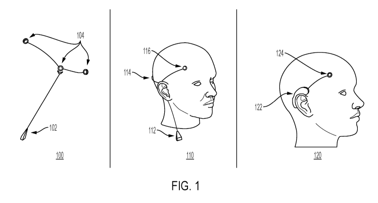
FIG. 1 shows different aspects 100, 110, and 120 of a device wearable by a
person for treating a symptom of a neurological disorder, in accordance with
some
embodiments of the technology described herein. The device may be a non-
invasive
seizure prediction and/or detection device. In some embodiments, in aspect
100, the
device may include a local processing device 102 and one or more electrodes
104. The
local processing device 102 may include a wristwatch, an arm band, a necklace,
a
wireless earbud, or another suitable device. The local processing device 102
may
include a radio and/or a physical connector for transmitting data to a cloud
server, a
mobile phone, or another suitable device. The local processing device 102 may
receive,
from a sensor, a signal detected from the brain and transmit an instruction to
a
transducer to apply to the brain an acoustic signal. The electrodes 104 may
include one
or more sensors configured to detect a signal from the brain of the person,
e.g., an EEG
signal, and/or one or more transducers configured to apply to the brain an
acoustic
signal, e.g., an ultrasound signal. The acoustic signal may have a low power
density
and be substantially non-destructive with respect to tissue when applied to
the brain. In
some embodiments, one electrode may include either a sensor or a transducer.
In some
embodiments, one electrode may include both a sensor and a transducer. In some
embodiments, one, 10, 20, or another suitable number of electrodes may be
available.
The electrodes may be removably attached to the device.
In some embodiments, in aspect 110, the device may include a local processing
device 112, a sensor 114, and a transducer 116. The device may be disposed on
the
head of the person in a non-invasive manner, such as placed on the scalp of
the person
or in another suitable manner. The local processing device 112 may include a
wristwatch, an arm band, a necklace, a wireless earbud, or another suitable
device. The
local processing device 112 may include a radio and/or a physical connector
for
transmitting data to a cloud server, a mobile phone, or another suitable
device. The
local processing device 112 may receive, from the sensor 114, a signal
detected from
the brain and transmit an instruction to the transducer 116 to apply to the
brain an
acoustic signal. The sensor 114 may be configured to detect a signal from the
brain of
the person, e.g., an EEG signal. The transducer 116 may be configured to apply
to the
brain an acoustic signal, e.g., an ultrasound signal. The acoustic signal may
have a low
21
CA 03122273 2021-06-04
WO 2020/123948
PCT/US2019/066242
power density and be substantially non-destructive with respect to tissue when
applied
to the brain. In some embodiments, one electrode may include either a sensor
or a
transducer. In some embodiments, one electrode may include both a sensor and a
transducer. In some embodiments, one, 10, 20, or another suitable number of
electrodes
may be available. The electrodes may be removably attached to the device.
In some embodiments, in aspect 120, the device may include a local processing
device 122 and an electrode 124. The device may be disposed on the head of the
person
in a non-invasive manner, such as placed over the ear of the person or in
another suitable
manner. The local processing device 122 may include a wristwatch, an arm band,
a
necklace, a wireless earbud, or another suitable device. The local processing
device
122 may include a radio and/or a physical connector for transmitting data to a
cloud
server, a mobile phone, or another suitable device. The local processing
device 122
may receive, from the electrode 124, a signal detected from the brain and/or
transmit
an instruction to the electrode 124 to apply to the brain an acoustic signal.
The electrode
124 may include a sensor configured to detect a signal from the brain of the
person,
e.g., an EEG signal, and/or a transducer configured to apply to the brain an
acoustic
signal, e.g., an ultrasound signal. The acoustic signal may have a low power
density
and be substantially non-destructive with respect to tissue when applied to
the brain. In
some embodiments, the electrode 124 may include either a sensor or a
transducer. In
some embodiments, the electrode 124 may include both a sensor and a
transducer. In
some embodiments, one, 10, 20, or another suitable number of electrodes may be
available. The electrodes may be removably attached to the device.
In some embodiments, the device may include one or more sensors for detecting
sound, motion, optical signals, heart rate, and other suitable sensing
modalities. For
example, the sensor may detect an electrical signal, a mechanical signal, an
optical
signal, an infrared signal, or another suitable type of signal. In some
embodiments, the
device may include a wireless earbud, a sensor embedded in the wireless
earbud, and a
transducer. The sensor may detect a signal, e.g., an EEG signal, from the
brain of the
person while the wireless earbud is present in the person's ear. The wireless
earbud
may have an associated case or enclosure that includes a local processing
device for
receiving and processing the signal from the sensor and/or transmitting an
instruction
to the transducer to apply to the brain an acoustic signal.
22
CA 03122273 2021-06-04
WO 2020/123948
PCT/US2019/066242
In some embodiments, the device may include a sensor for detecting a
mechanical signal, such as a signal with a frequency in the audible range. For
example,
the sensor may be used to detect an audible signal from the brain indicating a
seizure.
The sensor may be an acoustic receiver disposed on the scalp of the person to
detect an
audible signal from the brain indicating a seizure. In another example, the
sensor may
be an accelerometer disposed on the scalp of the person to detect an audible
signal from
the brain indicating a seizure. In this manner, the device may be used to
"hear" the
seizure around the time it occurs.
FIGs. 2A-2B show illustrative examples of a device wearable by a person for
treating a symptom of a neurological disorder and mobile device(s) executing
an
application in communication with the device, in accordance with some
embodiments
of the technology described herein. FIG. 2A shows an illustrative example of a
device
200 wearable by a person for treating a symptom of a neurological disorder and
a
mobile device 210 executing an application in communication with the device
200. In
some embodiments, the device 200 may be capable of predicting seizures,
detecting
seizures and alerting users or caretakers, tracking and managing the
condition, and/or
suppressing symptoms of neurological disorders, such as seizures. The device
200 may
connect to the mobile device 210, such as a mobile phone, watch, or another
suitable
device via BLUETOOTH, WIFI, or another suitable connection. The device 200 may
monitor neuronal activity with one or more sensors 202 and share data with a
user, a
caretaker, or another suitable entity using processor 204. The device 200 may
learn
about individual patient patterns. The device 200 may access data from prior
signals
detected from the brain from an electronic health record of the person wearing
the
device 200.
FIG. 2B shows illustrative examples of mobile devices 250 and 252 executing
an application in communication with a device wearable by a person for
treating a
symptom of a neurological disorder, e.g., device 200. For example, the mobile
device
250 or 252 may display real-time seizure risk for the person suffering from
the
neurological disorder. In the event of a seizure, the mobile device 250 or 252
may alert
the person, a caregiver, or another suitable entity. For example, the mobile
device 250
or 252 may inform a caretaker that a seizure is predicted in the next 30
minutes, next
hour, or another suitable time period. In another example, the mobile device
250 or
252 may send alerts to the caretaker when a seizure does occur and/or record
seizure
23
CA 03122273 2021-06-04
WO 2020/123948
PCT/US2019/066242
activity, such as signals from the brain, for the caretaker to refine
treatment of the
person's neurological disorder. In some embodiments, the wearable device 200
and/or
the mobile device 250 or 252 may analyze a signal, such as an EEG signal,
detected
from the brain to determine whether the brain is exhibiting a symptom of a
neurological
disorder. The wearable device 200 may apply to the brain an acoustic signal,
such as
an ultrasound signal, in response to determining that the brain is exhibiting
the symptom
of the neurological disorder.
In some embodiments, the wearable device 200, the mobile device 250 or 252,
and/or another suitable computing device may provide one or more signals,
e.g., an
EEG signal or another suitable signal, detected from the brain to a deep
learning
network to determine whether the brain is exhibiting a symptom of a
neurological
disorder, e.g., a seizure or another suitable symptom. The deep learning
network may
be trained on data gathered from a population of patients and/or the person
wearing the
wearable device 200. The mobile device 250 or 252 may generate an interface to
warn
the person and/or a caretaker when the person is likely to have a seizure
and/or when
the person will be seizure-free. In some embodiments, the wearable device 200
and/or
the mobile device 250 or 252 may allow for two-way communication to and from
the
person suffering from the neurological disorder. For example, the person may
inform
the wearable device 200 via text, speech, or another suitable input mode that
"I just had
a beer, and I'm worried I may be more likely to have a seizure." The wearable
device
200 may respond using a suitable output mode that "Okay, the device will be on
high
alert." The deep learning network may use this information to assist in future
predictions for the person. For example, the deep learning network may add
this
information to data used for updating/training the deep learning network. In
another
example, the deep learning network may use this information as input to help
predict
the next symptom for the person. Additionally or alternatively, the wearable
device
200 may assist the person and/or the caretaker in tracking sleep and/or diet
patterns of
the person suffering from the neurological disorder and provide this
information when
requested. The deep learning network may add this information to data used for
updating/training the deep learning network and/or use this information as
input to help
predict the next symptom for the person. Further information regarding the
deep
learning network is provided with respect to FIGs. 11B and 11C.
24
CA 03122273 2021-06-04
WO 2020/123948
PCT/US2019/066242
FIG. 3A shows an illustrative example 300 of a mobile device and/or a cloud
server in communication with a device wearable by a person for treating a
symptom of
a neurological disorder, in accordance with some embodiments of the technology
described herein. In this example, the wearable device 302 may monitor brain
activity
with one or more sensors and send the data to the person's mobile device 304,
e.g., a
mobile phone, a wristwatch, or another suitable mobile device. The mobile
device 304
may analyze the data and/or send the data to a server 306, e.g., a cloud
server. The
server 306 may execute one or more machine learning algorithms to analyze the
data.
For example, the server 306 may use a deep learning network that takes the
data or a
portion of the data as input and generates output with information about one
or more
predicted symptoms, e.g., a predicted strength of a seizure. The analyzed data
may be
displayed on the mobile device 304 and/or an application on a computing device
308.
For example, the mobile device 304 and/or computing device 308 may display
real-
time seizure risk for the person suffering from the neurological disorder. In
the event
of a seizure, the mobile device 304 and/or computing device 308 may alert the
person,
a caregiver, or another suitable entity. For example, the mobile device 304
and/or
computing device 308 may inform a caretaker that a seizure is predicted in the
next 30
minutes, next hour, or another suitable time period. In another example, the
mobile
device 304 and/or computing device 308 may send alerts to the caretaker when a
seizure
does occur and/or record seizure activity, such as signals from the brain, for
the
caretaker to refine treatment of the person's neurological disorder.
In some embodiments, one or more alerts may be generated by a machine
learning algorithm trained to detect and/or predict seizures. For example, the
machine
learning algorithm may include a deep learning network, e.g., as described
with respect
to FIGs. 11B and 11C. When the algorithm detects that a seizure is present, or
predicts
that a seizure is likely to develop in the near future (e.g., within an hour),
an alert may
be sent to a mobile application. The interface of the mobile application may
include
bi-directional communication, e.g., in addition to the mobile application
sending
notifications to the patient, the patient may have the ability to enter
information into the
mobile application to improve the performance of the algorithm. For example,
if the
machine learning algorithm is not certain within a confidence threshold that
the patient
is having a seizure, it may send a question to the patient through the mobile
application,
CA 03122273 2021-06-04
WO 2020/123948
PCT/US2019/066242
asking the patient whether or not he/she recently had a seizure. If the
patient answers
no, the algorithm may take this into account and train or re-train
accordingly.
FIG. 3B shows a block diagram 350 of a mobile device and/or a cloud server in
communication with a device wearable by a person for treating a symptom of a
neurological disorder, in accordance with some embodiments of the technology
described herein. Device 360 may include a wristwatch, an arm band, a
necklace, a
wireless earbud, or another suitable device. The device 360 may include one or
more
sensors (block 362) to acquire signals from the brain (e.g., from EEG sensors,
accelerometers, electrocardiogram (EKG) sensors, and/or other suitable
sensors). The
device 360 may include an analog front-end (block 364) for conditioning,
amplifying,
and/or digitizing the signals acquired by the sensors (block 362). The device
360 may
include a digital back-end (block 366) for buffering, pre-processing, and/or
packetizing
the output signals from the analog front-end (block 364). The device 360 may
include
data transmission circuitry (block 368) for transmitting the data from the
digital back-
end (block 366) to a mobile application 370, e.g., via BLUETOOTH. Additionally
or
alternatively, the data transmission circuitry (block 368) may send debugging
information to a computer, e.g., via USB, and/or send backup information to
local
storage, e.g., a microSD card.
The mobile application 370 may execute on a mobile phone or another suitable
device. The mobile application 370 may receive data from the device 370 (block
372)
and send the data to a cloud server 380 (block 374). The cloud server 380 may
receive
data from the mobile application 370 (block 382) and store the data in a
database (block
383). The cloud server 380 may extract detection features (block 384), run a
detection
algorithm (block 386), and send results back to the mobile application 370
(block 388).
Further details regarding the detection algorithm are described later in this
disclosure,
including with respect to FIGs. 11B and 11C. The mobile application 370 may
receive
the results from the cloud server 380 (block 376) and display the results to
the user
(block 378).
In some embodiments, the device 360 may transmit the data directly to the
cloud
server 380, e.g., via the Internet. The cloud server 380 may send the results
to the
mobile application 370 for display to the user. In some embodiments, the
device 360
may transmit the data directly to the cloud server 380, e.g., via the
Internet. The cloud
server 380 may send the results back to the device 360 for display to the
user. For
26
CA 03122273 2021-06-04
WO 2020/123948
PCT/US2019/066242
example, the device 360 may be a wristwatch with a screen for displaying the
results.
In some embodiments, the device 360 may transmit the data to the mobile
application
370, and the mobile application 370 may extract detection features, run a
detection
algorithm, and/or display the results to the user on the mobile application
370 and/or
the device 360. Other suitable variations of interactions between the device
360, the
mobile application 370, and/or the cloud server 380 may be possible and are
within the
scope of this disclosure.
FIG. 4 shows a block diagram for a wearable device 400 including stimulation
and monitoring components, in accordance with some embodiments of the
technology
described herein. The device 400 is wearable by (or attached to or implanted
within) a
person and includes a monitoring component 402, a stimulation component 404,
and a
processor 406. The monitoring component 402 may include a sensor that is
configured
to detect a signal, e.g., an electrical signal, a mechanical signal, an
optical signal, an
infrared signal, or another suitable type of signal, from the brain of the
person. For
example, the sensor may be an electroencephalogram (EEG) sensor, and the
signal may
be an electrical signal, such as an EEG signal. The stimulation component 404
may
include a transducer configured to apply to the brain an acoustic signal. For
example,
the transducer may be an ultrasound transducer, and the acoustic signal may be
an
ultrasound signal. In some embodiments, the ultrasound signal may have a low
power
density and be substantially non-destructive with respect to tissue when
applied to the
brain. In some embodiments, the sensor and the transducer may be disposed on
the
head of the person in a non-invasive manner.
The processor 406 may be in communication with the monitoring component
402 and the stimulation component 404. The processor 406 may be programmed to
receive, from the monitoring component 402, the signal detected from the brain
and
transmit an instruction to the stimulation component 404 to apply to the brain
the
acoustic signal. In some embodiments, the processor 406 may be programmed to
transmit the instruction to the stimulation component 404 to apply to the
brain the
acoustic signal at one or more random intervals. In some embodiments, the
stimulation
component 404 may include two or more transducers, and the processor 406 may
be
programmed to select one of the transducers to transmit the instruction to
apply to the
brain the acoustic signal at one or more random intervals.
27
CA 03122273 2021-06-04
WO 2020/123948
PCT/US2019/066242
In some embodiments, the processor 406 may be programmed to analyze the
signal from the monitoring component 402 to determine whether the brain is
exhibiting
a symptom of a neurological disorder. The processor 406 may transmit the
instruction
to the stimulation component 404 to apply to the brain the acoustic signal in
response
to determining that the brain is exhibiting the symptom of the neurological
disorder.
The acoustic signal may suppress the symptom of the neurological disorder. For
example, the symptom may be a seizure, and the neurological disorder may be
one or
more of stroke, Parkinson's disease, migraine, tremors, frontotemporal
dementia,
traumatic brain injury, depression, anxiety, Alzheimer's disease, dementia,
multiple
sclerosis, schizophrenia, brain damage, neurodegeneration, central nervous
system
(CNS) disease, encephalopathy, Huntington' s disease, autism, attention
deficit
hyperactivity disorder (ADHD), amyotrophic lateral sclerosis (ALS), and
concussion.
In some embodiments, the software to program the ultrasound transducers may
send real-time sensor readings (e.g., from EEG sensors, accelerometers, EKG
sensors,
and/or other suitable sensors) to a processor running machine learning
algorithms
continuously, e.g., a deep learning network as described with respect to FIGs.
11B and
11C. For example, this processor may be local, on the device itself, or in the
cloud.
These machine learning algorithms executing on the processor may perform three
tasks:
1) detect when a seizure is present, 2) predict when a seizure is likely to
occur within
the near future (e.g., within one hour), and 3) output a location to aim the
stimulating
ultrasound beam. Immediately after the processor detects that a seizure has
begun, the
stimulating ultrasound beam may be turned on and aimed at the location
determined by
the output of the algorithm(s). For patients with seizures that always have
the same
characteristics/focus, it is likely that once a good beam location is found,
it may not
change. Another example for how the beam may be activated is when the
processor
predicts that a seizure is likely to occur in the near future, the beam may be
turned on
at a relatively low intensity (e.g., relative to the intensity used when a
seizure is
detected). In some embodiments, the target for the stimulating ultrasound beam
may
not be the seizure focus itself. For example, the target may be a seizure
"choke point,"
i.e., a location outside of the seizure focus that when stimulated can shut
down seizure
activity.
FIG. 5 shows a block diagram for a wearable device 500 for substantially non-
destructive acoustic stimulation, in accordance with some embodiments of the
28
CA 03122273 2021-06-04
WO 2020/123948
PCT/US2019/066242
technology described herein. The device 500 is wearable by a person and
includes a
monitoring component 502 and a stimulation component 504. The monitoring
component 502 and/or the stimulation component 504 may be disposed on the head
of
the person in a non-invasive manner.
The monitoring component 502 may include a sensor that is configured to detect
a signal, e.g., an electrical signal, a mechanical signal, an optical signal,
an infrared
signal, or another suitable type of signal, from the brain of the person. For
example,
the sensor may be an electroencephalogram (EEG) sensor, and the signal may be
an
EEG signal. The stimulation component 504 may include an ultrasound transducer
configured to apply to the brain an ultrasound signal that has a low power
density, e.g.,
between 1 and 100 watts/cm2, and is substantially non-destructive with respect
to tissue
when applied to the brain. For example, the ultrasound signal may have a
frequency
between 100 kHz and 1 MHz, a spatial resolution between 0.001 cm3 and 0.1 cm3,
and/or the low power density between 1 and 100 watts/cm2 as measured by
spatial-peak
pulse-average intensity. The ultrasound signal may suppress the symptom of the
neurological disorder. For example, the symptom may be a seizure, and the
neurological disorder may be epilepsy or another suitable neurological
disorder.
FIG. 6 shows a block diagram for a wearable device 600 for acoustic
stimulation, e.g., randomized acoustic stimulation, in accordance with some
embodiments of the technology described herein. The device 600 is wearable by
a
person and includes a stimulation component 604 and a processor 606. The
stimulation
component 604 may include a transducer that is configured to apply to the
brain of the
person acoustic signals. For example, the transducer may be an ultrasound
transducer,
and the acoustic signal may be an ultrasound signal. In some embodiments, the
ultrasound signal may have a low power density and be substantially non-
destructive
with respect to tissue when applied to the brain. In some embodiments, the
transducer
may be disposed on the head of the person in a non-invasive manner.
In some embodiments, the processor 606 may transmit an instruction to the
stimulation component 604 to activate the brain tissue at random intervals,
e.g.,
sporadically throughout the day and/or night, thereby preventing the brain
from settling
into a seizure state. For example, for patients with generalized epilepsy, the
device 600
may stimulate the thalamus or another suitable region of the brain at random
times
throughout the day and/or night, e.g., around every 10 minutes. In some
embodiments,
29
CA 03122273 2021-06-04
WO 2020/123948
PCT/US2019/066242
the stimulation component 604 may include another transducer. The device 600
and/or
the processor 606 may select one of the transducers to apply to the brain the
acoustic
signal at one or more random intervals.
FIG. 7 shows a block diagram for a wearable device 700 for treating a
neurological disorder using ultrasound stimulation, in accordance with some
embodiments of the technology described herein. The device 700 is wearable by
(or
attached to or implanted within) a person and can be used to treat epileptic
seizures.
The device 700 includes a sensor 702, a transducer 704, and a processor 706.
The
sensor 702 may be configured to detect an EEG signal from the brain of the
person.
The transducer 704 may be configured to apply to the brain a low power,
substantially
non-destructive ultrasound signal. The ultrasound signal may suppress one or
more
epileptic seizures. For example, the ultrasound signal may have a frequency
between
100 kHz and 1 MHz, a spatial resolution between 0.001 cm3 and 0.1 cm3, and/or
a
power density between 1 and 100 watts/cm- as measured by spatial-peak pulse-
average
intensity. In some embodiments, the sensor and the transducer may be disposed
on the
head of the person in a non-invasive manner.
The processor 706 may be in communication with the sensor 702 and the
transducer 704. The processor 706 may be programmed to receive, from the
sensor
702, the EEG signal detected from the brain and transmit an instruction to the
transducer
704 to apply to the brain the ultrasound signal. In some embodiments, the
processor
706 may be programmed to analyze the EEG signal to determine whether the brain
is
exhibiting an epileptic seizure and, in response to determining that the brain
is
exhibiting the epileptic seizure, transmit the instruction to the transducer
704 to apply
to the brain the ultrasound signal.
In some embodiments, the processor 706 may be programmed to transmit an
instruction to the transducer 704 to apply to the brain the ultrasound signal
at one or
more random intervals. In some embodiments, the transducer 704 may include two
or
more transducers, and the processor 706 may be programmed to select one of the
transducers to transmit an instruction to apply to the brain the ultrasound
signal at one
or more random intervals.
Closed-Loop System using Machine Leamin to Steer Focus of Ultrasound Beam
within Human Brain
CA 03122273 2021-06-04
WO 2020/123948
PCT/US2019/066242
Conventional brain-machine interfaces are limited in that the brain regions
that
receive stimulation may not be changed in real time. This may be problematic
because
it is often difficult to locate an appropriate brain region to stimulate in
order to treat
symptoms of neurological disorders. For example, in epilepsy, it may not be
clear
which region within the brain should be stimulated to suppress or stop a
seizure. The
appropriate brain region may be the seizure focus (which can be difficult to
localize), a
region that may serve to suppress the seizure, or another suitable brain
region.
Conventional solutions, such as implantable electronic responsive neural
stiinulators
and deep brain stimulators, can only be positioned once by doctors taking
their best
guess or choosing some pre-determined region of the brain. Therefore, brain
regions
that can receive stimulation cannot be changed in real time in conventional
systems.
The inventors have appreciated that treatment for neurological disorders may
be more effective when the brain region of the stimulation may be changed in
real time,
and in particular, when the brain region may be changed remotely. Because the
brain
region may be changed in real time and/or remotely, tens (or more) of
locations per
second may be tried, thereby closing in on the appropriate brain region for
stimulation
quickly with respect to the duration of an average seizure. Such a treatment
may be
achievable using ultrasound to stimulate the brain. In some embodiments, the
patient
may wear an array of ultriNound transducers (e.g., such an array is placed on
the scalp
of the person), and an ultrasound beam may be steered using beamforming
methods
such as phased arrays. In some embodiments, with wedge transducers, fewer
number
of transducers may be used. In some embodiments, with wedge transducers, the
device
may be more energy efficient due to lower power requirements of the wedge
transducers. U.S. Patent Application Publication No. 2018/0280735 provides
further
information on exemplary embodiments of the wedge transducers, the entirety of
which
incorporated by reference herein. The target of the beam may be changed by
programming the array. If stimulation in a certain brain region is not
working, the beam
may be moved to another region of the brain to try again, at no harm to the
patient.
In some embodiments, a machine learning algorithm that senses the brain state
may be connected to the beam steering algorithm to make a closed-loop system,
e.g.,
including a deep learning network. The machine learning algorithm that senses
the
brain state may take as input recordings from EEG sensors, EKG sensors,
accelerometers, and/or other suitable sensors. Various filters may be applied
to these
31
CA 03122273 2021-06-04
WO 2020/123948
PCT/US2019/066242
combined inputs, and the outputs of these filters may be combined in a
generally
nonlinear fashion, to extract a useful representation of the data. Then, a
classifier may
be trained on this high-level representation. This may be accomplished using
deep
learning and/or by pre-specifying the filters and training a classifier, such
as a Support
Vector Machine (SVM). In some embodiments, the machine learning algorithm may
include training a recurrent neural network (RNN), such as a long short-term
memory
(LSTM) unit based RNN, to map the high-dimensional input data into a smoothly-
varying trajectory through a latent space representative of a higher-level
brain state.
These machine learning algorithms executing on the processor may perform three
tasks:
1) detect when a symptom of a neurological disorder is present, e.g., a
seizure, 2) predict
when a symptom is likely to occur within the near future (e.g., within one
hour), and 3)
output a location to aim the stimulating acoustic signal, e.g., an ultrasound
beam. Any
or all of these tasks may be performed using a deep learning network or
another suitable
network. More details regarding this technique are described later in this
disclosure,
including with respect to FIGs. 11B and 11C.
Taking the example of epilepsy, the goal may be to suppress or stop a seizure
that has already started. In this example, the closed-loop system may work as
follows.
First, the system may execute a measurement algorithm that measures the
"strength" of
seizure activity, with the beam positioned in some preset initial location
(for example,
the hippocampus for patients with temporal lobe epilepsy). The beam location
may
then be slightly changed and the resulting change in seizure strength may be
measured
using the measurement algorithm. if the seizure activity has reduced, the
system may
continue moving the beam in this direction. If the seizure activity has
increased, the
system may move the beam in the opposite or a different direction. Because the
beam
location may be programmed electronically, tens of beam locations per second
may be
tried, thereby closing in on the appropriate stimulation location quickly with
respect to
the duration of an average seizure.
In some embodiments, some brain regions may be inappropriate for stimulation.
For example, stimulating parts of the brain stern may lead to irreversible
damage or
discomfort. In this case, the closed-loop system may follow a "constrained"
gradient
descent solution where the appropriate stimulation location is taken from a
set of
feasible points. This may ensure that the off-lirnit brain regions are never
stimulated.
32
CA 03122273 2021-06-04
WO 2020/123948
PCT/US2019/066242
FIG. 8 shows a block diagram for a device 800 to steer acoustic stimulation,
in
accordance with some embodiments of the technology described herein. The
device
800, e.g., a wearable device, may be part of a closed-loop system that uses
machine
learning to steer focus of an ultrasound beam within the brain. The device 800
may
include a monitoring component 802, e.g., a sensor, that is configured to
detect a signal,
e.g., an electrical signal, a mechanical signal, an optical signal, an
infrared signal, or
another suitable type of signal, from the brain of the person. For example,
the sensor
may be an EEG sensor, and the signal may be an electrical signal, such as an
EEG
signal. The device 800 may include a stimulation component 804, e.g., a set of
transducers, each configured to apply to the brain an acoustic signal. For
example, one
or more of the transducers may be an ultrasound transducer, and the acoustic
signal may
be an ultrasound signal. The sensor and/or the set of transducers may be
disposed on
the head of the person in a non-invasive manner. In some embodiments, the
device 800
may include a processor 806 in communication with the sensor and the set of
transducers. The processor 806 may select one of the transducers using a
statistical
model trained on data from prior signals detected from the brain. For example,
data
from prior signals detected from the brain may be accessed from an electronic
health
record of the person.
FIG. 9 shows a flow diagram 900 for a device to steer acoustic stimulation, in
accordance with some embodiments of the technology described herein.
At 902, the processor, e.g., processor 806, may receive, from the sensor, data
from a first signal detected from the brain.
At 904, the processor may access a trained statistical model. The statistical
model may be trained using data from prior signals detected from the brain.
For
example, the statistical model may include a deep learning network trained
using data
from the prior signals detected from the brain.
At 906, the processor may provide data from the first signal detected from the
brain as input to the trained statistical model, e.g., a deep learning
network, to obtain
an output indicating a first predicted strength of a symptom of a neurological
disorder,
e.g., an epileptic seizure.
At 908, based on the first predicted strength of the symptom, the processor
may
select one of the transducers in a first direction to transmit a first
instruction to apply a
first acoustic signal. For example, the first acoustic signal may be an
ultrasound signal
33
CA 03122273 2021-06-04
WO 2020/123948
PCT/US2019/066242
that has a low power density, e.g., between 1 and 100 watts/cm2, and is
substantially
non-destructive with respect to tissue when applied to the brain. The acoustic
signal
may suppress the symptom of the neurological disorder.
At 910, the processor may transmit the instruction to the selected transducer
to
apply the first acoustic signal to the brain.
In some embodiments, the processor may be programmed to provide data from
a second signal detected from the brain as input to the trained statistical
model to obtain
an output indicating a second predicted strength of the symptom of the
neurological
disorder. If it is determined that the second predicted strength is less than
the first
predicted strength, the processor may select one of the transducers in the
first direction
to transmit a second instruction to apply a second acoustic signal. If it is
determined
that the second predicted strength is greater than the first predicted
strength, the
processor may select one of the transducers in a direction opposite to or
different from
the first direction to transmit the second instruction to apply the second
acoustic signal.
Novel Detection Algorithms
Conventional approaches consider seizure detection to be a classification
problem. For example, a window of EEG data (e.g., 5 seconds long) may be fed
into a
classifier which outputs a binary label representing whether or not the input
is from a
seizure. Running the algorithm in real time may entail running the algorithm
on
consecutive windows of EEG data. However, the inventors have discovered that
there
is nothing in such an algorithm structure, or in the training of the
algorithm, to
accommodate that the brain does not quickly switch back and forth between
seizure and
non-seizure. If the current window is a seizure, there is a high probability
that the next
window will be a seizure too. This reasoning will only fail for the very end
of the
seizure. Similarly, if the current window is not a seizure, there is a high
probability that
the next window will also not be a seizure. This reasoning will only fail for
the very
beginning of the seizure. The inventors have appreciated that it would be
preferable to
reflect the "smoothness" of seizure state in the structure of the algorithm or
in the
training by penalizing network outputs that oscillate on short time scales.
The inventors
have accomplished this by, for example, adding a regularization term to the
loss
function that is proportional to the total variation of the outputs, or the
L1/L2 norm of
the derivative (computed via finite difference) of the outputs, or the L1/L2
norm of the
34
CA 03122273 2021-06-04
WO 2020/123948
PCT/US2019/066242
second derivative of the outputs. In some embodiments, RNNs with LSTM units
may
automatically give smooth output. In some embodiments, a way to achieve
smoothness
of the detection outputs may be to train a conventional, non-smooth detection
algorithm, and feed its results into a causal low-pass filter, and using this
low-pass
filtered output as the final result. This may ensure that the final result is
smooth. For
example, the non-smooth detection algorithm may use one or both of the
following
equations to generate the final result:
n
L(W) = E Ily[i] - 9w[i]2 + Abw[i]lkTV
i=1 (1)
n
L(W) = E Ily[i] - 9w[i]112 + A[i] - - 11 I
(2)
In equations (1) and (2), y[i] is the ground-truth label of seizure, or no
seizure,
for sample i, ;Ai] is the output of the algorithm for sample i. L(w) is the
machine
learning loss function evaluated at the model parameterized by w (meant to
represent
the weights in a network). The first term in L(w) may measure how accurately
the
algorithm classifies seizures. The second term in L(w) (multiplied by A) is a
regularization term that may encourage the algorithm to learn solutions that
change
smoothly over time. Equations (1) and (2) are two examples for regularization
as
shown. Equation (1) is the total variation (TV) norm, and equation (2) is the
absolute
value of the first derivative. Both equations may try to enforce smoothness.
In equation
(1), the TV norm may be small for a smooth output and large for an output that
is not
smooth. In equation (2), the absolute value of the first derivative is
penalized to try to
enforce smoothness. In certain cases, equation (1) may work better than
equation (2),
or vice versa, the results of which may be determined empirically by training
a
conventional, non-smooth detection algorithm using equation (1) and comparing
the
final result to a similar algorithm trained using equation (2).
Conventionally, EEG data is annotated in a binary fashion, so that one moment
is classified as not a seizure and the next is classified as a seizure. The
exact seizure
start and end times are relatively arbitrary because there may not be an
objective way
to locate the beginning and end of a seizure. However, using conventional
algorithms,
the detection algorithm may be penalized for not perfectly agreeing with the
annotation.
The inventors have appreciated that it may be better to "smoothly" annotate
the data,
e.g., using smooth window labels that rise from 0 to 1 and fall smoothly from
1 back to
CA 03122273 2021-06-04
WO 2020/123948
PCT/US2019/066242
0, with 0 representing a non-seizure and 1 representing a seizure. This
annotation
scheme may better reflect that seizures evolve over time and that there may be
ambiguity involved in the precise demarcation. Accordingly, the inventors have
applied this annotation scheme to recast seizure detection from a detection
problem to
a regression machine learning problem.
FIG. 10 shows a block diagram for a device using a statistical model trained
on
annotated signal data, in accordance with some embodiments of the technology
described herein. The statistical model may include a deep learning network or
another
suitable model. The device 1000, e.g., a wearable device, may include a
monitoring
component 1002, e.g., a sensor, that is configured to detect a signal, e.g.,
an electrical
signal, a mechanical signal, an optical signal, an infrared signal, or another
suitable type
of signal, from the brain of the person. For example, the sensor may be an EEG
sensor,
and the signal may be an EEG signal. The device 1000 may include a stimulation
component 1004, e.g., a set of transducers, each configured to apply to the
brain an
acoustic signal. For example, one or more of the transducers may be an
ultrasound
transducer, and the acoustic signal may be an ultrasound signal. The sensor
and/or the
set of transducers may be disposed on the head of the person in a non-invasive
manner.
In some embodiments, the device 1000 may include a processor 1006 in
communication with the sensor and the set of transducers. The processor 1006
may
select one of the transducers using a statistical model trained on signal data
annotated
with one or more values relating to identifying a health condition, e.g.,
respective values
relating to increasing strength of a symptom of a neurological disorder. For
example,
the signal data may include data from prior signals detected from the brain
and may be
accessed from an electronic health record of the person. In some embodiments,
the
statistical model may be trained on data from prior signals detected from the
brain
annotated with the respective values, e.g., between 0 and 1, relating to
increasing
strength of the symptom of the neurological disorder. in some embodiments, the
statistical model may include a loss function having a regularization term
that is
proportional to a variation of outputs of the statistical model, an L 1/L2
norm of a
derivative of the outputs, or an L 1/L2 norm of a second derivative of the
outputs.
FIG. 11A shows a flow diagram 1100 for a device using a statistical model
trained on annotated signal data, in accordance with some embodiments of the
technology described herein.
36
CA 03122273 2021-06-04
WO 2020/123948
PCT/US2019/066242
At 1102, the processor, e.g., processor 1006, may receive, from the sensor,
data
from a first signal detected from the brain.
At 1104, the processor may access a trained statistical model, wherein the
statistical model was trained using data from prior signals detected from the
brain
annotated with one or more values relating to identifying a health condition,
e.g.,
respective values (e.g., between 0 and 1) relating to increasing strength of a
symptom
of a neurological disorder.
At 1106, the processor may provide data from the first signal detected from
the
brain as input to the trained statistical model to obtain an output indicating
a first
predicted strength of the symptom of the neurological disorder, e.g., an
epileptic
seizure.
At 1108, based on the first predicted strength of the symptom, the processor
may select one of the plurality of transducers in a first direction to
transmit a first
instruction to apply a first acoustic signal.
At 1110, the processor may transmit the instruction to the selected transducer
to
apply the first acoustic signal to the brain. For example, the first acoustic
signal may
be an ultrasound signal that has a low power density, e.g., between 1 and 100
watts/cm2,
and is substantially non-destructive with respect to tissue when applied to
the brain.
The acoustic signal may suppress the symptom of the neurological disorder.
In some embodiments, the processor may be programmed to provide data from
a second signal detected from the brain as input to the trained statistical
model to obtain
an output indicating a second predicted strength of the symptom of the
neurological
disorder. If it is determined that the second predicted strength is less than
the first
predicted strength, the processor may select one of the transducers in the
first direction
to transmit a second instruction to apply a second acoustic signal. If it is
determined
that the second predicted strength is greater than the first predicted
strength, the
processor may select one of the transducers in a direction opposite to or
different from
the first direction to transmit the second instruction to apply the second
acoustic signal.
In some embodiments, the inventors have developed a deep learning network to
detect one or more other symptoms of a neurological disorder. For example, the
deep
learning network may be used to predict seizures. The deep learning network
includes
a Deep Convolutional Neural Network (DCNN), which embeds or encodes the data
onto a n-dimensional representation space (e.g., 16-dimensional) and a
Recurrent
37
CA 03122273 2021-06-04
WO 2020/123948
PCT/US2019/066242
Neural Network (RNN), which computes detection scores by observing changes in
the
representation space through time. However, the deep learning network is not
so
limited and may include alternative or additional architectural components
suitable for
predicting one or more symptoms of a neurological disorder.
In some embodiments, the features that are provided as input to the deep
learning network may be received and/or transformed in the time domain or the
frequency domain. In some embodiments, a network trained using frequency
domain-
based features may output more accurate predictions compared to another
network
trained using time domain-based features. For example, a network trained using
frequency domain-based features may output more accurate predictions because
the
wave shape induced in EEG signal data captured during a seizure may have
temporally
limited exposure. Accordingly, a discrete wavelet transform (DWT), e.g., with
the
Daubechies 4-tab (db-4) mother wavelet or another suitable wavelet, may be
used to
transform the EEG signal data into the frequency domain. Other suitable
wavelet
transforms may be used additionally or alternatively in order to transform the
EEG
signal data into a form suitable for input to the deep learning network. In
some
embodiments, one-second windows of EEG signal data at each channel may be
chosen
and the DWT may be applied up to 5 levels, or another suitable number of
levels. In
this case, each batch input to the deep learning network may be a tensor with
dimensions
equal to (batch size x sampling frequency x number of EEG channels x DWT
levels +
1). This tensor may be provided to the DCNN encoder of the deep learning
network.
In some embodiments, signal statistics may be different for different people
and
may change over time even for a particular person. Hence, the network may be
highly
susceptible to overfitting especially when the provided training data is not
large enough.
This information may be utilized in developing the training framework for the
network
such that the DCNN encoder can embed the signal onto a space in which at least
temporal drifts convey information about seizure. During the training, one or
more
objective functions may be used to fit the DCNN encoder, including a Siamese
loss and
a classification loss, which are further described below.
1. Siamese loss: In one-shot or few-shot learning frameworks, i.e.,
frameworks with small training data sets, a Siamese loss based network may be
designed to indicate a pair of input instances are from the same category or
not. The
38
CA 03122273 2021-06-04
WO 2020/123948
PCT/US2019/066242
setup in the network may be aimed to detect if two temporally close samples
are both.
from the same category or not in the same patient.
2. Classification loss: Binary-cross entropy is a widely used
objective
function for supervised learning. This objective function may be used to
decrease the
distance among embed.dings from the same category while increasing the
distance
between classes as much as possible, regardless of piecewi.se behavior and
subjectivity
of EEG signal statistics. The paired data segments mat help to increase sample
comparisons quadratically and hence mitigate the overfitting caused by lack of
data.
In some embodiments, each time a batch of training data is formed, the onset
of
one-second windows may be selected randomly to help with data augmentation,
thereby
increasing the size of the training data.
In some embodiments, the DCNN encoder may include a 13-layer 2-D
convolutional neural network with fractional max-pooling (FMI)). After
training the
DCNN encoder, the weights of this network may be fixed. The output from the
DCNN
encoder may then be used as an input layer to an RNN for final detection. In
some
embodiments, the RNN may include a bidirectional-LSTM followed by two fully
connected neural network layers. In one example, the RNN may be trained by
feeding
30 one-second frequency domain EEG signal samples to the DCNN encoder and then
the resulting output to the RNN at each trial.
In some embodiments, data augmentation and/or statistical inference may help
to reduce estimation error for the deep learning network. In one example, for
the setup
proposed for this deep learning network, each 30-second time window may be
evaluated multiple times by adding jitter to the onset of one-second time
windows. The
number of sampling may depend on computational capacity. For example, for the
described setup, real time capability may be maintained with up to 30 times of
Monte--
Carlo simulations.
It should be appreciated that the described deep learning network is only one
example implementation and that other implementations may be employed. For
example, in some embodiments, one or more other types of neural network layers
may
be included in the deep learning network instead of or in addition to one or
more of the
layers in the described architecture. For example, in some embodiments, one or
more
convolutional, transpose convolutional, pooling, unpooling layers, and/or
batch
normalization may be included in the deep learning network. As another
example, the
39
CA 03122273 2021-06-04
WO 2020/123948
PCT/US2019/066242
architecture may include one or more layers to perform a nonlinear
transformation
between pairs of adjacent layers. The non-linear transformation may be a
rectified linear
unit (ReLU) transformation, a sigmoid, and/or any other suitable type of non-
linear
transformation, as aspects of the technology described herein are not limited
in this
respect.
As another example of a variation, in some embodiments, any other suitable
type of recurrent neural network architecture may be used instead of or in
addition to
an LSTM architecture.
It should also be appreciated that although in the described architecture
illustrative dimensions are provided for the inputs and outputs for the
various layers,
these dimensions are for illustrative purposes only and other dimensions may
be used
in other embodiments.
Any suitable optimization technique may be used for estimating neural network
parameters from training data. For example, one or more of the following
optimization
techniques may be used: stochastic gradient descent (SGD), mini-batch gradient
descent, momentum SGD, Nesterov accelerated gradient, Adagrad, Adadelta,
RMSprop, Adaptive Moment Estimation (Adam), AdaMax, Nesterov-accelerated
Adaptive Moment Estimation (Nadam), AMS Grad.
FIG. 11B shows a convolutional neural network 1150 that may be used to detect
one or more symptoms of a neurological disorder, in accordance with some
embodiments of the technology described herein. The deep learning network
described
herein may include the convolutional neural network 1150, and additionally or
alternatively another type of network, suitable for detecting whether the
brain is
exhibiting a symptom of a neurological disorder and/or for guiding
transmission of an
acoustic signal to a region of the brain. For example, convolutional neural
network
1150 may be used to detect a seizure and/or predict a location of the brain to
transmit
an ultrasound signal. As shown, the convolutional neural network comprises an
input
layer 1154 configured to receive information about the input 1152 (e.g., a
tensor), an
output layer 1158 configured to provide the output (e.g., classifications in
an n-
dimensional representation space), and a plurality of hidden layers 1156
connected
between the input layer 1154 and the output layer 1158. The plurality of
hidden layers
1156 include convolution and pooling layers 1160 and fully connected layers
1162.
The input layer 1154 may be followed by one or more convolution and pooling
CA 03122273 2021-06-04
WO 2020/123948
PCT/US2019/066242
layers 1160 . A convolutional layer may comprise a set of filters that are
spatially
smaller (e.g., have a smaller width and/or height) than the input to the
convolutional
layer (e.g., the input 1152). Each of the filters may be convolved with the
input to the
convolutional layer to produce an activation map (e.g., a 2-dimensional
activation map)
indicative of the responses of that filter at every spatial position. The
convolutional
layer may be followed by a pooling layer that down-samples the output of a
convolutional layer to reduce its dimensions. The pooling layer may use any of
a
variety of pooling techniques such as max pooling and/or global average
pooling. In
some embodiments, the down-sampling may be performed by the convolution layer
itself (e.g., without a pooling layer) using striding.
The convolution and pooling layers 1160 may be followed by fully connected
layers 1162. The fully connected layers 1162 may comprise one or more layers
each
with one or more neurons that receives an input from a previous layer (e.g., a
convolutional or pooling layer) and provides an output to a subsequent layer
(e.g., the
output layer 1158). The fully connected layers 1162 may be described as
"dense"
because each of the neurons in a given layer may receive an input from each
neuron in
a previous layer and provide an output to each neuron in a subsequent layer.
The fully
connected layers 1162 may be followed by an output layer 1158 that provides
the output
of the convolutional neural network. The output may be, for example, an
indication of
which class, from a set of classes, the input 1152 (or any portion of the
input 1152)
belongs to. The convolutional neural network may be trained using a stochastic
gradient descent type algorithm or another suitable algorithm. The
convolutional neural
network may continue to be trained until the accuracy on a validation set
(e.g., a held
out portion from the training data) saturates or using any other suitable
criterion or
criteria.
It should be appreciated that the convolutional neural network shown in FIG.
11B is only one example implementation and that other implementations may be
employed. For example, one or more layers may be added to or removed from the
convolutional neural network shown in FIG. 11B. Additional example layers that
may
be added to the convolutional neural network include: a pad layer, a
concatenate layer,
and an upscale layer. An upscale layer may be configured to upsample the input
to the
layer. An ReLU layer may be configured to apply a rectifier (sometimes
referred to as
a ramp function) as a transfer function to the input. A pad layer may be
configured to
41
CA 03122273 2021-06-04
WO 2020/123948
PCT/US2019/066242
change the size of the input to the layer by padding one or more dimensions of
the input.
A concatenate layer may be configured to combine multiple inputs (e.g.,
combine inputs
from multiple layers) into a single output.
Convolutional neural networks may be employed to perform any of a variety of
functions described herein. It should be appreciated that more than one
convolutional
neural network may be employed to make predictions in some embodiments. The
first
and second neural networks may comprise a different arrangement of layers
and/or be
trained using different training data.
FIG. 11C shows an exemplary interface 1170 including predictions from a deep
learning network, in accordance with some embodiments of the technology
described
herein. The interface 1170 may be generated for display on a computing device,
e.g.,
computing device 308 or another suitable device. A wearable device, a mobile
device,
and/or another suitable device may provide one or more signals detected from
the brain,
e.g., an EEG signal or another suitable signal, to the computing device. For
example,
the interface 1170 shows signal data 1172 including EEG signal data. This
signal data
may be used to train a deep learning network to determine whether the brain is
exhibiting a symptom of a neurological disorder, e.g., a seizure or another
suitable
symptom. The interface 1170 further shows EEG signal data 1174 with predicted
seizures and doctor annotations indicating a seizure. The predicted seizures
may be
determined based on an output from the deep learning network. The inventors
have
developed such deep learning networks for detecting seizures and have found
the
predictions to closely con-espond to annotations from a neurologist. For
example, as
indicated in FIG. 11C. the spikes 1178, which indicate predicted seizures, are
found to
be overlapping or nearly overlapping with doctor annotations 1176 indicating a
seizure.
The computing device, the mobile device, or another suitable device may
generate a portion of the interface 1170 to warn the person and/or a caretaker
when the
person is likely to have a seizure and/or when the person will be seizure-
free. The
interface 1170 generated on a mobile device, e.g., mobile device 304, and/or a
computing device, e.g., computing device 308, may display an indication 1180
or 1182
for whether a seizure is detected or not. For example, the mobile device may
display
real-time seizure risk for a person suffering from a neurological disorder. In
the event
of a seizure, the mobile device may alert the person, a caregiver, or another
suitable
entity. For example, the mobile device may inform a caretaker that a seizure
is
42
CA 03122273 2021-06-04
WO 2020/123948
PCT/US2019/066242
predicted in the next 30 minutes, next hour, or another suitable time period.
In another
example, the mobile device may send alerts to the caretaker when a seizure
does occur
and/or record seizure activity, such as signals from the brain, for the
caretaker to refine
treatment of the person's neurological disorder.
Tiered algorithms to optimize power consumption and performance
The inventors have appreciated that, to enable a device to be functional with
long
durations in between battery charges, it may be necessary to reduce power
consumption
as much as possible. There may be at least two activities that dominate power
consumption:
1. Running machine learning algorithms, e.g., a deep learning network, to
classify brain state based on physiological measurements (e.g., seizure vs.
not
seizure, or measure risk of having seizure in near future, etc.); and/or
2. Transmitting data from the device to a mobile phone or to a server for
further
processing and/or executing machine learning algorithms on the data.
In some embodiments, less computationally intensive algorithms may be run on
the device, e.g., a wearable device, and when the output of the algorithm(s)
exceeds a
specified threshold, the device may, e.g., turn on the radio, and transmit the
relevant
data to a mobile phone or a server, e.g., a cloud server, for further
processing via more
computationally intensive algorithms. Taking the example of seizure detection,
a more
computationally intensive or heavyweight algorithm may have a low false-
positive rate
and a low false-negative rate. To obtain a less computationally intensive or
lightweight
algorithm, one rate or the other may be sacrificed. The inventors have
appreciated that
the key is to allow for more false positives, i.e., a detection algorithm with
high
sensitivity (e.g., never misses a true seizure) and low specificity (e.g.,
many false-
positives, often labels data as a seizure when there is no seizure). Whenever
the
device's lightweight algorithm labels data as a seizure, the device may
transmit the data
to the mobile device or the cloud server to execute the heavyweight algorithm.
The
device may receive the results of the heavyweight algorithm, and display these
results
to the user. In this way, the lightweight algorithm on the device may act as a
filter that
drastically reduces the amount of power consumed, e.g., by reducing
computation
power and/or the amount of data transmitted, while maintaining the predictive
43
CA 03122273 2021-06-04
WO 2020/123948
PCT/US2019/066242
performance of the whole system including the device, the mobile phone, and/or
the
cloud server.
FIG. 12 shows a block diagram for a device for energy efficient monitoring of
the brain, in accordance with some embodiments of the technology described
herein.
The device 1200, e.g., a wearable device, may include a monitoring component
1202,
e.g., a sensor, that is configured to detect an signal, e.g., an electrical
signal, a
mechanical signal, an optical signal, an infrared signal, or another suitable
type of
signal, from the brain of the person. For example, the sensor may be an EEG
sensor,
and the signal may be an electrical signal, such as an EEG signal. The sensor
may be
disposed on the head of the person in a non-invasive manner.
The device 1200 may include a processor 1206 in communication with the
sensor. The processor 1206 may be programmed to identify a health condition,
e.g.,
predict a strength of a symptom of a neurological disorder, and, based on the
identified
health condition, e.g., predicted strength, provide data from the signal to a
processor
1256 outside the device 1200 to corroborate or contradict the identified
health
condition, e.g., predicted strength.
FIG. 13 shows a flow diagram 1300 for a device for energy efficient monitoring
of the brain, in accordance with some embodiments of the technology described
herein.
At 1302, the processor, e.g., processor 1206, may receive, from the sensor,
data
from the signal detected from the brain.
At 1304, the processor may access a first trained statistical model. The first
statistical model may be trained using data from prior signals detected from
the brain.
At 1306, the processor may provide data from the signal detected from the
brain
as input to the first trained statistical model to obtain an output
identifying a health
condition, e.g., indicating a predicted strength of a symptom of a
neurological disorder.
At 1308, the processor may determine whether the predicted strength exceeds a
threshold indicating presence of the symptom.
At 1310, in response to the predicted strength exceeding the threshold, the
processor may transmit data from the signal to a second processor outside the
device.
In some embodiments, the second processor, e.g., processor 1256, may be
programmed
to provide data from the signal to a second trained statistical model to
obtain an output
to corroborate or contradict the identified health condition, e.g., the
predicted strength
of the symptom.
44
CA 03122273 2021-06-04
WO 2020/123948
PCT/US2019/066242
In some embodiments, the first trained statistical mode] be trained to have
high
sensitivity and low specificity. In some embodiments, the second trained
statistical
model may be trained to have high sensitivity and high specificity. Therefore
the first
processor using the first trained statistical model may use a smaller amount
of power
than the first processor using the second trained statistical model.
Example Computer Architecture
An illustrative implementation of a computer system 1400 that may be used in
connection with any of the embodiments of the technology described herein is
shown
in FIG. 14. The computer system 1400 includes one or more processors 1410 and
one
or more articles of manufacture that comprise non-transitory computer-readable
storage
media (e.g., memory 1420 and one or more non-volatile storage media 1430). The
processor 1410 may control writing data to and reading data from the memory
1420
and the non-volatile storage device 1430 in any suitable manner, as the
aspects of the
technology described herein are not limited in this respect. To perform any of
the
functionality described herein, the processor 1410 may execute one or more
processor-
executable instructions stored in one or more non-transitory computer-readable
storage
media (e.g., the memory 1420), which may serve as non-transitory computer-
readable
storage media storing processor-executable instructions for execution by the
processor
1410.
Computing device 1400 may also include a network input/output (I/0) interface
1440 via which the computing device may communicate with other computing
devices
(e.g., over a network), and may also include one or more user I/0 interfaces
1450, via
which the computing device may provide output to and receive input from a
user. The
user I/0 interfaces may include devices such as a keyboard, a mouse, a
microphone, a
display device (e.g., a monitor or touch screen), speakers, a camera, and/or
various other
types of I/0 devices.
The above-described embodiments can be implemented in any of numerous
ways. For example, the embodiments may be implemented using hardware, software
or a combination thereof. When implemented in software, the software code can
be
executed on any suitable processor (e.g., a microprocessor) or collection of
processors,
whether provided in a single computing device or distributed among multiple
computing devices. It should be appreciated that any component or collection
of
CA 03122273 2021-06-04
WO 2020/123948
PCT/US2019/066242
components that perform the functions described above can be generically
considered
as one or more controllers that control the above-discussed functions. The one
or more
controllers can be implemented in numerous ways, such as with dedicated
hardware, or
with general purpose hardware (e.g., one or more processors) that is
programmed using
microcode or software to perform the functions recited above.
In this respect, it should be appreciated that one implementation of the
embodiments described herein comprises at least one computer-readable storage
medium (e.g., RAM, ROM, EEPROM, flash memory or other memory technology,
CD-ROM, digital versatile disks (DVD) or other optical disk storage, magnetic
cassettes, magnetic tape, magnetic disk storage or other magnetic storage
devices, or
other tangible, non-transitory computer-readable storage medium) encoded with
a
computer program (i.e., a plurality of executable instructions) that, when
executed on
one or more processors, performs the above-discussed functions of one or more
embodiments. The computer-readable medium may be transportable such that the
program stored thereon can be loaded onto any computing device to implement
aspects
of the techniques discussed herein. In addition, it should be appreciated that
the
reference to a computer program which, when executed, performs any of the
above-
discussed functions, is not limited to an application program running on a
host
computer. Rather, the terms computer program and software are used herein in a
generic sense to reference any type of computer code (e.g., application
software,
firmware, microcode, or any other form of computer instruction) that can be
employed
to program one or more processors to implement aspects of the techniques
discussed
herein.
The terms "program" or "software" are used herein in a generic sense to refer
to any type of computer code or set of processor-executable instructions that
can be
employed to program a computer or other processor to implement various aspects
of
embodiments as discussed above. Additionally, it should be appreciated that
according
to one aspect, one or more computer programs that when executed perform
methods of
the disclosure provided herein need not reside on a single computer or
processor, but
may be distributed in a modular fashion among different computers or
processors to
implement various aspects of the disclosure provided herein.
Processor-executable instructions may be in many forms, such as program
modules, executed by one or more computers or other devices. Generally,
program
46
CA 03122273 2021-06-04
WO 2020/123948
PCT/US2019/066242
modules include routines, programs, objects, components, data structures, etc.
that
perform particular tasks or implement particular abstract data types.
Typically, the
functionality of the program modules may be combined or distributed as desired
in
various embodiments.
Also, data structures may be stored in one or more non-transitory computer-
readable storage media in any suitable form. For simplicity of illustration,
data
structures may be shown to have fields that are related through location in
the data
structure. Such relationships may likewise be achieved by assigning storage
for the
fields with locations in a non-transitory computer-readable medium that convey
relationship between the fields. However, any suitable mechanism may be used
to
establish relationships among information in fields of a data structure,
including
through the use of pointers, tags or other mechanisms that establish
relationships among
data elements.
Also, various inventive concepts may be embodied as one or more processes, of
which examples have been provided. The acts performed as part of each process
may
be ordered in any suitable way. Accordingly, embodiments may be constructed in
which acts are performed in an order different than illustrated, which may
include
performing some acts simultaneously, even though shown as sequential acts in
illustrative embodiments.
All definitions, as defined and used herein, should be understood to control
over
dictionary definitions, and/or ordinary meanings of the defined terms.
As used herein in the specification and in the claims, the phrase "at least
one,"
in reference to a list of one or more elements, should be understood to mean
at least one
element selected from any one or more of the elements in the list of elements,
but not
necessarily including at least one of each and every element specifically
listed within
the list of elements and not excluding any combinations of elements in the
list of
elements. This definition also allows that elements may optionally be present
other
than the elements specifically identified within the list of elements to which
the phrase
"at least one" refers, whether related or unrelated to those elements
specifically
identified. Thus, as a non-limiting example, "at least one of A and B" (or,
equivalently,
"at least one of A or B," or, equivalently "at least one of A and/or B") can
refer, in one
embodiment, to at least one, optionally including more than one, A, with no B
present
(and optionally including elements other than B); in another embodiment, to at
least
47
CA 03122273 2021-06-04
WO 2020/123948
PCT/US2019/066242
one, optionally including more than one, B, with no A present (and optionally
including
elements other than A); in yet another embodiment, to at least one, optionally
including
more than one, A, and at least one, optionally including more than one, B (and
optionally including other elements); etc.
The phrase "and/or," as used herein in the specification and in the claims,
should
be understood to mean "either or both" of the elements so conjoined, i.e.,
elements that
are conjunctively present in some cases and disjunctively present in other
cases.
Multiple elements listed with "and/or" should be construed in the same
fashion, i.e.,
"one or more" of the elements so conjoined. Other elements may optionally be
present
other than the elements specifically identified by the "and/or" clause,
whether related
or unrelated to those elements specifically identified. Thus, as a non-
limiting example,
a reference to "A and/or B", when used in conjunction with open-ended language
such
as "comprising" can refer, in one embodiment, to A only (optionally including
elements
other than B); in another embodiment, to B only (optionally including elements
other
than A); in yet another embodiment, to both A and B (optionally including
other
elements); etc.
Use of ordinal terms such as "first," "second," "third," etc., in the claims
to
modify a claim element does not by itself connote any priority, precedence, or
order of
one claim element over another or the temporal order in which acts of a method
are
performed. Such terms are used merely as labels to distinguish one claim
element
having a certain name from another element having a same name (but for use of
the
ordinal term).
The phraseology and terminology used herein is for the purpose of description
and should not be regarded as limiting. The use of "including," "comprising,"
"having,"
"containing", "involving", and variations thereof, is meant to encompass the
items
listed thereafter and additional items.
Having described several embodiments of the techniques described herein in
detail, various modifications, and improvements will readily occur to those
skilled in
the art. Such modifications and improvements are intended to be within the
spirit and
scope of the disclosure. Accordingly, the foregoing description is by way of
example
only, and is not intended as limiting. The techniques are limited only as
defined by the
following claims and the equivalents thereto.
48
CA 03122273 2021-06-04
WO 2020/123948
PCT/US2019/066242
Some aspects of the technology described herein may be understood further
based on the non-limiting illustrative embodiments described below in the
Appendix.
While some aspects in the Appendix, as well as other embodiments described
herein,
are described with respect to treating seizures for epilepsy, these aspects
and/or
embodiments may be equally applicable to treating symptoms for any suitable
neurological disorder. Any limitations of the embodiments described below in
the
Appendix are limitations only of the embodiments described in the Appendix,
and are
not limitations of any other embodiments described herein.
49