Note: Descriptions are shown in the official language in which they were submitted.
CA 03122369 2021-06-07
WO 2020/118130 PCT/US2019/064821
EMBEDDED SYSTEM FOR VIBRATION DETECTION AND ANALYSIS
BACKGROUND
[0001] Unless otherwise indicated herein, the materials described in this
section are not prior art
to the claims in this application and are not admitted to be prior art by
inclusion in this section.
[0002] In an example, sensors such as accelerometers may detect and collect
raw data indicating
acceleration forces caused by a vibration. The collected raw data may be
converted into
electrical signals. Analysis may be performed in a time domain representation
of the electrical
signals to analyze changes of the vibration over time. Analysis may also be
performed in a
frequency domain representation of the electrical signals to analyze different
frequencies of the
vibration. One or more devices may be employed to perform the analysis on the
electrical
signals in the time domain and in the frequency domain.
SUMMARY
[0003] In some examples, a method of transforming sensor data into frequency
spectrum data to
be processed by a computer device is generally described. The method may
include detecting,
by a sensor device, acceleration forces caused by a vibration. The method may
further include
transforming, by the sensor device, the acceleration forces into sensor data
represented in a time
domain. The method may further include transforming, by the sensor device, the
sensor data into
spectrum data represented in a frequency domain. The method may further
include executing, by
the sensor device, spectrum analysis on the spectrum data. The method may
further include
generating, by the sensor device, a packet that comprises a result of the
spectrum analysis as a
payload of the packet. A format of the packet may be based on a protocol of a
communication
link between the sensor device and the computer device. The method may further
include
sending, by the sensor device, the packet to the computer device through the
communication
link.
[0004] In some examples, a system effective to transform sensor data into
frequency spectrum
data to be processed by a computer device is generally described. The system
may include a
1
CA 03122369 2021-06-07
WO 2020/118130 PCT/US2019/064821
computer device, a sensor device, and a communication link between the
computer device and
the sensor device. The sensor device may be configured to be in communication
with the
computer device. The sensor device may be configured to detect acceleration
forces caused by a
vibration. The sensor device may be further configured to transform the
acceleration forces into
sensor data represented in a time domain. The sensor device may be further
configured to
transform the sensor data into spectrum data represented in a frequency
domain. The sensor
device may be further configured to execute a spectrum analysis on the
spectrum data. The
sensor device may be further configured to generate a packet that comprises a
result of the
spectrum analysis as a payload of the packet. A format of the packet may be
based on a protocol
of the communication link. The sensor device may be further configured to send
the packet to
the computer device through the communication link.
[0005] In some examples, a device configured to transform sensor data into
frequency spectrum
data to be processed by a computer device is generally described. The device
may include an
accelerometer, a memory device, and a processor. The processor may be
configured to be in
communication with the accelerometer and the memory device. The accelerometer
may be
configured to detect acceleration forces caused by a vibration. The
accelerometer may be further
configured to transform the acceleration forces of the vibration into sensor
data represented in a
time domain. The accelerometer may be further configured to send the sensor
data to the
processor. The processor may be configured to transform the sensor data into
spectrum data
represented in a frequency domain. The processor may be further configured to
execute a
spectrum analysis on the spectrum data. The processor may be further
configured to generate a
packet that comprises a result of the spectrum analysis as a payload of the
packet. A format of
the packet may be based on a protocol of a communication link between the
device and the
computer device. The processor may be further configured to send the packet to
the computer
device through the serial port and the communication link.
[0006] The foregoing summary is illustrative only and is not intended to be in
any way limiting.
In addition to the illustrative aspects, embodiments, and features described
above, further
aspects, embodiments, and features will become apparent by reference to the
drawings and the
following detailed description. In the drawings, like reference numbers
indicate identical or
functionally similar elements.
2
CA 03122369 2021-06-07
WO 2020/118130 PCT/US2019/064821
BRIEF DESCRIPTION OF THE DRAWINGS
[0007] Fig. 1 illustrates an example system that may implement an embedded
system for
vibration detection and analysis, in one embodiment.
[0008] Fig. 2 illustrates an example implementation of the example system of
Fig. 1, in one
embodiment.
[0009] Fig. 3 illustrates a flow diagram relating to a process to implement an
embedded system
for vibration detection and analysis, in one embodiment.
DETAILED DESCRIPTION
[0010] In the following description, numerous specific details are set forth,
such as particular
structures, components, materials, dimensions, processing steps and
techniques, in order to
provide an understanding of the various embodiments of the present
application. However, it
will be appreciated by one of ordinary skill in the art that the various
embodiments of the present
application may be practiced without these specific details. In other
instances, well-known
structures or processing steps have not been described in detail in order to
avoid obscuring the
present application.
[0011] In an example, analysis of raw data (e.g., sensor measurements)
collected by one or more
sensors may be performed by one or more different devices. By employing
different devices to
perform the analysis on the raw data, the workload of the analysis may be
distributed to the
different devices. The distribution of the workload may allow the different
devices to perform
the analysis on behalf of the particular computer device. In some examples,
the distribution of
the workload may allow the different devices to perform the analysis on behalf
of a particular
computer device that may lack particular functionalities or components to
perform the analysis.
Furthermore, using different devices to perform the analysis on behalf of the
particular computer
device may reduce the need to modify the particular computer device.
[0012] To be described in more detail below, a system 100 in accordance with
the present
disclosure may include one or more sensor devices configured to perform
analysis of raw data
collected by one or more sensors. The sensor devices in accordance with the
present disclosure
3
CA 03122369 2021-06-07
WO 2020/118130 PCT/US2019/064821
may transmit results of the analysis to a computer system or device of a
machine (e.g., aircraft,
rotorcraft, and/or other types of machines). Thus, the system 100 provides a
network of sensor
devices that may perform analysis of raw data on behalf of the computer system
of the machine.
For example, the sensor devices of system 100 may perform Fast Fourier
Transform (FFT)
analysis on raw data associated with a vibration, where a result of the FFT
analysis may profile
the vibration. The sensor devices may transmit the result of the FFT analysis
to the computer
system of the machine, where the result may be used by the computer system of
the machine to
operate the machine.
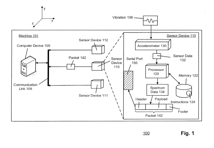
[0013] Fig. 1 illustrates an example system that may implement an embedded
system for
vibration detection and analysis, arranged in accordance with at least some
embodiments
presented herein. System 100 may be implemented on a machine 101, where
machine 101 may
be an aircraft, a rotorcraft, or a machine, that includes a computer device
105. In an example,
computer device 105 may be a legacy device that may be deemed as outdated, or
may lack
particular capabilities such as processing power, speed, memory capacity,
computational
functionalities, and/or other capabilities. In an example, computer device 105
may be a master
control unit (MCU) of a rotorcraft (e.g. machine 101). System 100 may include
computer device
105 and one or more sensor devices, such as sensor devices 110, 111, 112.
Sensor devices 110,
111, 112 may be configured to be in communication with computer device 105
through a
communication connection or communication link, such as a communication link
109. Sensor
devices 110, 111, 112 may each be an individual embedded system comprising
sensing and
processing components embedded on the same printed circuit board. Some
examples of sensing
components may include sensors operable to detect motion and/or vibrations,
such as an
accelerometer. Some examples of processing components may include
microprocessors,
microcontrollers, and/or other types of processing components or elements.
Communication link
109 may be a standardized communication connection, link or bus (e.g.,
communication bus that
may be used to transmit packets of a specific format). For example, a protocol
of
communication link 109 may be an industry standard communication protocol,
such as a
controller area network (CAN) bus, Ethernet, RS-232, or a RS-485 bus, and/or
other
standardized serial communication bus. Sensor devices 110, 111, 112 may be
located at
different locations of machine 101. For example, if machine 101 is a
rotorcraft, sensor devices
4
CA 03122369 2021-06-07
WO 2020/118130 PCT/US2019/064821
110, 111, 112, and/or additional sensor devices may be located, for example,
in proximity to a
seat of a pilot, in the cockpit, in proximity to an engine, along a tail of
the rotorcraft, in proximity
to the tail rotor, and/or other locations on the rotorcraft.
[0014] Each sensor among sensor devices 110, 111, 112 may include similar
components. Using
sensor device 110 as an example, sensor device 110 may include a processor
120, a memory 122,
an accelerometer 130, and/or a serial port 150, where processor 120 may be a
microprocessor.
Memory 122 may be configured to store a set of instructions 124, where
instructions 124 may be
a set of executable instruction including executable code. Instructions 124
may be executed by
processor 120. Instructions 124 may be associated with vibration analysis such
as Discrete Time
Fourier Transform (DTFT), Fast Fourier Transform (FFT) algorithms, magnitude
and phase
spectrum analysis techniques, filtering or windowing techniques, and/or other
algorithms and
techniques relating to time domain analysis and/or frequency domain analysis.
Serial port 150
may be a serial communication interface effective to transmit data into, or
out of, sensor device
110 serially (e.g., one bit at a time). Memory 122 may be further configured
to store serial bus
communication protocols of communication link 109, including a format of
packets that may be
transmitted using communication link 109. Accelerometer 130 may be a device
configured to
detect acceleration forces caused by vibrations being experienced by machine
101, or a portion
of machine 101. In some examples, the accelerometer 130 may be configured to
detect
acceleration forces caused by vibrations in real-time, such as vibrations
being experienced by
machine 101 during an operation of machine 101. In some examples, sensor
device 110 may be
housed in a mountable enclosure with a pigtail harness connected to a
connector that facilitates
power transmission and serial communication through serial port 150. In some
examples, sensor
device 110 may further include regulators configured to accept a variety of
alternating current
(AC) or direct current (DC) input power signals.
[0015] In an example, machine 101 may experience a vibration 106, where
vibration 106 may
cause machine 101 to experience acceleration forces in one or more directions,
such as directions
in a three-dimensional Cartesian coordinate system (e.g., x, y, z directions).
In some examples,
accelerometer 130 may be a triple-axes accelerometer configured to detect
acceleration forces in
three directions (e.g., x, y, z directions). In an example, accelerometer 130
may be a micro
electromechanical system (MEMS) including components such as cantilever beam
with a
CA 03122369 2021-06-07
WO 2020/118130 PCT/US2019/064821
seismic mass. Accelerometer 130 may be configured to detect the acceleration
forces caused by
vibration 106 by detecting motion of the components of accelerometer caused by
the acceleration
forces. Accelerometer 130 may transform the detected acceleration forces, or
detected motion,
into electrical signals represented as sensor data 132, where sensor data 132
may include data
represented in a time domain (e.g., magnitude of the signals over a range of
times).
Accelerometer 130 may send sensor data 132 to processor 120.
[0016] Processor 120 may receive sensor data 132 and may execute FFT
algorithms among
instructions 124 to transform sensor data 132 into spectrum data 134, where
spectrum data 134
may include data in a frequency domain. For example, sensor data 132 may
include data
representing magnitude of the signals of vibration 106 over a range of times,
and spectrum data
134 transformed from sensor data 132 may include data representing magnitudes
of the signals
of vibration 106 over a range of frequencies. In some examples, processor 120
may also execute
FFT algorithms to transform sensor data 132 into spectrum data that represents
other attributes of
vibration 106, such as a phase spectrum that may indicate a direction of
vibration 106.
[0017] In an example, processor 120 may be configured to sample sensor data
132 at one or
more sampling rates, transform the sampled sensor data 132 into spectrum data
134, and perform
a spectrum analysis (e.g., analysis in the frequency domain) on spectrum data
134. Processor
120 may identify one or more attributes of vibration 106 based on the spectrum
analysis on
spectrum data 134, such as a frequency in which a maximum magnitude of
vibration 106 occurs,
a phase of vibration 106, and/or other attributes of vibration 106. Processor
120 may be
configured to generate one or more packets, such as a packet 142, in a format
specific to the
serial communication protocol of communication link 109. For example,
processor 120 may
generate packet 142 in a format based on a protocol of a CAN bus if
communication link 109 is a
CAN bus.
[0018] Processor 120 may insert the results of the spectrum analysis (e.g.,
identified frequency
corresponding to a maximum magnitude, phase of vibration 106) into a payload
of packet 142.
Processor 120 may transmit packet 142 to computer device 105 through serial
port 150 and
communication link 109. Computer device 105 may receive packet 142, and may
read the
results of the spectrum analysis (the payload) from packet 142. Computer
device 105 may use
the results of the spectrum analysis to operate machine 101. For example,
computer device 105
6
CA 03122369 2021-06-07
WO 2020/118130 PCT/US2019/064821
may control various damping components of machine 101 based on the results of
the spectrum
analysis to counteract vibration 106 being experienced by machine 101 (further
described
below).
[0019] Fig. 2 illustrates an example implementation of the system 100 of Fig.
1, arranged in
accordance with at least some embodiments presented herein. Fig. 2 may include
components
that are labeled identically to components of Fig. 1, which will not be
described again for the
purposes of clarity. The description of Fig. 2 may reference at least some of
the components of
Fig. 1.
[0020] In an example shown in Fig. 2, generation of sensor data 132 may
include generation of
sensor data 202, 204, 206, corresponding to acceleration forces caused by
vibration 106 in x-
direction, y-direction, and z-direction, respectively. Sensor data 202, 204,
206 may each include
continuous-time signals. Processor 120 may be configured to sample sensor data
202, 204, 206,
using one or more different sampling rates. Focusing on sensor data 206 as an
example,
processor 120 may sample sensor data 206 at a sampling rate Si to generate
sampled data 208,
and may sample sensor data 206 at a sampling rate S2 to generate sampled data
209. Processor
120 may execute FFT algorithms (among instructions 124) to transform sampled
data 208, 209,
into spectrum data 220, 222, respectively. Spectrum data 220, 222 may each
correspond to
magnitudes of acceleration forces of vibration 106 over a range of
frequencies. Each spectrum
data (e.g., spectrum data 220, 222) may include one or more frequency bins (or
bins), and each
bin may correspond to a range of frequencies among the spectrum data. The bins
among the
spectrum data 220, 222 may be of equal width (e.g., a width being a number of
frequencies).
Processor 120 may be configured to execute spectrum analysis on spectrum data
220, 222.
[0021] Each sampled data 208, 209, may include a number of points sampled from
sensor 106 at
sampling rates Si, S2, respectively. Different sampling rates may result in
processor 120
sampling sensor data 206 at different time intervals, and may result in
different number of points
being generated for each piece of sampled data. The time interval in which
sensor data 206 is
sampled may correspond to a frequency interval, or a width of frequency bins,
in a piece of
corresponding spectrum data. For example, spectrum data 220, 222 may each
correspond to a
range of frequencies, such as, from 0 Hertz (Hz) to 1024 Hz. In the example
shown in Fig. 2,
sampling rate S2 may be greater than sampling rate Si, such that sampled data
208 may include
7
CA 03122369 2021-06-07
WO 2020/118130 PCT/US2019/064821
more points than sampled data 209. Further, due to sampling rate S2 being
greater than sampling
rate Si, a time interval between points in sampled data 208 may be less than
the time interval
between points in sampled data 209. Furthermore, due to sampling rate S2 being
greater than
sampling rate Si, a width of each bin among spectrum data 222 may be greater
than a width of
each bin among spectrum data 220. For example, Si may be 4096 Hz and S2 may be
8192 Hz. If
a FFT size (e.g., a desired number of frequency bins) is 1024, then a width of
each bin among
spectrum data 220 is 4 Hz (4096 Hz/1024), and a width of each bin among
spectrum data 222 is
8 Hz (8192 Hz/1024).
[0022] Thus, processor 120 may adjust a frequency resolution of spectrum data
resulting from an
application of FFT. In some examples, the sampling rate used by processor 120
to sample sensor
data 206 may be application specific, such as being based on a frequency
spectrum window and
a bin resolution associated with different applications. In an example, the
sampling rate defines
the frequency spectrum window (e.g., a range of frequencies) to be monitored
in a spectrum
analysis. Thus, a relatively lower sampling rate may limit a range of
frequencies being
monitored, but may also increase the bin resolution. For example, if processor
120 samples
sensor data 206 using Si and S2, at a fixed FFT size (e.g., a desired number
of bins), the range of
frequencies in spectrum data 220 may be half the range of frequencies in
spectrum data 222. In
some examples, using a relatively low sampling rate may lead to sampling
sensor data 206 for a
longer period of time, which may decrease a response time for processor 120 to
complete the
transformation of sensor data 206 into spectrum data. For example, if a range
of times or
frequencies to be analyzed by processor 120 is fixed, processor 120 may need
to use more time
to transform sampled data 208 into spectrum data 220 when compared to
transformation of
sampled data 209 into spectrum data 222 (due to sampled data 208 including
more points). In
an example, a vibration damping component of machine 101 may be implemented to
focus on
attenuation of vibrations at a relatively low range of frequencies, such as
20hz to 30hz.
Therefore, processor 120 may sample sensor data 206 at a relatively low rate
to improve the bin
resolution the frequency range 20hz to 30hz. Further a FFT size may impact the
range of
frequencies defined by the frequency spectrum window.
[0023] In the example shown in Fig. 2, the width of bins among spectrum data
220 is less than
the width of bins among spectrum data 222. The difference between the
frequency resolutions of
8
CA 03122369 2021-06-07
WO 2020/118130 PCT/US2019/064821
spectrum data 220 and spectrum data 222 may be shown by a section 220x of
spectrum data 220
and a section 222x of spectrum data 222. Section 220x includes a presence of
three bins (bins
221a, 221b, 221c) representing magnitudes of vibration 106 at frequencies F1-
w1, F1, Fi+wi in
spectrum data 220, respectively, where wi is a width of the bins in spectrum
data 220. Section
222x includes a presence of two bins (bins 224a, 221b) representing magnitudes
of vibration 106
at frequencies F2, F2-FW2 in spectrum data 222, respectively, where w2 is a
width of the bins in
spectrum data 222. Thus, spectrum data 220 has a higher frequency resolution
than spectrum
data 222, and decreasing the sampling rate (at a fixed FFT size) may increase
the frequency
resolution. In another example, if a sampling rate is fixed, an increase in
the FFT size would
increase the frequency resolution.
[0024] In an example, processor 120 may further determine that a difference
between an
amplitude (magnitude) of a bin 225 corresponding to frequency F2-w2 and an
amplitude of bin
224a, is greater than a threshold that may be defined and stored in memory
122. When the
difference between bin 225 and bin 224a is greater than the threshold, there
is an implication of a
presence of frequency leak. Processor 120, in response to the difference being
greater than the
threshold, may sample sensor data 206 at a lower sampling rate, such as Si, to
obtain spectrum
data of higher frequency resolution. Thus, processor 120 may be configured to
sample spectrum
data with different sampling rates in order to improve frequency resolution of
the spectrum data
and to reduce the potential risk of frequency leak during sampling in an
execution of spectrum
analysis. In an example, processor 120 may toggle the bin resolution during
the spectrum
analysis. For example, processor 120 may start with an initial sampling rate
to generate
spectrum data for a specific application, and may decrease the sampling rate
to improve the bin
resolution when required by the specific application.
[0025] Processor 120 may identify specific attributes of vibration 106 based
on spectrum data
220, 222. In an example, processor 120 may identify frequency F1 that
corresponds to a
maximum magnitude being indicated by spectrum data 220. In another example,
processor 120
may determine a power spectral density of vibration 106 for each spectrum data
220, 222, where
the power spectral densities may characterize random vibration signals among
vibration 106.
Processor 120 may determine the power spectral density by, for example,
multiplying each bin
among the spectrum data by its complex conjugate. Processor 120 may generate
packets 240a,
9
CA 03122369 2021-06-07
WO 2020/118130 PCT/US2019/064821
240b, 240c corresponding to spectrum data transformed from sensor data 202,
204, 206,
respectively. Each packet among packets 240a, 240b, 240c may include one or
more attributes
of vibration 106, as a payload, in a corresponding direction (e.g., x, y, z-
directions). Processor
120 may send packets 240a, 240b, 240c to serial port 150, such that sensor
device 110 may
transmit packets 240a, 240b, 240c, sequentially, to computer device 105
through communication
link 109. Thus, sensor device 110 may provide results of the spectrum analysis
to computer
device 105 in order for computer device 105 to operate the machine housing
computer device
105 and sensor device 110 based on the results of the spectrum analysis.
[0026] In another example, spectrum data 220 may be divided or partitioned
into one or more
sections, such as sections 220a, 220x. Each section of spectrum data 220 may
include a
particular number of bins. For example, if spectrum data 220 ranges from 0 Hz
to 1023 Hz,
spectrum data 220 may include sixteen sections (including 220a, 220x), where
each section of
spectrum data 220 includes sixteen frequency bins due to sensor data 206 being
sampled using
sampling rate S1 (each section spans a range of 64 Hz, and each bin of each
section having a
width of 4 Hz). Processor 120 may insert each section of spectrum data 220
into a respective
packet as a payload. Thus, if spectrum data 220 includes sixteen sections,
processor 120 may
generate sixteen packets for spectrum data 220, each packet including a
section of spectrum data
220 as a payload. The sixteen packets may be transmitted to computer device
105 through serial
port 150 and communication link 109. Computer device 105 may receive the
sixteen packets
and may perform analysis or comparisons on the sixteen packets in order to
perform particular
tasks or operations relating to operations of machine 101. In some examples,
partitioning
spectrum data 220 into different sections may be based on a specific
application of system 100.
Computer device 105 may be configured to send one or more application
parameters to sensor
device 110, where the application parameters may be specific to the specific
application. For
example, a motor of machine 101 may be vulnerable to failure if vibrations of
a particular range
of frequencies, with particular magnitudes, are applied to the motor. Computer
device 105 may
send the particular range of frequencies, the particular magnitudes, data
capture information and
procedures, and/or other information relating to monitoring a health of the
motor. Sensor device
110 may be located in proximity to the motor of machine 101 to monitor
amplitudes of
vibrations at the particular range of frequencies applied at locations in
proximity to the motor.
CA 03122369 2021-06-07
WO 2020/118130 PCT/US2019/064821
Processor 120 may partition spectrum data 220 into different sections, such
that at least one
section corresponds to the particular range of frequencies. If amplitudes of
the bins within the
sections corresponding to the particular range of frequencies exceed a
predefined threshold, then
there is a risk of damages or failures of the motor. Thus, processor 120 may
generate a message
indicating a health of the motor, such as messages stating "healthy" or "not
healthy", and may
insert the message into the payload of a packet to be transmitted to computer
device 105.
[0027] In an example, computer device 105 may receive sections 220a and 220x
of spectrum
data 220. Computer device 105 may analyze the bins among section 220a, such as
comparing
the amplitudes of the bins within section 220a with each other, and may
determine that
amplitudes of the bins among section 220a are substantially similar (e.g.,
amplitude difference
between each pair of bins being below a threshold value). Computer device 105
may analyze the
bins among section 220x and may determine that amplitudes of bins 221a, 221b,
221c are
significantly greater than amplitudes of other bins within section 220x (e.g.,
amplitude difference
between bins 221a, 221b, 221c and other bins in section 220x being greater
than a threshold
value). Based on the determination that section 220x includes one or more bins
with amplitudes
significantly greater than other bins within section 220x, computer device 105
may identify a bin
with a largest amplitude in section 220x. In the example shown in Fig. 2,
computer device 105
may identify bin 221b has the largest amplitude among the amplitudes of the
bins of section
220x, and frequency F1 corresponds to bin 221b. Computer device 105 may
identify frequency
F1 as a critical frequency caused by acceleration forces, in the z-direction,
of vibration 106.
[0028] Computer device 105 may operate components of machine 101 based on the
identified
frequency F1. For example, computer device 105 may be configured to adjust a
position of a
weight on a tuned mass damper located in or on machine 101. Each position of
the weight on the
tuned mass damper may attenuate a different vibration frequency. A mapping
between a
plurality of positions of the weight and the different vibration frequencies
may be stored in a
memory of machine 101. Computer device 105 may be configured to perform a
lookup function
on the stored mapping to identify a position of the weight that is mapped to
frequency F1.
Computer device 105 may adjust the weight to the identified position to
attenuate vibration 106.
[0029] In an example, more than one sensor devices, such as sensor devices
110, 111, 112 may
communicate respective packets including spectrum analysis results to computer
device 105
11
CA 03122369 2021-06-07
WO 2020/118130 PCT/US2019/064821
through communication link 109. Thus, in an example where sensor devices 110,
111, 112 are
located at different locations within a machine such as a rotorcraft, each
sensor device may be
configured to output respective spectrum analysis results indicating vibration
effects to different
locations of the rotorcraft. In some examples, an order in which the sensor
devices 110, 111,
112, transmit respective spectrum analysis results to computer device 105 may
be based on the
protocol of communication link 109. For example, if communication link 109 is
a CAN bus, the
order in which sensor devices 110, 111, 112 transmit data to computer device
105 may be based
on an arbitration scheme of a protocol of a CAN bus. Thus, using a
standardized serial
communication bus may allow sensor devices 110, 111, 112, to transmit
respective spectrum
analysis results to computer device 105 in an organized manner. Further, the
sensor devices in
accordance with the present disclosure may be relocated to different locations
among the
machine, in order to provide a flexible network of vibration sensor devices on
the machine.
[0030] Fig. 3 illustrates a flow diagram relating to a process to implement an
adaptive tuned
mass absorber, arranged in accordance with at least some embodiments presented
herein. The
process in Fig. 3 may be implemented using, for example, system 100 discussed
above. An
example process may include one or more operations, actions, or functions as
illustrated by one
or more of blocks S2, S4, S6, S8, S10, and/or S12. Although illustrated as
discrete blocks,
various blocks may be divided into additional blocks, combined into fewer
blocks, eliminated, or
performed in parallel, depending on the desired implementation.
[0031] The processing may begin at block S2, "Detect acceleration forces
caused by a vibration".
A block S2, A sensor device may detect acceleration forces caused by a
vibration.
[0032] The processing continues from block S2 to block S4, "Transform the
acceleration forces
into sensor data represented in a time domain". At block S4, the sensor device
may transform
the acceleration forces into sensor data represented in a time domain.
[0033] The processing may continue from block S4 to block S6, "Transform the
sensor data into
spectrum data represented in a frequency domain". At block S6, The sensor
device may
transform the sensor data into spectrum data represented in a frequency
domain.
[0034] The processing may continue from block S6 to block S8, "Execute a
spectrum analysis on
the spectrum data". At block S8, the sensor device may execute a spectrum
analysis on the
spectrum data. The execution of the spectrum analysis on the spectrum data may
include
12
CA 03122369 2021-06-07
WO 2020/118130 PCT/US2019/064821
sampling the spectrum data at a sampling rate. The sensor device may further
adjust a frequency
resolution of the spectrum data by sampling the spectrum data at a different
sampling rate.
[0035] The processing may continue from block S8 to block S10, "Generate a
packet that
comprises a result of the spectrum analysis as a payload of the packet". At
block S10, the sensor
device may generate a packet that comprises a result of the spectrum analysis
as a payload of the
packet. A format of the packet may be based on a protocol of a communication
link between the
sensor device and the computer device. In some examples, the communication
link may be a
controller area network (CAN) bus.
[0036] The processing may continue from block S10 to block S12, "Send the
packet to the
computer device through a communication link". At block S12, the sensor device
may send the
packet to the computer device through the communication link.
[0037] The terminology used herein is for the purpose of describing particular
embodiments only
and is not intended to be limiting of the invention. As used herein, the
singular forms "a", "an"
and "the" are intended to include the plural forms as well, unless the context
clearly indicates
otherwise. It will be further understood that the terms "comprises" and/or
"comprising," when
used in this specification, specify the presence of stated features, integers,
steps, operations,
elements, and/or components, but do not preclude the presence or addition of
one or more other
features, integers, steps, operations, elements, components, and/or groups
thereof.
[0038] The corresponding structures, materials, acts, and equivalents of all
means or step plus
function elements, if any, in the claims below are intended to include any
structure, material, or
act for performing the function in combination with other claimed elements as
specifically
claimed. The description of the present invention has been presented for
purposes of illustration
and description, but is not intended to be exhaustive or limited to the
invention in the form
disclosed. Many modifications and variations will be apparent to those of
ordinary skill in the
art without departing from the scope and spirit of the invention. The
embodiment was chosen
and described in order to best explain the principles of the invention and the
practical
application, and to enable others of ordinary skill in the art to understand
the invention for
various embodiments with various modifications as are suited to the particular
use contemplated.
13