Note: Descriptions are shown in the official language in which they were submitted.
BRACE LIMITING RANGE OF MOTION AND METHOD OF USING SAME
CROSS-REFERENCE TO RELATED APPLICATIONS
[0001] This application claims priority to U.S. Provisional Application
No. 62/782,707,
filed on December 20, 2018.
BACKGROUND
Field of the Disclosure
[0002] The present disclosure relates generally to a brace configured to
limit a range of
motion of a joint of a user and a method of using the same.
Description of the Related Technology
[0003] Damaged ligaments, cartilage, and tendons in joints are not an
uncommon
occurrence, particularly with today's emphasis on physical activity and
conditioning. Few injuries
interfere with motion more than injuries to the knee. Knee injuries account
for approximately 60%
of all sports related injuries with nearly half of those injuries occurring to
the ACL. ACL injury
is most prevalent (1 in 1,750 persons) in patients between the ages of 15 and
45, due in no small
measure to their more active lifestyle as well as higher participation in
sports. A person who has
tom their ACL has a 15 times greater risk of a second ACL injury during the
initial 2 months after
ACL reconstruction, and risk of ACL injury to the opposite knee is two times
that of the
restructured knee.
[0004] There are four main ligaments which hold the knee together:
Anterior Cruciate
Ligament (ACL), Posterior Cruciate Ligament (PCL), Medial Collateral Ligament
(MCL) and
Lateral Collateral Ligament (LCL). There are over 200,000 ACL injuries that
occur in the United
States annually. Approximately 50% of ACL injuries occur with injuries to
other structures of the
knee. While less common than an ACL injury, injuries to the PCL account for
between 3% to
20% of all knee ligament injuries. The collateral ligaments, MCL and LCL, are
responsible for
25% of knee injuries in competitive athletes.
[0005] Treatments for ACL and other ligament injuries include surgical and
non-surgical
options. Braces are employed to limit range of motion, promote support and
stabilization while
-1-
Date Recue/Date Received 2023-01-13
CA 03122550 2021-06-08
WO 2020/131636 PCT/US2019/066334
ligaments heal. In the case of ACL surgery, graft strength of a new ACL is
considerably weaker
than the native ACL during the first 12 months, so a brace configured to limit
the range of motion
of a joint of the user during this early period helps protect it from harmful
forces that occur in
everyday life or in sports activity.
SUMMARY
[0006] According to some embodiments, a brace configured to restrict a
range of motion
of a joint of a subject is provided. The brace includes an upper support arm.
The brace includes a
lower support arm. The brace includes a hinge assembly. The hinge assembly
includes an upper
hinge plate coupled to the upper support arm and comprising a first plurality
of teeth disposed
along at least a portion of a perimeter of the upper hinge plate. The hinge
assembly includes a
lower hinge plate coupled to the lower support arm and comprising a second
plurality of teeth
disposed along at least a portion of a perimeter of the upper hinge plate. The
hinge assembly
includes an axle rotatably coupling the upper hinge plate and the lower hinge
plate. The hinge
assembly includes a locking element disposed on the upper hinge plate. The
locking element
includes a first protrusion and a second protrusion configured to physically
contact opposite sides
of one of the second plurality of teeth in a first orientation, thereby
prohibiting rotation of the upper
support arm with respect to the lower support arm.
[0007] According to some embodiments, a method of restricting a range of
motion of a
joint of a subject utilizing a brace configured for attachment to the joint is
provided. The method
includes securing an upper support arm of the brace against an upper portion
of an appendage of
the subject. The method includes securing a lower support arm of the brace
against a lower portion
of the appendage. The method includes restricting a range of motion of the
upper support arm with
respect to the lower support arm utilizing a hinge assembly of the brace. The
hinge assembly
includes an upper hinge plate coupled to the upper support arm and comprising
a first plurality of
teeth disposed along at least a portion of a perimeter of the upper hinge
plate. The hinge assembly
includes a lower hinge plate coupled to the lower support arm and comprising a
second plurality
of teeth disposed along at least a portion of a perimeter of the upper hinge
plate. The hinge
assembly includes an axle rotatably coupling the upper hinge plate and the
lower hinge plate. The
hinge assembly includes a locking element disposed on the upper hinge plate,
the locking element
comprising a first protrusion and a second protrusion configured to physically
contact opposite
-2-
CA 03122550 2021-06-08
WO 2020/131636 PCT/US2019/066334
sides of one of the second plurality of teeth in a first orientation, thereby
prohibiting rotation of
the upper support arm with respect to the lower support arm.
[0008] According to some embodiments, a method of manufacturing a brace
configured to
restrict a range of motion of a joint of a subject is provided. The method
includes providing an
upper support arm. The method includes providing a lower support arm. The
method includes
assembling a hinge assembly. Assembling the hinge assembly includes coupling
an upper hinge
plate to the upper support arm, the upper hinge plate comprising a first
plurality of teeth disposed
along at least a portion of a perimeter of the upper hinge plate. Assembling
the hinge assembly
includes coupling a lower hinge plate to the lower support arm, the lower
hinge plate comprising
a second plurality of teeth disposed along at least a portion of a perimeter
of the upper hinge plate.
Assembling the hinge assembly includes rotatably coupling the upper hinge
plate and the lower
hinge plate via an axle. Assembling the hinge assembly includes disposing a
locking element on
the upper hinge plate. The locking element includes a first protrusion and a
second protrusion
configured to physically contact opposite sides of one of the second plurality
of teeth in a first
orientation, thereby prohibiting rotation of the upper support arm with
respect to the lower support
arm.
BRIEF DESCRIPTION OF THE DRAWINGS
[0009] FIG. 1 illustrates a brace configured for attachment to a joint of
a user, in
accordance with some embodiments;
[0010] FIG. 2A illustrates a hinge assembly of the brace of FIG. 1, in
accordance with
some embodiments;
[0011] FIG. 2B illustrates the hinge assembly FIG. 2A further comprising
a window
configured to provide visual indication of a locked state of the hinge
assembly, in accordance with
some embodiments;
[0012] FIG. 3A illustrates a plan view of a hinge assembly of the brace
of FIG. 1 in an
unlocked configuration, in accordance with some embodiments;
[0013] FIG. 3B illustrates a perspective view of the hinge assembly of
FIG. 3A in the
unlocked configuration;
[0014] FIG. 4A illustrates a plan view of a hinge assembly of the brace
of FIG. 1 in a
locked configuration, in accordance with some embodiments;
-3-
CA 03122550 2021-06-08
WO 2020/131636 PCT/US2019/066334
[0015] FIG. 4B illustrates a perspective view of the hinge assembly of
FIG. 4A in the
locked configuration, in accordance with some embodiments;
[0016] FIG. 5A illustrates a plan view of another hinge assembly of the
brace of FIG. 1
in an unlocked configuration, in accordance with some embodiments;
[0017] FIG. 5B illustrates a plan view of the hinge of FIG. 5A in a
locked configuration;
[0018] FIG. 6 illustrates a perspective view of a locking mechanism of
the brace of FIG.
1, in accordance with some embodiments;
[0019] FIG. 7 illustrates a cutaway view of a hinge assembly of the brace
of FIG. 1,
according to some embodiments;
[0020] FIG. 8A illustrates a perspective view of a portion of the brace
of FIG. 1, according
to some embodiments;
[0021] FIG. 8B illustrates a perspective view of a lower portion of the
brace of FIG. 1 in
a maximally extended position, according to some embodiments;
[0022] FIG. 8C illustrates a perspective view of attachment of a cuff to
a support arm
according to some embodiments;
[0023] FIG. 80 illustrates the cuff of FIG. 8C separated from the support
arm;
[0024] FIG. 8E illustrates a perspective view of a lower portion of the
brace of FIG. 1 in
a minimally extended position, according to some embodiments;
[0025] FIG. 8F illustrates a perspective view of an upper portion of the
brace of FIG. 1 in
a minimally extended position, according to some embodiments;
[0026] FIG. 9A illustrates an adjustable cuff for a lower support arm
according to some
embodiments;
[0027] FIG. 9B illustrates the cuff of FIG. 9A being attached to the
lower support arm;
[0028] FIG. 9C illustrates a perspective view of a lower portion of the
brace of FIG. 1 in
a minimally extended position using the cuff of FIG. 9A, according to some
embodiments;
[0029] FIG. 90 illustrates an adjustable cuff for an upper support arm
according to some
embodiments;
[0030] FIG. 9E illustrates the cuff of FIG. 90 attached to the upper
support arm;
[00311 FIG. 9F illustrates a perspective view of an upper portion of the
brace of FIG. 1 in
a minimally extended position using the cuff of FIG. 9D, according to some
embodiments;
-4-
CA 03122550 2021-06-08
WO 2020/131636 PCT/US2019/066334
[0032] FIG. 10 illustrates a perspective view of a buckle for use with
the brace of FIG. 1,
according to some embodiments;
[0033] FIG. 11 illustrates a flowchart of a method a method of using a
brace configured
for attachment to a joint of a subject, in accordance with some embodiments;
and
[0034] FIG. 12 illustrates a flowchart of a method of a method of
manufacturing a brace
configured for attachment to a joint of a subject, in accordance with some
embodiments.
DETAILED DESCRIPTION
[0035] Embodiments of this disclosure relate to orthopedic braces for use
in treating a
variety of injuries to the knee, or other joint, and surrounding ligaments.
More particularly,
embodiments of the brace disclosed herein may be intended for use in post-
operative activities
and/or activities of daily living for patients with ACL deficiencies,
collateral ligament deficiencies,
hyperextension injury, or for prophylactic use.
[0036] Orthotic bracing and support can promote healing and wellness
through the benefit
of natural motion through safe ranges of motion (ROM) and/or by locking a
joint in a desired
orientation. Post-surgical recovery of the patient may be at least partially
dependent upon locking
the affected joint in a desired orientation and/or limiting ROM to a
predetermined safe range.
Accordingly, there is a need for bracing solutions configured to lock the
affected joint in a desired
orientation and/or limit ROM to a predetermined safe range.
[00371 A better understanding of the various features of the disclosure
can be gleaned from
the following description read in conjunction with the accompanying drawings
in which like
reference characters refer to like elements, where reasonably applicable.
While the disclosure may
be susceptible to various modifications and alternative constructions, certain
illustrative features
are shown in the drawings and are described in detail below. It will be
understood, however, that
there is no intention to limit the disclosure to the specific embodiments
disclosed, but to the
contrary, the intention is to cover all modifications, alternative
constructions, combinations, and
equivalents falling within the spirit and scope of the disclosure.
[0038] Furthermore, it will be appreciated that unless a term is
expressly defined in this
disclosure to possess a described meaning, there is no intent to limit the
meaning of such term,
either expressly or indirectly, beyond its plain or ordinary meaning.
-5-
CA 03122550 2021-06-08
WO 2020/131636 PCT/US2019/066334
[0039] For ease of understanding the disclosed features of an orthopedic
device, as used
herein, "proximal" has its ordinary meaning and refers to a location situated
next to or near the
point of attachment or origin or a central point or located toward the center
of the body. Likewise,
the term "distal" has its ordinary meaning and refers to a location that is
situated away from the
point of attachment or origin or central point or located away from the center
of the body. The
term "medial" refers to a position that is closer to the midline of the body,
whereas the term
"lateral" refers to a position further from the midline of the body. The terms
"upper" and "lower"
describe the position of certain elements as being either above or below a
hinge assembly of the
brace. An "upper" element is above the hinge assembly and knee or other joint,
whereas a "lower"
element is below the hinges assembly and knee or other joint. The term
"posterior" also has its
ordinary meaning and refers to a location that is behind or to the rear of
another location or feature.
Lastly, the term "anterior" has its ordinary meaning and refers to a location
that is ahead of or to
the front of another location or feature.
[0040] The terms "rigid," "flexible," "malleable" and "resilient" may be
used herein to
distinguish portions of certain features of the orthopedic device. The term
"rigid" is intended to
mean an element of the device is generally or substantially inflexible. Within
the context of frame
or support members or shells that are "rigid," it is intended to indicate that
they do not lose their
overall shape when force is applied. The term "flexible" or "malleable", by
contrast, is intended
to encompass features that are capable of bending or flexing under load.
[0041] FIG. 1 illustrates a brace 100 configured for attachment to a
joint of a user, in
accordance with some embodiments. Brace 100 includes at least one of lateral
portion 160
configured to abut a lateral side of an appendage of a user, and a medial
portion 170 configured to
abut a medial side of the appendage of the user. As will be described in more
detail in connection
with the following figures, lateral and medial portions 160, 170 may each
comprise an upper
support arm 102, a lower support arm 104, and a hinge assembly 106 configured
to rotatably couple
upper support arm 102 to lower support arm 104. Hinge assembly 106 is further
configured to limit
a range of motion of upper support arm 102 with respect to lower support arm
104 in at least one
of a first rotational direction and a second rotational direction. As will be
described in more detail
below, each of lateral and medial portions 160, 170 may further comprise an
upper slider 162
configured to slidably couple to upper support arm 102 and a lower slider 164
configured to
slidably couple to lower support arm 104. Brace 100 may be secured to an
appendage of a user
-6-
CA 03122550 2021-06-08
WO 2020/131636 PCT/US2019/066334
utilizing one or more straps configured to secure upper and lower support arms
102, 104 and upper
and lower sliders 162, 164 against a side of a user's appendage. Various
features, aspects and
elements of brace 100 will now be described in more detail in connection with
the following
figures.
[0042] FIG. 2A illustrates hinge assembly 106 of brace 100 of FIG. I, in
accordance with
some embodiments, while FIG. 2B illustrates hinge assembly 106 of FIG. 2A
further comprising
a window 124 configured to provide visual indication of a locked state of
hinge assembly 106, in
accordance with some embodiments. Discussion of hinge assembly 106 will be
described in
connection with FIGs. 2A and 2B together below.
[0043] The terms "hinge" or "hinge assembly" as used herein means a
mechanical coupler
that ties two arms of the brace together while allowing rotational motion
through different angular
orientations of the longitudinal axes of the two arms. For example, as shown
in FIGs. 2A and 2B,
hinge assembly 106 mechanically couples upper support arm 102 and lower
support arm 104 about
an axle 108. Upper and lower support arms 102, 104 may comprise any suitably
rigid material,
e.g., metal, plastic, fiberglass composite, etc.
[0044] Hinge assembly 106 comprises a hinge cover 110 configured to cover
at least some
internal components of hinge assembly 106 as will be described in more detail
below. When in
use, hinge assembly 106 is generally proximate to the anatomical joint being
braced, for example
and not limitation, a knee or an elbow joint. Hinge assembly 106 comprises a
first range of motion
stop 112 configured to limit a range of motion of upper support arm 102 with
respect to lower
support arm 104 in a first rotational direction. Hinge assembly 106 may
further comprise a second
range of motion stop 114 configured to limit a range of motion of upper
support arm 102 with
respect to lower support arm 104 in a second rotational direction opposite the
first rotational
direction. In some embodiments, first and second range of motion stops 112,
114 may comprise
any suitably resilient material, e.g., plastic, which in some cases may be
injection molded.
[0045] Hinge assembly 106 comprises an outer housing 116 configured to
enclose at least
some internal components of hinge assembly 106 as will be described in more
detail below. Outer
housing 116 comprises one or more fasteners 118 configured to secure outer
housing 116 to hinge
assembly 106. In some embodiments, fasteners 118 may be rivets, screws, or any
other suitable
fastening element(s). Outer housing 116 further comprises an aperture 120
within which a hinge
lock 122 is configured to slide. Hinge lock 122 is configured to lock hinge
assembly 106 in a
-7-
CA 03122550 2021-06-08
WO 2020/131636 PCT/US2019/066334
desired orientation about axle 108 when the hinge lock 122 is positioned in a
first orientation (e.g.,
a locked orientation). The hinge lock 122 is configured to allow hinge
assembly 106 to move freely
about axle 108 within the range of motion set by first and second range of
motion stops 112, 114
when hinge lock 122 is positioned in a second orientation (e.g., an unlocked
orientation). In some
embodiments, hinge lock 122 may comprise a slider, a button, or any other
suitable element
configured to slide, toggle, or shift between the first orientation and the
second orientation within
aperture 120. In some embodiments, the first orientation may be more proximal
to axle 108, within
aperture 120, compared to the second orientation.
[00461 In some embodiments, as shown in FIG. 2B, hinge cover 110
comprises window
124 configured to provide visual indication of a locked state of hinge
assembly 106. For example,
a portion of hinge lock 122 may be visible through window 124 when hinge lock
122 is in the first
orientation, thereby indicating hinge assembly 106 is in a locked state. In
such embodiments, the
same portion of hinge lock 122, visible through window 124 when hinge lock 122
is in the first
orientation, is not visible through window 124 when hinge lock 122 is in the
second orientation,
thereby indicating hinge assembly 106 is not in the locked state. In some
embodiments, at least the
portion of hinge lock 122, visible through window 124 when hinge lock 122 is
in the first
orientation, has an easily noticeable color, e.g., red or orange, or other
pattern, thereby providing
an easily noticeable indication to a user when hinge assembly 106 is in a
locked state.
[0047] FIG. 3A illustrates a plan view of hinge assembly 106 of the brace
of FIG. 1 in an
unlocked configuration, in accordance with some embodiments, while FIG. 3B
illustrates a
perspective view of hinge assembly 106 of FIG. 3A in the unlocked
configuration. FIG. 4A
illustrates a plan view of hinge assembly 106 of the brace of FIG. 1 in a
locked configuration, in
accordance with some embodiments, while FIG. 4B illustrates a perspective view
of hinge
assembly 106 of FIG. 4A in the locked configuration. FIGs. 3A-4B illustrate
hinge assembly 106
with hinge cover 110 and outer housing 116 removed for easy viewing of
components located
thereunder.
[0048] Hinge assembly 106 comprises an upper hinge plate 126 coupled to
upper support
arm 102 utilizing any suitable coupling element(s), for example rivets, screws
or welds. At least a
portion of upper hinge plate 126 has a substantially circular perimeter
centered about axle 108. At
least a portion of the substantially circular perimeter comprises a plurality
of teeth 128. In some
-8-
CA 03122550 2021-06-08
WO 2020/131636 PCT/US2019/066334
embodiments, upper hinge plate 126 and upper support arm 102 may be formed as
a single, integral
component.
[0049] Hinge assembly 106 comprises a lower hinge plate 130 coupled to
lower support
arm 104 utilizing any suitable coupling element(s), for example rivets, screws
or welds. At least a
portion of lower hinge plate 130 has a substantially circular perimeter
centered about axle 108. At
least a portion of the substantially circular perimeter comprises a plurality
of teeth 132. In some
embodiments, lower hinge plate 130 and lower support arm 104 may be formed as
a single, integral
component. Upper and lower hinge plates 126, 130 may comprise any suitably
rigid material, e.g.,
metal, plastic, fiberglass composite, etc.
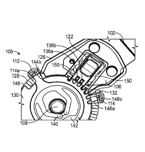
[0050] In the embodiment of FIGS. 3A and 3B, the hinge lock 122 comprises
a body in
the foiiii of an open frame with a top panel, a partially open bottom panel,
and legs extending
therebetween, which may be made of a plastic material. The partially open
bottom panel is defined
by feet 150 extending between pairs of legs. A first protrusion 136a and a
second protrusion 136b
are formed by two pins, which may be made of metal. The pins are press fit
through aligned
openings provided in the top panel and the bottom panel of the hinge lock
frame. The centers of
the pins are exposed between the top panel and the bottom panel of the hinge
lock frame so they
can engage teeth 132. In some advantageous embodiments, the location of the
hinge lock in the
housing is such that allows teeth 132 to be centrally located on the lower
hinge plate 130 so the
same stamping tool can be used to form both the left and right lower bars.
[0051] When locking mechanism 122 is in the second, unlocked orientation
as shown in
FIGs. 3A and 3B, first and second protrusions 136a, 136b are not in contact
with the plurality of
teeth 132 of lower hinge plate 130 and upper support arm 102 and lower support
arm 104 are free
to rotate with respect to one another about axle 108, within a range of motion
set by the positions
of first and second range of motion stops 112, 114.
[0052] However, when locking mechanism 122 is in the first, locked
orientation as shown
in FIGs. 4A and 4B, first and second protrusions 136a, 136b are configured to
physically contact
opposite sides of one of the plurality of teeth 132 of lower hinge plate 130,
thereby prohibiting
rotation of hinge assembly 106 and locking upper support arm 102 with respect
to lower support
arm 104 in a desired orientation. An orientation of the plurality of teeth 132
of lower hinge plate
130 with respect to hinge lock 122, insert 134 and first and second
protrusions 136a, 136b may be
such that the same designs for lower hinge plate 130, hinge lock 122, insert
134 and first and
-9-
CA 03122550 2021-06-08
WO 2020/131636 PCT/US2019/066334
second protrusions 136a, 136b may be utilized on any of a lateral or medial
side of a joint located
on either a left or right side of the user's body. For example, the plurality
of teeth 132 may extend
radially outward from a point coincident with a center of axle 108 and the
first and second
orientations of hinge lock 122 may both lie along a straight line extending
away from the same
point coincident with a center of axle 108. Accordingly, a single design for
components of hinge
assembly 106 may be utilized on each of the medial and lateral sides of a
brace for either a left or
a right joint, thereby reducing part count, as well as design and
manufacturing costs.
[0053] First and second range of motion stops 112, 114 may have
substantially similar
structure and functionality and will, therefore, now be described together in
connection with FIGs.
3A-4B. First range of motion stop 112 is disposed between hinge cover 110 and
lower hinge plate
130, while second range of motion stop 114 is disposed between lower hinge
plate 130 and upper
hinge plate 126.
[0054] First range of motion stop 112 comprises a first protrusion 144a
and a second
protrusion 144b configured to physically contact opposite sides of one of the
plurality of teeth 128
of upper hinge plate 126 when first range of motion stop 112 is in a locked
position, thereby
immobilizing first range of motion stop 112 at a first desired position along
the perimeter of upper
hinge plate 130. In some embodiments, hinge cover 110 (see FIGs. 2A, 2B) may
comprise a
plurality of teeth similar to the plurality of teeth 128 of upper hinge plate
126 such that first and
second protrusions 144a, 144b also physically contact opposite sides of one of
the plurality of teeth
of hinge cover 110 when first range of motion stop 112 is in the locked
position. Although FIG.
3A does not show the side of first range of motion stop 112 that contacts
upper hinge plate 126,
first and second protrusions 144a, 144b extend sufficiently toward upper hinge
plate 126 to
physically contact the plurality of teeth 128 as described above.
[0055] First range of motion stop 112 is configured to be pulled in a
radial direction with
respect to axle 108, such that first and second protrusions 144a, 144b clear
the plurality of teeth
128, and then rotated to the first desired position. First range of motion
stop 112 comprises a
plurality of retention arms 140 configured to contact axle 108 such that, when
first range of motion
stop 112 is pulled in the radial direction, axle 108 deflects the plurality of
retention arms 140 in an
outward direction, thereby providing a restoring force that returns first
range of motion stop 112
to the locked position when released. In some embodiments, first range of
motion stop 112 may
also comprise a backstop element 142 configured to contact axle 108 when first
range of motion
-10-
CA 03122550 2021-06-08
WO 2020/131636 PCT/US2019/066334
stop 112 is pulled sufficiently far in the radial direction, thereby
preventing hyperextension of first
range of motion stop 112 or of the plurality of retention arms 140. When in
the locked position,
first range of motion stop 112 limits the range of motion of upper support arm
102 with respect to
lower support arm 104 in a first rotational direction by coming into contact
with a first portion 146
of lower hinge plate 130.
[00561 First range of motion stop 112, including the plurality of
retention arms 140 and
backstop element 142, may be integrally molded as a single part, for example,
by injection
molding. Integrally molding first range of motion stop 112 as a single part
eliminates part count
and reduces both manufacturing and assembly costs due to labor and/or non-
conformity issues that
can occur when assembling separate parts. In addition, first range of motion
stop 112 may be
designed for injection molding such that its molding doesn't require any side
action in the tooling.
For example, all sides of first range of motion stop 112 may be substantially
perpendicular to a
plane of first range of motion stop 112, or may slope to one side or the other
of perpendicular (but
not both at any given point along the sides), so that side molds are not
required to allow clearance
of stop 112 from its injection mold. This not only reduces tool cost and
complexity, it also lowers
part cost through faster manufacture cycle time compared to other designs in
which side action in
the tooling is required to remove a part from its injection mold.
[00571 Second range of motion stop 114 comprises a first protrusion 148a
and a second
protrusion 148b configured to physically contact opposite sides of one of the
plurality of teeth 128
of upper hinge plate 126 when second range of motion stop 114 is in a locked
position, thereby
immobilizing second range of motion stop 114 at a second desired position
along the perimeter of
upper hinge plate 126. Where hinge cover 110 (see FIGs. 2A, 2B) comprises a
plurality of teeth
similar to the plurality of teeth 128 of upper hinge plate 126, first and
second protrusions 148a,
148b also physically contact opposite sides of one of the plurality of teeth
of hinge cover 110 when
second range of motion stop 114 is in the locked position. Although FIG. 3A
does not show the
side of second range of motion stop 114 that contacts upper hinge plate 126,
first and second
protrusions 148a, 148b extend sufficiently toward upper hinge plate 126 to
physically contact the
plurality of teeth 128 as described above.
[00581 Second range of motion stop 114 is configured to be pulled in a
radial direction
with respect to axle 108, such that first and second protrusions 148a, 148b
clear the plurality of
teeth 128, and then rotated to the second desired position. Second range of
motion stop 114
-11-
CA 03122550 2021-06-08
WO 2020/131636 PCT/US2019/066334
comprises a plurality of retention anus (not shown but substantially the same
as arms 140)
configured to contact axle 108 such that, when second range of motion stop 114
is pulled in the
radial direction, axle 108 deflects the plurality of retention arms in an
outward direction, thereby
providing a restoring force that returns second range of motion stop 114 to
the locked position
when released. In some embodiments, second range of motion stop 114 may also
comprise a
backstop element (not shown but substantially the same as backstop element
142) configured to
contact axle 108 when second range of motion stop 114 is pulled sufficiently
far in the radial
direction, thereby preventing hyperextension of second range of motion stop
114 or of the plurality
of retention arms 140. When in the locked position, second range of motion
stop 114 limits the
range of motion of upper support arm 102 with respect to lower support arm 104
in a second
rotational direction opposite of the first rotational direction by coming into
contact with a second
portion (not shown but similar to portion 146) of lower hinge plate 130.
[0059] Second range of motion stop 114, including its plurality of
retention arms and
backstop element may also be integrally molded as a single part, for example,
by injection molding
and such that its molding doesn't require any side action in the tooling as
previously described for
first range of motion stop 112.
[0060] FIG. 5A illustrates a plan view of several additional features of
hinge assembly 106
of brace 100 of FIG. 1 in an unlocked configuration and with outer housing 116
removed, in
accordance with some embodiments, while FIG. 5B illustrates a plan view of
hinge assembly 106
of FIG. 5A in a locked configuration and with outer housing 116 shown. FIGs.
5A-6 illustrate a
different embodiment of the protrusions 136a and 136b. In this embodiment, the
two protrusions
are formed part of a single insert 134, rather than as two separate pins. In
some embodiments,
insert 134 comprises metal, plastic, or any other suitably rigid and
inflexible material. In some
other embodiments, insert 134 and first and second protrusions 136a, 136b may
be formed as an
integral portion of the hinge lock body itself, rather than being a separate
insert.
[0061] As shown in FIG. 5A, hinge lock 122 may comprise one or more feet
150 having
a plurality of recesses 152 configured to receive a protrusion 154 of upper
hinge plate 126 in at
least one of the locked and unlocked positions. For example, in the unlocked
position shown in
FIG. 5A, protrusion 154 may be disposed in a first recess of the plurality of
recesses 152, which
may substantially retain hinge lock 122 in the unlocked position. However, in
the locked position,
hinge lock 122 moves in the direction of axle 108 such that protrusion 154 is
disposed in a second
-12-
CA 03122550 2021-06-08
WO 2020/131636 PCT/US2019/066334
recess of the plurality of recesses 152, which may substantially retain hinge
lock 122 in the locked
position. In some embodiments, hinge lock 122 may further include, on an
opposite side, another
foot having a plurality of recesses configured to receive another protrusion
of upper hinge plate
126, similar to that described above, may also be provided. The feet may be
flexible plastic, and
the open bottom of the frame allows the feet to deform inward when the hinge
lock is switched
between locked and unlocked positions and the protrusions 154 transition
between the recesses on
the feet. In addition to retaining the hinge lock in the locked or unlocked
state, use of such
interlocking protrusions and recesses in connection with hinge lock 122 may
also provide a tactile
feedback to a user that hinge lock 122 has shifted from the locked position to
the unlocked position,
or vice versa, even without the user having a clear view of hinge lock 122.
Furthermore, this
provides a simple structure, where the protrusions and recesses may be
integrally formed parts of
the plate and hinge lock body, rather than requiring an extra part or parts to
provide this function.
[0062] FIG. 7 illustrates a cutaway view of hinge assembly 106 of brace
100 of FIG. 1,
according to some embodiments. As shown in FIG. 7, upper hinge plate 126 may
further comprise
at least a first spacing element 158a and hinge cover 110 may further comprise
at least a second
spacing element 158b. First and second spacing elements 158a, 158b may
comprise bosses and/or
may be configured to physically contact or nest within or against one another
and/or against hinge
cover 110 and upper hinge plate 126, respectively, when hinge cover 110 is
installed on upper
hinge plate 126, thereby setting a predetermined distance between hinge cover
110 and upper hinge
plate 126. Utilizing spacing elements 158a, 158b allows the setting of proper
spacing between
hinge cover 110 and upper hinge plate 126 and thereby prevents excessive
looseness or tightness
of hinge assembly 106, as may otherwise occur with the use of rivets for this
purpose and which
could otherwise make such a brace less supportive due to such increased
nominal looseness of
hinge assembly 106.
[0063] FIG. 8A illustrates a perspective view of a portion of brace 100
of FIG. 1,
according to some embodiments, while FIG. 8B illustrates a perspective view of
a lower portion
of brace 100 in a maximally extended position, according to some embodiments.
FIG. 8A
illustrates lateral portion 160 of brace 100, configured to be secured against
a lateral side of a
user's appendage and joint, and medial portion 170 of brace 100, configured to
be secured against
a medial side of the user's appendage and joint. Each of lateral and medial
portions 160, 170
-13-
CA 03122550 2021-06-08
WO 2020/131636 PCT/US2019/066334
comprise a respective upper support arm 102, lower support arm 104, and hinge
assembly 106 as
described in this disclosure.
[0064] Each of lateral and medial portions 160, 170 further comprises
upper slider 162,
configured to slidably couple to upper support arm 102 at any of a plurality
of incremental degrees
of extension, and lower slider 164, configured to slidably couple to lower
support arm 104 at any
of a plurality of incremental degrees of extension. Each of upper and lower
sliders 162, 164 may
be formed of any suitably rigid material, for example, plastic, which may, in
some cases, be
injection molded.
[0065] Upper slider 166 comprises a slider lock 167 and upper support arm
102 comprises
a plurality of indexing apertures 166 configured to receive slider lock 167.
Likewise, lower slider
164 comprises a slider lock 169 and lower support arm 104 comprises a
plurality of indexing
apertures 168 configured to receive slider lock 169. In some embodiments,
slider locks 167, 169
may be integrally formed and/or molded with respective upper and lower sliders
166, 168. In some
embodiments, slider locks 167, 169 may be shaped to fit and/or snap within any
of the respective
indexing apertures 166, 168, thereby locking upper and lower sliders 162, 164
at desired degrees
of extension with respect to upper and lower support arms 102, 104. Although
the general shape
of slider locks 167, 169 and indexing apertures 166, 168 are illustrated as
substantially circular,
any other suitable shape is also contemplated. Slider locks 167, 169 are
configured to deflect
sufficiently to clear respective indexing apertures 166, 168 when sufficient
force is applied to slider
locks 167, 169 such as by pushing downward, thereby allowing sliders 162, 164
to translate freely
with respect to upper and lower support arms 102, 104 during adjustment
between apertures. One
way of doing this is illustrated in FIG. 8B, where the slider lock 169 is
molded onto a three-sided
cutout 179 forming a flap in the bottom panel of the lower slider 164.
Pressing down on the slider
lock pushes the flap down to free the lock from the aperture and allowing the
support arm to be
adjusted in extension. FIGs. SE and SF illustrate the lower and upper sliders
respectively in a
fully compressed position.
[0066] In another implementation, rather than being riveted onto the
support arms, the
cuffs 171 and 173 that are next to the hinge 106 are slidably engaged with the
support arms so that
the distance between each cuff 171, 173 and the hinge 106 can also be
adjusted. One example
design of with this capability for the cuff 173 is illustrated in FIGs. 9A to
9C. Referring to FIGs.
9A and 9B, in this implementation, the cuff 173 also has a slider lock 192
attached to a three-sided
-14-
CA 03122550 2021-06-08
WO 2020/131636 PCT/US2019/066334
cutout forming a flap (similar to the slider lock 169 illustrated in FIG. 8B).
The cuff 173 also has
a support arm retainer 194 molded with the body of the cuff 173. To assemble,
the cuff 173 slides
over the support arm 104 and up near the hinge 106. The retainer 194 passes
through the slot
opening 196 at the lower end of the arm 104, and then traps the cuff on the
arm 104. It prevents
the cuff 173 from rotating down, away from the arm 104. It also prevents
rotation about the axis
of the leg because it engages the slot down the center of the adjusting
locations on the arm. FIG.
9C shows the cuff 173 near the hinge 106 with the lower slider 164 installed
on the arm 104 below
the cuff 173.
[0067] As shown in FIGS. 90 and 9E, the upper hinge adjacent cuff 171
works the same
way, but the slider lock 198 on the cuff 171 has a coil compression spring
underneath, rather than
being attached to a bendable flap. FIG. 9F shows the cuff 171 near the hinge
106 with the upper
slider 162 installed on the arm 102 above the cuff 171.
[0068] Each of upper and lower support arms 102, 104 may further comprise
indexing
numerals disposed adjacent to indexing apertures 166, 168, which may
facilitate easy verification
that the medial and lateral sides of brace 100 are set to the same degree of
extension. Moreover,
because indexing apertures 166, 168 provide for discrete, rather than
continuous, increments of
extension, the medial and lateral sides of brace 100 may be set to the same
degree of extension
with greater accuracy compared to continuous adjustment designs. In addition,
the indexing
numerals are oriented such that they are displayed right side up when brace
100 is disposed in the
proper orientation on the appendage of the user.
[0069] In addition, respective lengths and adjustments of upper and lower
sliders 162, 164
and upper and lower support arms 102, 104 are such that a broader range of
persons (e.g., taller
and/or shorter persons) may be accommodated by brace 100 compared to other
braces. For
example, upper support arm 102 may comprise a first number of indexing
apertures 166 (e.g., 3),
while lower support arm 104 may comprise a second number of indexing apertures
168 (e.g., 10).
[0070] In some embodiments, each lower slider 164 further comprises a
pair of tabs 165
integrally foiined and/or molded with lower slider 164 and configured to
contact lower support
arm 104 at least when lower slider 164 is at its greatest degree of extension
with respect to lower
support arm 104, thereby greatly reducing an amount of looseness between lower
support arm 104
and lower slider 164 at this greatest degree of extension. Since tabs 165 are
integrally foiined
and/or molded with lower slider 164, tabs 165 provide a passive tightening
feature that does not
-15-
CA 03122550 2021-06-08
WO 2020/131636 PCT/US2019/066334
require additional parts, thereby decreasing cost and complication associated
with manufacturing
and/or assembly of brace 100.
[0071] In addition, each of upper and lower sliders 162, 164 may be
designed for injection
molding such that their molding doesn't require any side action in the
tooling. For example, all
side edges of upper and lower sliders 162, 164 may be substantially
perpendicular to a plane of
upper and lower sliders 162, 164, or may slope to one side or the other of
perpendicular (but not
both at any given point on the sides), so that side molds are not required to
allow clearance of
lower sliders 162, 164 from their injection molds. In further example, where a
portion of upper
and lower sliders 162, 164 contact or extend over a respective portion of one
side of upper and
lower support arms 102, 104, upper and lower sliders 162, 164 do not contact
or extend over that
same portion on the opposite side of upper and lower support arms 102, 104.
Such a deliberate
design not only reduces tool cost and complexity, it also lowers part cost
through faster
manufacture cycle time compared to other designs in which side action in the
tooling is required
to remove a part from its injection mold.
[00721 Brace 100 may further comprise a removable malleoli attachment 175
configured
to removably snap into a distal end of lower slider 164. Removable malleoli
attachment 175 is
configured to abut a distal portion of the user's appendage (e.g., an ankle)
when brace 100 is worn,
thereby preventing or substantially reducing migration of brace 100. A user
may selectively attach
or remove removable malleoli attachment 175 from either or both lower sliders
164, thereby
enjoying the increased flexibility compared to braces that either do not
include malleoli
attachments or that provide permanent malleoli features.
[0073] Each of lateral and medial portions 160, 170 of brace 100 may
further comprise a
first cuff 171, a second cuff 172, a third cuff 173 and a fourth cuff 174,
each configured to receive
a respective strap for securing brace 100 to the appendage of the user at
various locations above
and below the joint of the user. First and third cuffs 171, 173 may be
disposed proximal to and
respectively above and below hinge assembly 106 and the joint of the user,
while second and fourth
cuffs 172, 174 may be disposed distal to and respectively above and below
hinge assembly 106
and the joint of the user. First cuff 171 may be coupled to upper support arm
102, while second
cuff 172 may be coupled to or, alternatively, integrally formed and/or molded
with upper slider
162. Likewise, third cuff 173 may be coupled to lower support arm 104, while
fourth cuff 174 may
be coupled to or, alternatively, integrally formed and/or molded with lower
slider 164. First,
-16-
CA 03122550 2021-06-08
WO 2020/131636 PCT/US2019/066334
second, third and fourth cuffs 171-174 may be formed of any suitably rigid
material, e.g., metal,
plastic, fiberglass composite, etc.
[0074] FIG. 8C illustrates a magnified perspective view of a portion of
third cuff 173
coupled to lower support arm 104, according to some embodiments, while FIG. 8D
illustrates a
perspective view of third cuff 173 separate and apart from lower support arm
104 for ease of
viewing. Third cuff 173 comprises a first fixing element 177 disposed on one
side of third cuff 172
and configured to receive a buckle for securing a strap of brace 100. In some
embodiments, first
fixing element 177 comprises a hook. Third cuff 173 comprises a second fixing
element 178
disposed on an opposite side of third cuff 172 and configured to receive a
strap retaining element,
for example a cam and/or flap comprising a hook-and-loop, snap, or any other
suitable fastening
material on its underside configured to attach to and immobilize the strap. In
some embodiments,
such a cam and/or flap has an increased resistance to rotation when raised to
prevent it from
prematurely contacting the strap and thereby undesirably impeding strap
adjustment, and a reduced
resistance to rotation when partially lowered to facilitate contact between
the cam and/or flap and
the strap. In some embodiments, second fixing element 178 comprises a bar or
shaft. Third cuff
173 further comprises a round boss or protrusion 176 configured to extend
through a mating
aperture in lower support arm 104, thereby aligning third cuff 173 for
attachment with rivets 195
to lower support arm 104 without a need for an added fixture for such
alignment during
manufacture.
[00751 First cuff 171 may have substantially similar form and
construction to third cuff
173, however, protrusion 176 being configured to extend through a mating
aperture in upper
support arm 102 rather than lower support arm 104. Second and fourth cuffs
172, 174 may have
substantially similar form and construction to third cuff 173 with respect to
at least first and second
fixing elements 177, 178.
[0076] FIG. 10 illustrates a perspective view of a buckle 180 for use
with brace 100,
according to some embodiments. As will be described in more detail below,
several aspects of
buckle 180 provide improved resistance to unintended strap loosening and allow
better
conformance to at least a portion of an appendage of the user, thereby
preventing or substantially
reducing brace migration when brace 100 is worn by the user. Buckle 180 may be
formed of any
suitably rigid material, e.g., metal, plastic, fiberglass composite, etc.
-17-
CA 03122550 2021-06-08
WO 2020/131636 PCT/US2019/066334
[0077] Buckle 180 comprises a first portion 181 and a second portion 182
separated from
one another by a space and coupled to one another at their outer edges via
first and second bridging
elements 183a, 183b. In some embodiments, an upper surface of first and second
portions 181,
182 may be substantially planar. In other embodiments, the upper surface of
one or both of first
and second portions 181, 182 may have a slight convex curvature (when viewed
from the outside)
in at least one dimension. In this way, a strap may pass over the upper
surfaces of first and second
portions 181, 182.
[0078] In some embodiments, first and second bridging elements 183a, 183b
may have a
substantially elliptical or football-shaped cross-section, perpendicular to
the upper surfaces of first
and second portions 181, 182, such that first and second bridging elements
183a, 183b bow
outward toward their middles with respect to their direction of extension. In
this way, first and
second bridging elements 183a, 183b may limit lateral strap movement within
buckle 180.
[0079] Buckle 180 further comprises a shaft 184 extending between first
and second
bridging elements 183a, 183b in the space between facing edges of first and
second portions 181,
182. Shaft 184 may be substantially cylindrical, having a longitudinal axis
extending substantially
parallel to an upper surface of at least one of first portion 181 and second
portion 182, and
substantially perpendicular to facing surfaces of first and second bridging
elements 183a, 183b.
Shaft 184 may be disposed such that its longitudinal axis lies substantially
in ,or slightly below, a
plane of the upper surface of at least one of first portion 181 and second
portion 182. At least a
portion of shaft 184 is configured to contact a strap passing through buckle
180.
[0080] First portion 181 may further have a beveled edge 187 facing
second portion 182
configured to direct the strap as it passes through buckle 180. First portion
181 may further
comprise one or more ridges 188 on its upper surface configured to provide
increased resistance
to strap movement when brace 100 is worn.
[0081] Second portion 182 comprises an aperture 185 configured to receive
a hook of any
of first, second, third or fourth cuffs 171-174. Second portion 182 further
comprises a recessed
portion 186 having a reduced thickness adjacent to aperture 185. Recessed
portion 186 is
configured to abut at least a portion of the hook of any of first, second,
third or fourth cuffs 171-
174, thereby restraining lateral movement of buckle 180 when coupled to any of
cuffs 171-174. A
segment of second portion 182, having width "W," separating an inner edge of
second portion 182
and an adjacent edge of aperture 185 is designed to be as narrow as practical,
thereby reducing a
-18-
CA 03122550 2021-06-08
WO 2020/131636 PCT/US2019/066334
total length of buckle 180. Such a reduced total length of buckle 180 allows
buckle 180 to more
closely conform to a narrow portion of the appendage of the user (e.g., the
ankle) compared to
buckles having longer total lengths, which further prevents or substantially
reduces brace
migration when brace 100 is worn by facilitating a closer fit with the
appendage. In some
embodiments, while inner, facing edges of first and second portions 181, 182
may be substantially
parallel to each other, opposing, outer edges of first and second portions
181, 182 may be
substantially curved.
[0082] FIG. 11 illustrates a flowchart 1100 of a method of restricting a
range of motion of
a joint of a subject utilizing a brace configured for attachment to the joint,
in accordance with some
embodiments. Flowchart 1100 may apply to the utilization of any brace
described in this
disclosure. While certain blocks are described, flowchart 1100 may include
more, fewer or
different blocks, steps and/or actions from those described, and/or in the
same or a different order
than described.
[0083] Block 1102 includes securing an upper support arm of the brace
against an upper
portion of an appendage of the subject. For example, as previously described,
upper support arm
102 may be secured to an upper portion of an appendage (e.g., a thigh) of a
user via one or more
straps, in some cases, utilizing first cuff 171.
[0084] Block 1104 includes securing a lower support arm of the brace
against a lower
portion of the appendage. For example, as previously described, lower support
arm 104 may be
secured to a lower portion of an appendage (e.g., a lower leg) of a user via
one or more straps, in
some cases, utilizing third cuff 173.
[0085] Block 1106 includes restricting a range of motion of the upper
support arm with
respect to the lower support arm utilizing a hinge assembly of the brace. For
example, as previously
described, hinge assembly 106 comprises upper hinge plate 126 coupled to upper
support arm 102,
lower hinge plate 130 coupled to lower support arm 104, and axle 108 rotatably
coupling upper
hinge plate 126 and lower hinge plate 130. Upper hinge plate 126 comprises a
first plurality of
teeth 128 disposed along at least a portion of a perimeter of upper hinge
plate 126, while lower
hinge plate 130 comprises a second plurality of teeth 132 disposed along at
least a portion of a
perimeter of lower hinge plate 130. Hinge assembly 106 further comprises a
locking element 122
disposed on upper hinge plate 126, locking element 122 comprising first
protrusion 136a and
second protrusion 136b configured to physically contact opposite sides of one
of second plurality
-19-
CA 03122550 2021-06-08
WO 2020/131636 PCT/US2019/066334
of teeth 132 in a first orientation, thereby prohibiting rotation of upper
support arm 102 with
respect to lower support arm 104.
[0086] FIG. 12 illustrates a flowchart 1200 of a method of manufacturing
a brace
configured to restrict a range of motion of a joint of a subject, in
accordance with some
embodiments. Flowchart 1200 may apply to the manufacture of any brace
described in this
disclosure. While certain blocks are described, flowchart 1200 may include
more, fewer or
different blocks, steps and/or actions from those described, and/or in the
same or a different order
than described.
[0087] Block 1202 includes providing an upper support arm. For example,
providing upper
support arm 102 may comprise receiving and making available, forming, molding
or stamping
upper support arm 102, which may be formed of any suitably rigid material,
e.g., metal, plastic,
fiberglass composite, etc.
[0088] Block 1204 includes providing a lower support arm. For example,
providing lower
support arm 104 may comprise receiving and making available, forming, molding
or stamping
lower support arm 104, which may be formed of any suitably rigid material,
e.g., metal, plastic,
fiberglass composite, etc.
[0089] Block 1206 includes assembling a hinge assembly. For example,
assembling hinge
assembly 106 may include coupling upper hinge plate 126 to upper support arm
102 utilizing any
suitable coupling element(s), for example rivets, screws or welds. Upper hinge
plate 126 includes
a first plurality of teeth 128 disposed along at least a portion of a
perimeter of upper hinge plate
126. Assembling hinge assembly 106 may further include coupling lower hinge
plate 130 to lower
support arm 104 utilizing any suitable coupling element(s), for example
rivets, screws or welds.
Lower hinge plate 130 includes a second plurality of teeth 132 disposed along
at least a portion of
a perimeter of upper hinge plate 130. Assembling hinge assembly 106 may
further include
rotatably coupling upper hinge plate 126 and lower hinge plate 130 via axle
108. Assembling hinge
assembly 106 may further include disposing locking element 122 on upper hinge
plate 126.
Locking element 122 includes first protrusion 136a and second protrusion 136b
configured to
physically contact opposite sides of one of the second plurality of teeth 132
in a first orientation,
thereby prohibiting rotation of upper support arm 102 with respect to lower
support arm 104.
[0090] Although the present disclosure has been described in terms of
certain preferred
features, other features of the disclosure including variations in dimensions,
configuration and
-20-
CA 03122550 2021-06-08
WO 2020/131636 PCT/US2019/066334
materials will be apparent to those of skill in the art in view of the
disclosure herein. In addition,
all features detailed in connection with any one aspect herein can be readily
adapted for use in
other aspects herein. The use of different terms or reference numerals for
similar features in
different embodiments does not imply differences other than those which may be
expressly set
forth. Accordingly, the present disclosure is intended to be described solely
by reference to the
appended claims, and not limited to the preferred embodiments disclosed
herein.
-21-