Note: Descriptions are shown in the official language in which they were submitted.
CA 03122585 2021-06-08
WO 2020/210488
PCT/US2020/027463
CATHETER INSERTION APPARATUS WITH
CONTINUOUS VISIBLE FLASHBACK
CROSS-REFERENCE TO RELATED APPLICATION
[0001] This application claims the benefit of U.S. Provisional Patent
Application
No. 62/833,477 filed on April 12, 2019, the disclosure of which is hereby
incorporated
by reference in its entirety.
FIELD OF THE INVENTION
[0002] The present disclosure generally relates to a catheter insertion
apparatus,
and more particularly, to an integrated over-the-needle catheter insertion
apparatus
operable to provide continuous blood flash visibility during catheterization.
BACKGROUND
[0003] Catheters are commonly used to remove fluids from blood vessels of a
patient, or introduce fluids into blood vessels, for a variety of medical
procedures. For
instance, radial artery catheterization may be performed to provide access to
the arterial
system via the radial artery for monitoring blood pressure and withdrawing
blood.
Catheters are often inserted into the vasculature via an integrated catheter
insertion
device. In a typical catheterization procedure, for instance, in order to
insert a catheter
in a vessel, the vessel access is first performed by using a long hollow
needle to pierce
the vessel wall. A guidewire is then passed through the needle and into the
vessel. The
guidewire acts as a track for the catheter to pass over to reach a target
location within
the vessel. A catheter is finally passed over the guidewire to the target
location in the
vasculature of the patient. With the catheter in place, the needle and the
guidewire are
1
CA 03122585 2021-06-08
WO 2020/210488
PCT/US2020/027463
removed, leaving only the catheter within the vessel. Fluids may then be
introduced
into, or removed from, the vessel through the catheter by connecting a fluid
source or
aspiration device to the catheter hub.
[0004] Conventional catheterization devices include a means for the
practitioner to
visualize blood flash for indicating when the tip of the needle has entered
the
vasculature during vessel puncture. Some known catheterization devices offer
the
ability for users to visualize blood flash in a wire advancement tube during
vessel
puncture after the pressurized vessel, such as an artery, is punctured which
causes blood
to flow through the internal diameter of the needle and subsequently flow out
of an exit
location at or near the back of the needle and into the wire tube that is
located proximal
to the catheter body portion of the catheterization device. These devices
allow the
practitioner to re-confirm vessel puncture if needed, since the blood flash
can start, stop,
and re-start if the distal needle tip enters, exits, and re-enters,
respectively, the vessel
during insertion. However, such devices do not permit (1) blood flash that is
visible
through the catheter body, and (2) blood flash in the device (i.e. the wire
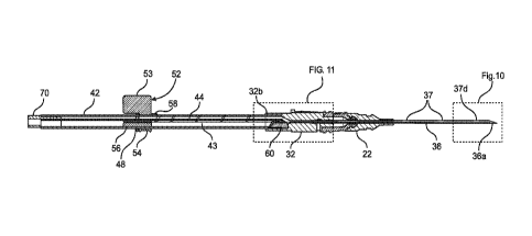
tube) during
and after wire advancement.
[0005] Rather, the blood flash in conventional catheter insertion devices
stops
during and after the subsequent wire advancement step because the wire
occupies too
much of the volume within the needle, thus reducing flow. Moreover, the wires
on
conventional devices cannot start distal to the needle flash exit location
without also
taking up too much volume and causing blood flash flow to be reduced.
Therefore, the
wires must start proximal to the blood flash exit location near the back of
the needle
and thus the first significant portion of wire advancement results in the wire
traveling
from the back of the needle (proximal to the catheter body), through the
catheter, to the
tip of the needle (distal to the catheter body) before the wire is advanced
into the vessel,
2
CA 03122585 2021-06-08
WO 2020/210488
PCT/US2020/027463
which is also known as the "dead length" for wire advancement (i.e.,
advancement that
moves the tip of the wire closer to the needle tip before the wire is advanced
out of the
needle). Such wire dead length is a common drawback in conventional devices,
as it
extends the catheterization procedure by causing a significant length of time
between
when flash is observed and when the wire is advanced into the vessel. During
this time,
continuous visible blood flash (and therefore information about the needle tip
location)
is not available in conventional devices.
[0006] Other conventional catheterization devices offer the ability for
users to
visualize blood flash during vessel puncture through a transparent, or
partially
translucent, catheter as the blood enters the small volume of space between
the inside
of the hollow catheter and the outside of the hollow needle. These devices
show flash
through the catheter when it enters into this small volume of space, but in
practice the
flash is considered once-and-done since such devices do not offer the ability
for flash
to re-start after it is first observed and very quickly fills this small
volume of space.
This aspect makes it difficult for the practitioner to recover an insertion in
which the
needle tip becomes misaligned with the vessel or passes through the vessel.
[0007] Thus, conventional catheterization devices do not permit: 1) blood
flash
visible through the catheter body, and/or 2) blood flash in the device (i.e.,
the wire tube
or the like) during and after wire advancement. Therefore, a need exists for a
novel
catheter insertion device that allows for continuous visible blood flashback
during
insertion of a catheter into the vasculature of a patient. More particularly,
there exists
a need for a catheter insertion apparatus that offers the ability to visualize
flash through
the catheter and flash in the device (i.e., the wire tube or the like) (which
also includes
the ability to re-confirm flash in wire tube or the like), and also offer the
ability to
visualize flash during and after wire guide advancement.
3
CA 03122585 2021-06-08
WO 2020/210488
PCT/US2020/027463
[0008] There is also a need for a catheter insertion apparatus that offers
the ability
to visualize flash in the wire tube or the like (which also includes the
ability to re-
confirm flash in the wire tube or the like), and also start the wire guide
inside the needle
and near the needle tip, which both reduces wire reach length and reduces wire
advancement dead length for improving ease and speed of catheterization.
[0009] Furthermore, there is a need for a catheter insertion apparatus that
offers the
ability to visualize flash in the wire advancement tube or the like (which
also includes
ability to re-confirm flash in wire tube or the like), and also separate the
wire
advancement portion of the wire tube from the blood flash chamber portion of
the wire
tube, which reduces the potential for blood exposure to occur during insertion
and for
cross-contamination between the blood from the blood flash and the external
portion of
the wire.
[0010] Additionally, a need exists for a catheter insertion device that
allows for
intuitive, easy, safe, and fast catheter placement into a patient's
vasculature.
SUMMARY
[0011] The foregoing needs are met, to a great extent, by the present
disclosure of
a catheter insertion apparatus discussed herein. The catheter insertion
apparatus
comprises a needle including a needle body connected to a needle hub, the
needle body
having a longitudinal bore and a distal needle tip configured to pierce a wall
of a blood
vessel, and the needle hub having an internal flow passage in fluid
communication with
the longitudinal bore of the needle body; a catheter configured to removably
fit over
the needle body, the catheter including a catheter body connected to a
catheter hub; a
housing including an elongated housing body is connected to the needle hub,
the
elongated housing body having an elongated lumen in fluid communication with
the
4
CA 03122585 2021-06-08
WO 2020/210488
PCT/US2020/027463
internal flow passage of the needle hub; a guide assembly slidably mounted to
the
housing body and including a guidewire having a distal guidewire tip, the
guidewire
operable to move between a retracted position in which the distal guidewire
tip is
located within the needle body and an extended position in which the distal
guidewire
tip is located outside of the needle body; and a continuous flashback chamber
is defined
by the elongated lumen of the housing body and the internal flow passage of
the needle
hub, the continuous flashback chamber configured to allow visualization of a
continuous flow of blood during insertion of the distal needle tip into the
blood vessel.
[0012] According to another aspect of the disclosure, the continuous
flashback
chamber is operable to receive the continuous flow of blood during insertion
of the
distal needle tip into the blood vessel when the guidewire is in the retracted
position,
when the guidewire is in the extended position, and during movement of the
guidewire
between the retracted and extended positions.
[0013] According to another aspect of the disclosure, a flow diverter is
configured
to divert a flow of blood from the internal flow passage of the needle hub
into the
elongated lumen of the housing body.
[0014] According to another aspect of the disclosure, the flow diverter
includes a
through-hole configured to slidably receive the guidewire.
[0015] According to another aspect of the disclosure, the flow diverter
forms a seal
with a portion of a distal end of the housing body that restricts the flow of
blood from
leaking out of the housing.
[0016] According to another aspect of the disclosure, the guide assembly
further
comprises an actuator connected to a proximal end of the guidewire, the
actuator being
movable relative to the housing and the needle to correspondingly move the
guidewire
relative to the housing and the needle between the retracted and extended
positions.
CA 03122585 2021-06-08
WO 2020/210488
PCT/US2020/027463
[0017] According to another aspect of the disclosure, the actuator includes
a collar
configured to slidably mount to the housing body.
[0018] According to another aspect of the disclosure, the actuator further
includes
a handle connected to the collar for manually sliding the collar along a
longitudinal
length of the housing body.
[0019] According to another aspect of the disclosure, the housing body
further
includes an annular band configured to abut the collar of the actuator when
the
guidewire is at its retracted position.
[0020] According to another aspect of the disclosure, the actuator further
includes
a slide member extending inwardly from the collar, the slide member having a
neck
portion and a head portion.
[0021] According to another aspect of the disclosure, the proximal end of
the
guidewire is connected to the head portion of the slide member.
[0022] According to another aspect of the disclosure, the housing body
further
comprises a longitudinal track configured to slidably receive the head portion
of the
slide member.
[0023] According to another aspect of the disclosure, the housing body
further
comprises a longitudinal slot configured to slidably receive the neck portion
of the slide
member.
[0024] According to another aspect of the disclosure, the actuator further
includes
an indicator configured to line up with corresponding indicia disposed along
the
housing body to indicate a distance of guidewire movement into the blood
vessel during
an insertion procedure.
[0025] According to another aspect of the disclosure, the housing body is
generally
tubular.
6
CA 03122585 2021-06-08
WO 2020/210488
PCT/US2020/027463
[0026] According to another aspect of the disclosure, the housing body
comprises
a substantially crescent shaped cross-section.
[0027] According to another aspect of the disclosure, the housing body and
the
needle hub comprise a transparent material or a translucent material.
[0028] According to another aspect of the disclosure, a quick flashback
chamber is
configured to allow visualization of an initial flow of blood upon insertion
of the distal
needle tip into the blood vessel.
[0029] According to another aspect of the disclosure, the quick flashback
chamber
is defined between the needle body and the catheter body, and wherein the
needle body
includes a side port to direct the initial flow of blood into the quick
flashback chamber.
[0030] According to another aspect of the disclosure, a vent plug connected
to a
proximal end of the housing body and configured to prevent blood leakage from
the
lumen of the housing body.
[0031] According to another aspect of the disclosure, the needle hub
further
comprises a safety guard configured to provide sharps protection to the distal
needle
tip.
[0032] According to another aspect of the disclosure, a catheter insertion
apparatus
comprises a needle body having a longitudinal bore and a sharp distal needle
tip
configured to puncture a wall of a blood vessel; a needle hub connected to the
needle
body, the needle hub having an internal flow passage in fluid communication
with the
longitudinal bore of the needle body; a catheter configured to removably fit
over the
needle body, the catheter including a catheter body connected to a catheter
hub; an
housing including an elongated housing body connected to the needle hub, the
elongated housing body having a lumen in fluid communication with the internal
flow
passage of the needle hub; a guidewire received within the housing body and
having a
7
CA 03122585 2021-06-08
WO 2020/210488
PCT/US2020/027463
distal guidewire tip, the guidewire operable to move between a retracted
position in
which the distal guidewire tip is located within the needle body and an
extended
position in which the distal guidewire tip is located outside of the needle
body; a
continuous flashback chamber defined by the lumen of the housing body and the
internal flow passage of the needle hub, wherein the continuous flashback
chamber is
operable to receive a continuous flow of blood before, during, and after
movement of
the guidewire between its retracted and extended positions; and a safety guard
removably received in the needle hub and configured to provide sharps
protection for
the distal needle tip.
[0033] According to another aspect of the disclosure, the elongated housing
body
further includes an elongated guidewire track configured to receive the
guidewire.
[0034] According to another aspect of the disclosure, a flow diverter is
configured
to divert a flow of blood from the internal flow passage of the needle hub
into the
elongated lumen of the housing body, and further configured to prevent blood
from
leaking into the guidewire track.
[0035] According to another aspect of the disclosure, the flow diverter
includes a
through-hole configured to slidably receive the guidewire.
[0036] According to another aspect of the disclosure, an actuator is
connected to a
proximal end of the guidewire, the actuator having a slide member having a
portion
configured to slidably mount within the track of the housing body, the
actuator operable
to move the guidewire between the retracted and extended positions.
[0037] According to another aspect of the disclosure, the housing body
comprises
a substantially crescent shaped cross-section.
[0038] According to another aspect of the disclosure, a quick flashback
chamber is
defined between the needle body and the catheter body, the quick flashback
chamber
8
CA 03122585 2021-06-08
WO 2020/210488
PCT/US2020/027463
configured to allow visualization of an initial flow of blood upon insertion
of the distal
needle tip into the blood vessel.
[0039] According to another aspect of the disclosure, the safety guard
comprises a
safety cartridge and a safety cap that cooperate with each other to define an
interior
cavity, and wherein the safety cartridge and the safety cap are configured to
slide over
the needle body toward the distal needle tip to receive the distal needle tip
within the
interior cavity.
[0040] According to another aspect of the disclosure, a pivotable latch is
located
within the interior cavity, the pivotable latch having a distal opening and a
proximal
opening both sized to allow the needle body to pass therethrough.
[0041] According to another aspect of the disclosure, a biasing member is
configured to cant the pivotable latch into locking engagement with the needle
body to
prevent removal of the distal needle tip from the interior cavity when the
needle tip is
within the cavity.
[0042] According to another aspect of the disclosure, the biasing member
comprises a spring configured to bias the pivotable latch cant about the
needle body.
[0043] There has thus been outlined certain embodiments of the disclosure
in order
that the detailed description thereof may be better understood, and in order
that the
present contribution to the art may be better appreciated. There are
additional
embodiments of the disclosure that will be described below and which form the
subject
matter of the claims appended hereto.
[0044] In this respect, before explaining at least one aspect of the
catheter insertion
apparatus in detail, it is to be understood that the catheter insertion
apparatus is not
limited in its application to the details of construction and to the
arrangements of the
components set forth in the following description or illustrated in the
drawings. The
9
CA 03122585 2021-06-08
WO 2020/210488
PCT/US2020/027463
catheter insertion apparatus is capable of aspects in addition to those
described, and of
being practiced and carried out in various ways. Also, it is to be understood
that the
phraseology and terminology employed herein, as well as the abstract, are for
the
purpose of description and should not be regarded as limiting.
[0045] As such, those skilled in the art will appreciate that the
conception upon
which this disclosure is based may readily be utilized as a basis for the
designing of
other structures, methods, and systems for carrying out the several purposes
of the
catheter insertion apparatus. It is important, therefore, that the claims be
regarded as
including such equivalent constructions insofar as they do not depart from the
spirit and
scope of the disclosure.
BRIEF DESCRIPTION OF THE DRAWINGS
[0046] In order that the disclosure may be readily understood, aspects of
the
catheter insertion apparatus are illustrated by way of examples in the
accompanying
drawings, in which like parts are referred to with like reference numerals
throughout.
[0047] FIG. 1 is a perspective view of a catheter insertion apparatus
according to
an implementation of the present disclosure.
[0048] FIG. 2 is a side elevation view of the catheter insertion apparatus
of FIG. 1.
[0049] FIG. 3 is a top plan view of the catheter insertion apparatus of
FIG. 1.
[0050] FIG. 4A is a cross-sectional side elevation view of a guide assembly
of the
catheter insertion apparatus of the present disclosure.
[0051] FIG. 4B is a cross-sectional side elevation view of an housing
assembly of
the catheter insertion apparatus of the present disclosure.
[0052] FIG. 4C is a cross-sectional side elevation view of a needle
assembly of the
catheter insertion apparatus of the present disclosure.
CA 03122585 2021-06-08
WO 2020/210488
PCT/US2020/027463
[0053] FIG. 4D is a cross-sectional side elevation view of a catheter of
the catheter
insertion apparatus of the present disclosure.
[0054] FIG. 5A is a cross-sectional side elevation view of the catheter
insertion
apparatus in a retracted position as taken along lines 5A-5A of FIG. 3.
[0055] FIG. 5B is a cross-sectional side elevation view of the catheter
insertion
apparatus of FIG. 5A in an extended position
[0056] FIG. 6 is an enlarged side elevation view of an actuator of the
catheter
insertion apparatus of the present disclosure.
[0057] FIG. 7 is a front cross-sectional view of the actuator taken along
lines 7-7
of FIG. 6.
[0058] FIG. 8A is a front perspective view of a flow diverter of the
catheter
insertion apparatus of the present disclosure.
[0059] FIG. 8B is a rear perspective view of the flow diverter shown in
FIG. 8A.
[0060] FIG. 9 is a top plan view of a portion of the catheter insertion
apparatus of
the present disclosure.
[0061] FIG. 10 is an enlarged cross-sectional side elevation view of the
portion of
the catheter insertion apparatus demarcated in FIG. 5A showing a distal end of
the
catheter insertion apparatus of the present disclosure.
[0062] FIG. 11 is an enlarged cross-sectional side elevation view of the
portion of
the catheter insertion apparatus demarcated in FIG. 5A showing the proximal
end of
the needle assembly and the distal end of the housing.
[0063] FIG. 12A is an enlarged top plan view of an implementation of a
distal
needle tip of the present disclosure.
[0064] FIG. 12B is an enlarged top plan view of another implementation of a
distal
needle tip of the present disclosure.
11
CA 03122585 2021-06-08
WO 2020/210488
PCT/US2020/027463
[0065] FIG. 13A is a top perspective view of an implementation of a blood
containment and vent plug of the present disclosure.
[0066] FIG. 13B is a bottom perspective view of the blood containment and
vent
plug of FIG. 13A.
[0067] FIG. 13C is a top perspective view of another implementation of a
blood
containment and vent plug of the present disclosure.
[0068] FIG. 14 is a cross-sectional side elevation view of a catheter
insertion
apparatus having a needle guard according to another implementation of the
present
disclosure.
[0069] FIG. 15A is an enlarged cross-sectional side elevation view of the
needle
guard of FIG. 14 in an unlocked position.
[0070] FIG. 15B is an enlarged cross-sectional side elevation view of the
needle
guard of FIG. 14 in a locked position.
DETAILED DESCRIPTION
[0071] As will be discussed in detail herein, the present disclosure
describes an
integrated over-the-needle catheter insertion apparatus operable to provide
continuous
blood flash visibility during catheterization. The catheter insertion
apparatus is
operable to provide continuous blood flash visibility (i.e. flash through a
catheter, flash
in a wire tube, ability to re-confirm flash in the wire tube, and ability to
see flash in the
wire tube both during and after wire guide advancement). The catheter
insertion
apparatus is also operable to provide the continuous blood flash visibility
while starting
the wire guide tip inside and near the needle tip, without causing excessive
blood
exposure, and without impacting other critical aspects of an insertion
procedure. The
catheter insertion device of the present disclosure therefore improves
insertion success
12
CA 03122585 2021-06-08
WO 2020/210488
PCT/US2020/027463
rates and increases the confidence of practitioners in knowing that the needle
tip is
located inside the vessel throughout the entire insertion procedure without
causing
excessive blood exposure. The present catheter insertion apparatus may be
utilized for
catheterization of various vessels, including the radial artery or other
arterial vessels, as
well as the venous vasculature. Further, the present catheter insertion
apparatus may be
utilized to insert an introducer catheter used for facilitating the insertion
of other
catheters, such as a PICC (Peripherally Inserted Central Venous Catheter) or
CVC
(Central Venous Catheter) or other vascular access devices.
[0072] FIGS. 1-3 illustrate a catheter insertion apparatus 10 according to
an
implementation of the present disclosure. The catheter insertion apparatus 10
comprises an over-the-needle catheter 20, a needle 30, a housing 40, and a
movable
integrated guide assembly 50. The catheter insertion apparatus 10 is
configured to
provide continuous blood flash visibility during catheterization, including
before
moving the guide assembly 50, during movement of the guide assembly, and after
movement of the guide assembly.
[0073] The catheter 20 includes a distal catheter end 20a and a proximal
catheter
end 20b. The needle 30 likewise includes a distal needle end 30a and a
proximal needle
end 30b. The proximal end 20b of the catheter 20 is configured to fit over the
distal
end 30a of the needle 30 when assembled together. The catheter 20 and the
needle 30
cooperate to form a first or quick blood flashback chamber 24, as will be
described in
further detail below. The housing 40, or wire tube, comprises an elongated
generally
tubular body 42 having a distal housing end 42a and a proximal housing end
42b. The
housing body 42 includes a longitudinal groove or channel that defines an
elongated
guidewire track 43 configured to cooperate with the guide assembly 50. The
guidewire
track 43 extends from the distal housing end 42a to the proximal housing end
42b of
13
CA 03122585 2021-06-08
WO 2020/210488
PCT/US2020/027463
the housing body 42. The housing body 42 also includes a longitudinal lumen 44
that
cooperates with a needle hub 32 of the needle 30 to define a second or
continuous blood
flashback chamber. The guidewire track 43 and the portion of the second
flashback
chamber extending from the distal end 42a to the proximal end 42b of the
housing body
42 may further extend substantially parallel to one another.
[0074] The distal end 42a of the housing body 42 is secured to the proximal
end
30b of the needle 30. In some instances, the needle assembly 30 may be
removably
connected to the housing 40. In other instances, the needle assembly 30 may be
integral
with the housing 40. The distal end 42a of the housing body 42 is connected to
a flow
diverter 60 configured to provide a visible continuous or uninterrupted blood
flash
within the second flashback chamber by directing blood into the second
flashback
chamber and away from the guidewire track 43. The proximal end 42b of the
housing
body 42 is sealed by a removable blood containment and vent plug 70, as will
be
described in further detail below. The guide assembly 50 comprises an actuator
52,
such as a slider, connected to a proximal end 59b of a guidewire 59. The guide
assembly 50 is configured to move along a longitudinal length of the housing
40 by
correspondingly sliding the actuator 52.
[0075] Referring to FIGS. 4A-4D, each of the aforementioned components of
the
catheter insertion apparatus 10 are separately shown prior to assembly for
illustration
purposes. In particular, FIG. 4A depicts the guide assembly 50 comprising the
guidewire 59 and its actuator 52. FIG. 4B shows the body 42 of the housing 40
which
receives the guidewire 59 and slidably carries its actuator 52. The housing
body 42 is
connected to the needle 30 shown in FIG. 4C, where the needle 30 includes a
needle
hub 32 and a hollow needle body 36. The needle 30 carries the over-the-needle
catheter
14
CA 03122585 2021-06-08
WO 2020/210488
PCT/US2020/027463
20 as shown in FIG. 4D, where the catheter 20 includes a catheter hub 22 and a
catheter
body 26.
[0076] In FIG. 5A, a cross-sectional view of the catheter insertion
apparatus 10 is
shown in its assembled state prior to use, in which the housing 40 removably
carries
the catheter 20 on the needle 30 in an over-the-needle position, and where the
guide
assembly 50 is in its normal retracted position. In this retracted position,
the distal end
59a of the guidewire 59 is located within the needle body 36. The needle 30 is
of a
length in relation to the catheter 20 such that when the catheter 20 is
secured on the
needle 30, the distal end 30a of the needle assembly 30 extends beyond the
distal end
20a of the catheter 20.
[0077] FIG. 5B depicts a cross-sectional view the catheter insertion
apparatus 10
during a catheterization procedure in which the guide assembly 50 is in its
fully
extended position for guiding the insertion of the catheter body 26 into a
blood vessel.
The needle 30 is connected to the housing body 42, which body 42 also carries
the
actuator 52 of the guide assembly 50. The actuator 52 is shown moved along the
length
of the housing body 42 to distally advance the guidewire 59 from its normal
retracted
position to an extended position. The actuating handle or wing 53 is located
such that
it may be manipulated by a thumb of the user placing the catheter body 26 into
the
blood vessel while the housing 40 and/or the needle 30 is grasped to
facilitate either
one handed or two handed operation of the apparatus 10. Further, a flexible
portion of
the catheter 20 allows the catheter to be bent at large angles without
kinking, i.e., after
insertion in the vasculature. Also, an auxiliary device, such as a valve or
tubing, may
be connected to the catheter hub 22 after insertion into the vasculature.
[0078] Turning back to FIG. 4A, a distal end 59a of the guidewire 59
includes a
rounded tip, such as a semi-spherically shaped tip, for minimizing or
preventing injury
CA 03122585 2021-06-08
WO 2020/210488
PCT/US2020/027463
to a blood vessel during insertion. The proximal end 59b of the guidewire 59
is securely
attached to the actuator 52. The actuator 52 includes a cylindrical collar 54
configured
to slide over the tubular body 42 of the housing 40. A handle or wing 53 is
connected
to the collar 54 for moving the actuator 52 and guidewire 59 along the length
of the
housing body 42. The handle 53 may be ergonomically shaped, and may further
comprise an anti-slip surface, such as ridges or bumps, to provide a non-slip
grip. A
slide member 55 is also connected to the cylindrical collar 54 and configured
to slide
within the longitudinal groove 43 of the housing body 42.
[0079] With reference to FIGS. 6 and 7, the relationship between the
actuator 52
and the housing body 42 is depicted. In particular, the housing body 42
includes a
generally round outer wall 45 configured to cooperate with the cylindrical
collar 54,
and a generally oblong inner wall or dividing wall 46 that forms the
longitudinal groove
43 and is configured to slidably receive the slide member 55. The outer wall
45 and
the inner wall 46 further form the longitudinally extending lumen 44 that
cooperates
with the needle hub 32 to define the second flashback chamber. Further, the
contiguous
portions of the outer and inner walls 45, 46 form a longitudinal slot 47
extending
parallel to and alongside the longitudinal guidewire track 43. In some
instances, the
lumen 44 may comprise a substantially crescent-shaped cross-section defined by
the
outer and inner walls 45, 46. Both the outer wall 45 and the inner wall 46 may
be
transparent or translucent so that blood flash within the flashback chamber is
readily
visible. Centrally in the housing body 42, the inner wall or divider wall 46
is shaped to
provide the longitudinally extending medial track 43 to receive a bulbous head
56 of
the slide member 55. Further, a slot 47 coextensive with the track 43 and
defining an
opening to the track is provided in the outer wall 45 of the body 42. The slot
47 is in
communication with the track 43, and is also configured to receive a neck 57
of the
16
CA 03122585 2021-06-08
WO 2020/210488
PCT/US2020/027463
slide member 55 to secure the actuator to the housing body and prevent the
actuator
from rotating about the housing.
[0080] Turning back to FIGS. 4B and 4C the housing body 42 has a distal end
42a
and a proximal end 42b. The lumen 44 and the guidewire track 43 are open
through
the proximal end 42b of the housing body 42. An open end of the lumen 44 at
the distal
end 42a of the housing body 42 cooperates with an internal flow passage of the
needle
hub 32 to form the continuous flashback chamber. The proximal end 42b of the
lumen
44 of the housing body 42 is closed against blood flow by a porous blood
containment
and vent plug 70 that is configured to enable the purging of air.
[0081] As previously described, the needle 30 has a distal end 30a and a
proximal
end 30b, and comprises a needle hub 32 and a needle body 36. The needle hub 32
has
a distal end 32a and a proximal end 32b, and the needle body 36 has a sharp
beveled
distal tip 36a and a proximal end 36b. The needle hub 32 may be transparent or
translucent to allow visualization of blood therein. Further, the needle hub
32 includes
a flow passage extending therethrough and defining a narrow portion 33 and a
countersink portion 34. An internal cavity 35 is provided at the proximal end
32b of
the needle hub and is configured to receive a portion of the distal end 42a of
the housing
body 42. The countersink portion 34 of the flow passage is disposed between
the fluid
narrow portion 33 and the internal cavity 35.
[0082] The needle body 36 has an internal needle lumen or bore 36c
extending from
its distal tip 36a to its proximal end 36b. The needle body includes at least
one side
port 37 configured to allow a flow of blood into the quick blood flashback
chamber 24.
The proximal end 36b of the needle body 36 is fixedly secured to the distal
end 32a of
the needle hub 32 so that the internal needle bore 36c is in fluid
communication with
the internal flow passage, including the narrow and countersink portions 33,
34.
17
CA 03122585 2021-06-08
WO 2020/210488
PCT/US2020/027463
Further, the internal flow passage of the needle hub cooperate with the lumen
44 of the
housing body 42 to define the continuous blood flashback chamber. The needle
hub 32
may further include a grip member 39, such as a protruding rib, to assist a
user in
gripping the needle assembly 30 during an insertion procedure.
[0083] FIG. 4D shows the catheter 20, which has a distal end 20a and a
proximal
end 20b. The catheter assembly 20 also includes a catheter hub 22 and a
catheter body
26, the catheter body 26 having a distal tip 26a and a proximal end 26b. The
catheter
body 26 further includes an internal lumen or bore 26c extending from the
distal tip 26a
to the proximal end 26b. When the catheter insertion 10 apparatus is
assembled, the
distal end 42a of the housing body 42 is securely received within the proximal
end 32b
of the needle hub 32, and the catheter 20 is fit over the needle body 36 of
the needle
assembly 30. The elongated lumen 44 of the of the housing 40 is in fluid
communication with the needle bore 36c via fluid communication with the
internal flow
passage of the needle hub 32. The distal tip 26a of the catheter body 26 may
include a
progressively decreasing cross-section or taper to facilitate insertion into
the blood
vessel. Further, the catheter body 26 is supported at its proximal end 26b by
the catheter
hub 22 which may comprise laterally projecting suture wings (not shown) in
some
implementations, although it should be understood that the catheter hub 22 may
be
provided with other means for retention of the catheter assembly 20 on the
patient after
placement in the blood vessel.
[0084] Disposed within the distal end 42a of the housing body 42 and within
the
proximal end 32b of the needle hub 32 closing off the distal end 42a of the
guidewire
track 43 is a flow diverter 60 having a distal end 60a and a proximal end 60b.
As shown
in FIGS. 8A and 8B, the distal end 60a of the flow diverter includes a slanted
surface
62 configured to divert a flow of fluid from the internal passage of the
needle into the
18
CA 03122585 2021-06-08
WO 2020/210488
PCT/US2020/027463
lumen 44 of the housing assembly 40. The flow diverter 60 further comprises a
passage
or through-hole 64 configured to allow the guidewire 59 to slidably pass
therethrough
without interrupting fluid communication between the needle bore 36c and the
lumen
44. As a result, a blood flashback into the second flashback chamber is
continuous
irrespective of the movement of the guidewire along the length of the housing
and the
needle.
[0085] In particular, the passage 64 is formed by a guidewire receiving
opening
extending from distal end 60a to the proximal end 60b, and through which the
guidewire
59 is passed for longitudinal movement relative to the housing 40. The fit
between the
guidewire 59, which may have a uniform diameter, and the passage 64 is such as
not to
interfere with easy sliding movement of the guidewire 59, and at the same
time, to
prevent or minimize a flow of blood therethrough and into the guidewire track
43. This
is accomplished because the proximal end 60b of the flow diverter 60 is
configured to
snugly fit within the guidewire track 43 at the distal end 42a of the housing
body 42,
and thus the track 43 is closed at the distal end 42a of the housing body 42.
[0086] The guidewire track 43 remains open at the proximal end 42a of the
body
42 and along its bottom surface via the coextensive slot 47 longitudinally
extending and
medially disposed in the outer wall 45 of the housing body 42. The distal
surface 60a
of the diverter 60 therefore diverts the flow of flashback blood into the
adjoining lumen
portion 44 of the continuous flashback chamber at the distal end 42a of the
housing
body 42. The flow diverter restricts a flow of blood from entering the
guidewire track
43, such that any blood leakage through the diverter passage 64 and into the
guidewire
track 43 would be minimal. Furthermore, other configurations of the diverter
may
include a silicon seal that creates a tight seal around the wire, and a duck-
bill seal that
accomplishes a similar liquid tight seal.
19
CA 03122585 2021-06-08
WO 2020/210488
PCT/US2020/027463
[0087] In some implementations, the continuous flashback chamber may be
used
for a catheter insertion procedure into the venous system as well as into the
arterial
system. The venous system has a lower pressure which causes a slower flow
rate.
Additionally, there is no observable pulsatile blood return in the venous
system as is in
the artery. This provides an increased difficulty in observing blood flowing
as it's much
harder to see a slow blood return from the quick pulsatile blood return. To
compensate
for this, the continuous flashback chamber may have a smaller cross-sectional
area so
that the flow of blood can still be observed. In some aspects, the continuous
flashback
chamber may be helical or spiral shaped, or other significantly curved shape,
to
compensate for a smaller volume of blood flow therein.
[0088] In another implementation, the continuous flashback chamber may
comprise a plurality of vertical cavities disposed within the interior of the
chamber. For
instance, each cavity may be spaced apart approximately every 2mm. When the
blood
flow reaches a vertical cavity, it wicks upward and fills the empty space
which is easily
observable to the practitioner. The practitioner is therefore able to observe
blood
continuously wicking upward into the subsequent vertical cavities within the
lumen. In
another implementation, several separate pieces of a gauze or paper-like
material may
be disposed within the vertical cavities in order to quickly soak up blood
along the
length of the flash chamber to further improve the wicking ability.
[0089] Referring again to FIG. 4C, the needle 30 includes an elongated
needle body
36 of a gauge generally in the range of 16-24. The needle body 36 is mounted
at its
proximal end 36b on the needle hub 32 and has a beveled distal tip 36a. The
needle
hub 32 has a proximal end 32b and a distal and 32a. The distal end 32a of the
needle
hub 32 comprises a male luer connector, such as a male luer slip tip 38,
configured and
sized for a fluid tight, yet releasable, connection to a corresponding female
luer
CA 03122585 2021-06-08
WO 2020/210488
PCT/US2020/027463
connector 28 provided at the proximal end 20b of the catheter hub 22. The
proximal
end 32b of the needle hub body 32 is sized and configured to receive a portion
of the
distal end 42a of the housing body 42.
[0090] The needle body 36 includes a needle bore 36c of uniform cross-
section
which receives the guidewire 59 with suitable clearance, and the beveled
distal tip 36a
of the needle body 36 is orientated upward. A flashback blood port 37 is
provided on
an uppermost surface of the needle body 36. In some instances, a plurality of
blood
ports 37 may be provided along the uppermost surface of the needle body 36.
For
instance, the ports 37 may be arranged in spaced relation with each other
along a length
of the needle body 36. The blood ports 37 provide an opening for the entrance
of blood
into the quick flashback chamber 24. More specifically, the ports 37 in the
needle body
36 are spaced proximally of the beveled distal tip 36a to provide an
intermediate section
of the elongated needle body 36 which is configured to cooperate with the
elongated
catheter body 26 to define the quick flashback chamber 24 located between the
outside
wall of the needle body 36 and the inside wall of the catheter body 26.
[0091] During catheterization, the guidewire actuator 52 is used for moving
the
guidewire 59 within the guidewire track 43 of the housing body 42 through a
stroke
spanning a length of the track. Such movement of the actuator 52 distally
along the
housing body 42 toward the needle 30, as shown in FIG. 5B, results in the
rounded or
spherical distal tip 59a of the guidewire 59 projecting beyond the distal tip
36a of the
needle assembly 30 and into the blood vessel so that the guidewire 59 can
guide the
catheter into a desired placement within the blood vessel. The guidewire
actuator 52
includes an upstanding actuating handle or wing 53 which projects away from
the
housing body 42 and is in a readily accessible position for the user. The
cylindrical
21
CA 03122585 2021-06-08
WO 2020/210488
PCT/US2020/027463
collar 54 of the actuator is operable to slide along the outer wall 45 of the
housing body
42. The slide member 55 projects inwardly from the collar 54.
[0092] As previously mentioned, the slide member 55 includes the bulbous
head 56
and the neck 57 which slidably fit in the guidewire track 43 and the slot 47,
respectively.
The head 56 and the neck 57 of the actuator 52 are thus operable to prevent
rotation of
the actuator about the housing body 42. Further, the bulbous head 56 is
attached to the
proximal end 59a of the guidewire 59 for advancing and retracting the
guidewire in
response to movement of the actuator 52 between its limit positions.
[0093] The actuator 52 may also include an indicator 58 connected to the
collar 54
and configured to line up with indicia 49 disposed along the length of the
housing body
42 in order to indicate a distance that the guidewire 59 has moved relative to
housing
body 42 and into the blood vessel during an insertion procedure. As shown in
FIG. 9,
the indicator 58 and indicia 49 may be correspondingly shaped. For instance,
the
indicator 58 and indicia 49 may have a chevron shape. The indicia 49 may
further
include spaced apart alphanumeric markings 49a to indicate a specific distance
of
guidewire advancement along the housing body 42. For instance, such markings
may
be spaced every centimeter from a home position 49b (i.e., to allow for 3.5 cm
of
guidewire advancement along a 4 cm catheter).
[0094] Further, the home position 49b may have an arrow shaped marking to
help
confirm that the guidewire is not advanced during vessel puncture. The distal
tip 59a
of the guidewire 59 is positioned at the heel of the needle bevel when the
indicator 58
reaches a first mark (i.e., a "0" mark) during guidewire advancement. Further,
the
housing body 42 may include an annular band 48 having a larger diameter than
the
outer diameter of the body 42 to act as a bump against which the collar 54 of
the actuator
52 is configured to abut and pass over when the guide assembly 50 is
proximally
22
CA 03122585 2021-06-08
WO 2020/210488
PCT/US2020/027463
retracted from a distally extended position. For instance, the resistance
created between
the annular band 48 and the collar 54 makes it difficult, but possible, for a
user to retract
the actuator 52 past the annular band 48.
[0095] Referring again to FIG. 5A, at the start of a catheterization
procedure, the
actuator 52 is disposed in the fully retracted position. In this fully
retracted position,
the rounded distal tip 59a of the guidewire 59 may be located proximal of the
distal tip
36a of the needle assembly 30 and in a clearance position with respect to the
most distal
needle port 37d so as not to inhibit an early visualization of blood flashback
into a space
between the needle body 36 and the catheter body 26. Upon movement of the
actuator
52 from its initial retracted position toward its fully extended position,
i.e., toward the
distal end 42a of the housing body 42 as shown in FIG. 5B, the indicator 58
will contact
and abut the proximal end 32b of the needle hub 32. Such contact limits
further
movement of the actuator 52 as well as the corresponding amount of extension
of the
distal tip 59a of the guidewire 59 past the distal tip 36a of the needle and
into the blood
vessel.
[0096] An annular space formed between the needle body 36 and the catheter
body
26 defines the quick blood flashback chamber 24. Stated another way, the quick
blood
flashback chamber 24 has an annular cross-section and is disposed between the
catheter
body 26 and the needle body 36 when catheter assembly 20 is carried on the
needle
assembly 30 in the over-the-needle position. With particular reference to FIG.
10, the
internal bore 26c of the catheter body 26 forms a relatively shallow
longitudinally
extending well or recess 26d with the needle body 36, where the distal portion
26e of
the well 26d is located distally of the distal-most flashback port 37d, and
where the
proximal end of the well is located proximally of the proximal-most flashback
port
provided in the uppermost surface of the needle body 36.
23
CA 03122585 2021-06-08
WO 2020/210488
PCT/US2020/027463
[0097] The interior wall of the catheter body 26 and the exterior wall of
the needle
body 36 form a snug fit that may be fluid tight between the distal portion 26e
of the
well 26d and the distal end 26a of the catheter body 26. Thus, no fluid
leakage will
occur between the distal end of the quick flashback chamber 24 and the tip 36a
of the
needle body 36 when blood flows from a vessel through the needle bore 36c and
into
the first flashback chamber 24 through ports 37. The catheter hub 22 and the
needle
hub 32 similarly form a snug fit at the proximal end of the annular quick
flashback
chamber 24 to prevent any leakage of blood. It should be appreciated that air
may
escape into the atmosphere through the proximal end of the annular quick
flashback
chamber 24 and between the male slip 38 of the needle assembly 30 and the
corresponding female luer connector 28 of the catheter 20 in order to permit
blood flow
into the quick flashback chamber.
[0098] Further, in some instances, the spacing of the distal-most port 37d
from the
distal needle tip 36a may be such that only a relatively short path for blood
flow exists
from the beveled distal tip 36a of the needle body 36 through the needle bore
36c and
into the distal-most flashback port 37d. Moreover, as shown in FIG. 10, when
the
guidewire 59 is in the retracted position, its spherical distal tip 59a may be
disposed in
a non-obstructing or clearance position in relation to the most distal or
first blood
flashback port 37d encountered by the initial blood flow into the needle bore
36c. In
particular, the distal tip 59a of the guidewire 59 is shown substantially
intermediate the
distal and proximal ends of the first flashback port 37d, which provides an
unobstructed
flow path to the first flashback port 37d, and thus the guidewire does not
interfere with
entry of blood into the first flashback chamber 24. In some aspects, the
rounded distal
tip 59a may divert a flow of blood into the port 37d. It should be appreciated
that other
24
CA 03122585 2021-06-08
WO 2020/210488
PCT/US2020/027463
non-obstructing positions may be established for the guidewire 59 in relation
to the first
flashback port 37d.
[0099] Visualization of the blood flash will occur throughout the length of
the first
flashback chamber 24 due to the at least one flashback port 37 provided on the
needle
body 36. Moreover, the diameter of the guidewire 59 may be selected in
relation to the
diameter of the needle bore 36c to provide an annular blood flow passage 36d
therebetween which communicates with the first flashback chamber 24 through
the
spaced ports 37. Thus, when the guidewire 59 is in the retracted position as
shown in
FIG. 10, two flow paths are established for flashback blood. Specifically, a
first flow
path through the multiple flashback ports 37 and into the first flashback
chamber 24,
and a second flow path via the annular blood flow passage 36d extending along
the
longitudinal extent of the guidewire 59 from its distal tip 59a, into the
second flashback
chamber defined by the internal flow passage of the needle hub 32 and the
lumen 44 of
the housing body 42.
[0100] Thus, blood flash is permitted because the outer diameter of the
guidewire
is small enough to allow enough flash back between the outer diameter of the
guidewire
and the inner diameter of the needle. In other implementations, the blood
flash may be
permitted due to other design features, including cutting grooves and/or slots
formed
into the inner surface of the needle that allow for an increased volume of
blood to flow
between the inner diameter of the needle and the outer diameter of the
guidewire.
Similarly, cutting grooves and/or slots may be formed on the outer diameter of
the
guidewire to allow for an increased volume of blood to flow through the space
between
the inner diameter of the needle and the outer diameter of the guidewire.
Further, the
cross sectional area of the guidewire may be varied with different patterns
that add
volume when the blood passes. Such varying patterns may be configured to
maintain
CA 03122585 2021-06-08
WO 2020/210488
PCT/US2020/027463
the desired rigidity necessary for guidewire wire advancement over the needle.
For
example, if the wire is flat pressed it has more rigidity in the vertical
direction
[0101] Referring now to FIG. 11, the needle hub body 32 includes an
internal flow
passage having a narrow portion 33 which, at its distal end, communicates with
the
needle bore 36c and, at its proximal end, communicates with the countersink
portion
34 of the internal flow passage. The countersink 34 in turn communicates with
the
lumen 44 of the housing 42 which has a distal end 42a provided within an
internal
cavity 35 formed at the proximal end 32b of the needle hub 32. The internal
flow
passage of the needle hub 32 cooperates with the longitudinal lumen 44 of the
housing
body 42 to define the continuous blood flashback chamber. More particularly,
blood
flow from the needle bore 36c through the narrow portion 33 and the
countersink
portion 34 of the internal flow passage is diverted into the distal end 42a of
the
longitudinal lumen 44 of the housing body 42 via the slanted surface 62 of the
flow
diverter 60. The through-hole 64 of the diverter is configured to permit
longitudinal
movement of the guidewire 59 without blocking or interrupting the blood flow
path
into the lumen 44, and thus providing the visible continuous flow of blood
during an
insertion procedure.
[0102] Thus, when the hub 32 of the needle assembly 30 is mounted on the
distal
end of the housing body 42 and fixedly attached thereto, for example, by use
of an
appropriate adhesive or the like, a continuous path for flashback blood is
established
from the beveled tip 36a of the needle body 36 through an internal flow
passage of the
needle hub 32 and into the lumen 44 of the housing via the slanted surface 62
of the
flow diverter 60. The needle hub 32 may also include a grip member 39 between
the
distal and proximal ends 32a, 32b of the needle hub. The grip member 39 is
configured
to assist a user in grasping the needle assembly during the catheterization
procedure.
26
CA 03122585 2021-06-08
WO 2020/210488
PCT/US2020/027463
The grip member 39 may include radially extending ribs circumferentially
spaced apart
at their outermost edges to assist the user with gripping the needle hub.
[0103] As previously described, both the needle hub 32 and the housing body
42
may be transparent or translucent to allow visualization of the continuous
blood flash
within the second blood flashback chamber. For instance, the needle hub 32 may
be
formed from a moldable thermoplastic material. The housing body 42 may be
formed
of a transparent or translucent, semi-rigid plastic material having some
flexibility with
sufficient resilience so that it maintains its generally tubular configuration
during use.
The needle body 36 may be formed of an appropriate metal, such as stainless
steel. The
blood ports 37 provided for visualization of flashback blood into the first
flashback
chamber 24 may be ground into the upper surface of the needle body 36. The
guidewire
59 may be a spring wire fabricated of metal, such as stainless steel or
nitinol. The
elongated catheter body 26 may similarly be clear or translucent to provide
for
visualization of blood flash in the first flashback chamber 24. For instance,
the catheter
body 26 may be manufactured from a single lumen catheter blank of transparent
or
translucent polyurethane. In some implementations, the catheter insertion
apparatus
may further comprise a protective cover configured to fit over the catheter
body 26
when the catheter 20 is fit over the needle body 36 of the needle assembly 30.
[0104] Thus, during a catheterization procedure, the user first punctures
the blood
vessel with the needle tip 36a of the catheter insertion apparatus 10, in
which the guide
assembly 50 is in its retracted position, by using a continuous and controlled
forward
movement so as to avoid transfixing the vessel walls. The user will know
whether a
successful entry of the needle tip 36a into the blood vessel was achieved when
an
immediate appearance of flash blood into the first or quick flashback chamber
24 is
27
CA 03122585 2021-06-08
WO 2020/210488
PCT/US2020/027463
visible, which is followed by visualization of blood flash within the second
or
continuous flashback chamber.
[0105] Once the user has confirmed the desired position of the needle tip
36a into
the blood vessel, the needle assembly 30 is stabilized and distal advancement
of the
guidewire 59 via the actuator 52 is carefully performed by moving through a
relatively
short forward stroke. As the guidewire 59 is distally advanced, the second
flashback
chamber receives a continuous flow of blood which lets the user know that the
desired
needle placement is maintained. If the user retracts the guidewire 59 while
the needle
tip is still in the blood vessel due to resistance encountered while advancing
the
guidewire, the second flashback chamber will nevertheless still receive a
continuous
flow of blood as long as placement of the needle tip is maintained within the
blood
vessel.
[0106] Once the guidewire 59 is located within the blood vessel for a
length
predetermined by the performed stroke of the actuator 52, the user grips the
catheter
body 22 and advances the catheter 20 distally relative to the needle assembly
30. The
distal end 20a of the catheter 20 is configured to track the position of the
guidewire 59
into the blood vessel. Thereafter, while holding the catheter 20 in place
within the
vessel, the user may remove the needle assembly 30 from the vessel. An
auxiliary
device, such as an injection cap, a valve, or a medical tubing may then be
attached to
the luer connector 28 of the catheter hub 22.
[0107] The distal needle tip 36a may further comprise one or more echogenic
features, in addition to the sharp tip, as depicted in FIGS. 12A and 12B. Such
echogenic
features may include, for example, a divot 36e as shown in FIG. 12A. Such a
divot 36e
is operable to improve the echogenicity of the needle tip 36a when observed
under
ultrasound. Similarly, such echogenic features may also include, for example,
a
28
CA 03122585 2021-06-08
WO 2020/210488
PCT/US2020/027463
through-hole 36f as shown in FIG. 12B. Such a through-hole 36e is also
operable to
improve the echogenicity of the needle tip 36a when observed under ultrasound.
The
visible echogenic features enable a practitioner to better visualize the
location of the
needle body 36 when using ultrasound imaging equipment.
[0108] As previously described, the lumen 44 and the guidewire track 43 are
open
through the proximal end 42b of the housing body 42. This open proximal end
42b of
the lumen 44 of the housing body 42 is sealed by the porous blood containment
and
vent plug 70 that is configured to enable the purging of air from within the
lumen while
also preventing blood flow from leaking out of the proximal end 42b of the
lumen 44.
Further, the plug 70 is configured to not seal the proximal end of the
guidewire track
43.
[0109] In particular, as shown in FIGS. 13A and 13B, an implementation of
the
plug 70 includes a plug body 72 configured to fit within the lumen 44 at the
proximal
end 42b of the housing body 42. The plug 70 further includes an enlarged plug
head
configured to abut the proximal end 42b of the housing body when the plug body
72 is
inserted into the lumen 44. A longitudinal channel 75 extends through the
length of the
plug 70 and is configured to ensure that the guidewire track 43 is not plugged
when the
plug body 72 is inserted into the lumen 44. The plug body 72 and the plug head
74
therefore both may have a substantially crescent shaped cross-section
corresponding to
the substantially crescent shaped cross-section of the lumen 44. In another
implementation, the plug 70 may further include at least one longitudinal and
cylindrical vent extending through the length of the plug and operable allow
the purging
of air from within the lumen while also preventing blood flow from leaking out
of the
proximal end 42b of the lumen 44.
29
CA 03122585 2021-06-08
WO 2020/210488
PCT/US2020/027463
[0110] FIG. 13C illustrates another implementation of the plug 70a
including at
least one ventilation through hole 76 configured to be in direct communication
with the
lumen of the housing body. In other implementations, the plug may include a
crescent
shaped hole configured to mate with the crescent shape of the lumen of the
housing,
and an extruded or raised surface configured to mate with the guidewire track.
Other
implementations may include a bloodless plug formed integrally with the
housing body.
Yet other implementations may comprise a bloodless plug including a small
silicon
sheet that is pre-slit so that the guidewire is operable to be pushed through
the slit,
wherein the slit is operable to seal around the outer diameter of the
guidewire. In yet
other implementations, a duck-bill shaped silicon seal may be operable to
allow the
guidewire to be pushed therethrough, but when pressure from vasculature is
exerted on
the outside of the seal, it closes itself over the guidewire thus preventing
blood leakage.
[0111] Other implementations may include a second chamber configured to
contain
blood droplets that may escape through the small clearance between the plug
hole and
the outer diameter of the guidewire. This blood containment area may be an
empty
space that allows for blood collection. The blood containment area may
alternatively
contain gauze or other absorbent material that further keeps blood that
escaped from
dripping out of the chamber. Other implementations may include a wire advancer
operable to mate with the bloodless plug so that when the wire advancer is
fully
advanced, the bloodless plug hole is further blocked to prevent blood seepage.
[0112] FIG. 14 illustrates a catheter insertion apparatus 100 configured to
provide
continuous blood flash visibility during catheterization according to another
implementation of the present disclosure. The catheter insertion apparatus 100
is
similar to the catheter insertion apparatus 10 previously described above,
except the
catheter insertion apparatus 100 comprises a needle assembly 130 operable to
provide
CA 03122585 2021-06-08
WO 2020/210488
PCT/US2020/027463
sharps protection for the distal needle tip 136a. More particularly, the
needle assembly
130 comprises a needle hub 132 configured to removably receive a safety guard
210
operable to provide sharps protection for the distal needle tip 136a.
[0113] FIG. 15A shows the safety guard 210 is removably provided within the
distal end 132a of the needle hub 132. The safety guard 210 includes a
generally hollow
safety cartridge 212 that is formed with a proximal opening 214 at a proximal
end
thereof The safety guard 210 further includes a safety cap 216 having a
through hole
218 configured to slidably receive the needle body 136. The safety cap is 216
configured to releasably secure to the catheter 20. In particular, the safety
cap 216
includes a tip 217 at its distal end having a pair of clips that are
configured to expand
when the needle is passed through the tip 217. When the clips are expanded,
they mate
with a corresponding inner ring disposed on an interior surface of the
catheter hub for
preventing the safety assembly from being easily removed from the catheter.
[0114] The safety cartridge 212 and the safety cap 216 are preferably
molded from
a plastic material. The safety cap 216 may be secured to the safety cartridge
212 by tab
members extending from the cap and configured to securely snap into respective
detents
formed in the cartridge. In other implementations, the safety cap may be
secured to the
safety cartridge with a glue, a solvent, or some other adhesive. Once secured
together,
the cartridge 212 and the cap 216 cooperate to define an interior cavity 220.
[0115] A generally U-shaped pivotable latch 222 is located within the
interior
cavity 220. The pivotable latch 222 has a proximal wall 224 that may define a
beveled
proximal opening 226, and a distal wall 228 that defines a distal opening 230.
The
proximal and distal walls 224 and 228 are located at opposite sides of a latch
body 232.
The pivotable latch 222 may be made from stainless steel or spring steel,
among others.
In other implementations, the pivotable latch may be molded as one piece from
a plastic
31
CA 03122585 2021-06-08
WO 2020/210488
PCT/US2020/027463
material. The proximal opening 226 and the distal opening 230 of the pivotable
latch
222 are sized to allow the needle body 136 to pass through the openings 226
and 230.
In some aspects, the proximal and distal openings 226 and 230 may be circular,
coaxial,
and only slightly larger than the diameter of the needle body 136 so as to
permit the
needle body 136 to move through the openings 226 and 230.
[0116] The distal wall 228 of the latch 222 further defines a slot 234 that
communicates with the distal opening 230. The slot 234 has a width that is
smaller
than the diameter of the distal opening 230 and the diameter of the needle
body 136.
The width of the slot 234 is large enough to permit the guidewire 59 to pass
therethrough. The slot 234 preferably extends from the circumference of the
distal
opening 230 to an upper edge of the distal wall 228. In use, the slot 234
allows the
needle to pivot down while preventing the needle from pushing through the
slot.
Moreover, the inner cavity of the safety cartridge may include nubs that force
the safety
clip to tightly secure to the needle if the cartridge is forced off the
needle. Further, a
binding action of the proximal end of the safety clip's inner diameter may
occur on the
needle to lock the needle tip in place within the safety cartridge.
[0117] FIG. 15A depicts the pivotable latch 222 in a first, or unlocked,
position. A
biasing member 238, such as a flat spring, is provided within the interior
cavity 220 and
is operable to bias the pivotable latch toward a second, or locked, position
shown
in FIG. 15B, as will be further discussed below. The biasing member 238 is
bent from
its normally straight position toward a curved position such that the curved
spring is
compressed when loaded into the cartridge. As a result, the spring is
therefore urged to
un-compress in order to force the latch 222 downward when the needle bevel
passes
through the distal clip hole 230 and into the slot.
32
CA 03122585 2021-06-08
WO 2020/210488
PCT/US2020/027463
[0118] A first end portion of the spring 238 is in contact with an upper
wall of the
interior cavity 220. A second end portion of the spring 238 is in contact with
the body
232 of the latch 222. In particular, the second end portion of the spring 238
is welded
to the body of the latch. The biasing member 238 may have a substantially
rectangular
center portion defining an elongated opening 246 that is generally aligned
with the
proximal opening 226 of the latch to allow the needle body 136 to pass through
both
openings 226 and 246. The opening 246 in the latch may have a diameter that is
only
slightly larger than the diameter of the needle body 136. The biasing member
238 may
be formed from a resilient material that is operable pivot the latch to bite
into the
needle body 136 when in the locked position. Stated another way, the latch
locks into
the needle when the spring forces the clip to pivot. In some aspects, the
biasing
member 238 may be formed from stainless spring steel.
[0119] Turning back to the unlocked position shown in FIG. 15A, in
operation the
needle body 136 is inserted into the safety cartridge 212 through its proximal
opening 214 and extends through the interior cavity 220, the proximal and
distal
openings 226 and 230 of the pivotable latch 222, and the through hole 218 of
the safety
cap 216, so that the needle tip 136a is located outside of the safety guard
210 during
catheterization.
[0120] When the catheter is advanced forward during an insertion procedure,
it
pulls the safety guard with the catheter towards the needle tip. For instance,
with
reference to the locked position shown in FIG. 15B, when the safety guard 210
is
removed from the needle hub 132 and moved toward the distal needle tip 13a,
the
needle body 136 is corresponding withdrawn into the safety cartridge 212 and,
further,
from the distal opening 230 of the pivotable latch 222 so that the biasing
member 238
moves toward a non-bent position or an uncompressed position, thereby urging
the
33
CA 03122585 2021-06-08
WO 2020/210488
PCT/US2020/027463
pivotable latch 222 to cant about the needle body 136. Thus, at first the
safety is
advanced forward due to the catheter advancement and the needle remains
stationary.
Then, after the catheter is fully or at least partially advanced forward, the
catheter
becomes stationary and the needle is pulled backwards out of the patient.
[0121] Since the pivotable latch 222 is formed from a sufficiently hard
metal
material, such as stainless steel, and the diameter of the proximal opening of
the
pivotable latch 222 is only slightly larger than the diameter of the needle
body 136, the
pivotable latch 222 bites into the needle body 136 to bind or lock the needle
body
136 so as to prevent its further forward or rearward movement when the
pivoting
member 222 is canted about the needle body 136 after the needle tip 136a is
withdrawn
into the interior cavity 220 from the distal opening 230 of the latch 222. The
biasing
member 238 thus provides a means for canting the pivotable latch about the
needle
when the needle tip is within the cavity. The canting means further engages
the needle
body to prevent the removal of the needle body from the safety guard. For
instance,
the needle tip is operable fall into the slot on the distal side of the latch
to prevent
forward movement of the needle, and thus lock the needle in place. The binding
of the
latch on the needle body prevents rearward movement. Moreover, inner nubs of
the
safety cartridge further encourage pivoting of the clip and improved binding
of the clip
on the needle for further preventing rearward movement.
[0122] Additional force applied to the needle when in the locked position
results in
even more binding force being applied on the needle body 136. For example, an
attempt
to withdraw the needle body 136 from the safety guard 210 when in the locked
position
causes the surface of the pivotable latch 222 to contact a surface of the
interior
cavity 220. This contact acts as a stop to reinforce the canting of the
pivotable latch
222, and also causes the pivotable latch 222 to further bite into the needle
body
34
CA 03122585 2021-06-08
WO 2020/210488
PCT/US2020/027463
136, which increasingly binds or locks the needle tip within the safety guard
to prevent
its further movement. Therefore, once the pivotable latch 222 has become
canted about
the needle body 136, further rearward movement of the needle is prevented.
[0123] Similarly, further forward movement of the needle is also prevented
once
the pivotable latch 222 has become canted about the needle body 136. The
biasing
member 238 maintains the pivotable latch 222 in its canted position with
respect to the
needle body 136. As a result, there can be no relative movement between the
needle tip
136a and the pivotable latch 222 once the latch becomes canted about the
needle body
136. Therefore, once the distal wall 228 of the pivoting latch 222 is pushed
against the
safety cap 216, neither the pivoting latch 222 nor the needle 202 can move
further.
Moreover, even if the binding force of the pivoting latch 222 on the needle
body 136
could be overcome, forward movement of the needle is blocked by the slot 234
of the
latch which is slightly smaller than the needle body outside diameter.
[0124] As shown in FIG. 15B, the biasing member 238 is expanded toward its
non-
bent position. Since the slot 234 has a width that is smaller than the
diameter of the
needle body 136, movement of the needle is prevented and the needle tip 136a
therefore
cannot be pushed to extend outside the safety guard 210. The guidewire 59 that
is
disposed within the bore of the needle body 136 can, however, pass through the
slot 234
because the slot has a width that is larger than the diameter of the
guidewire. Thus, the
biasing member 238 positions the slot 234 to permit the guidewire to exit the
safety
cap 216 even when the pivotable latch 222 is canted about the needle body.
Moreover,
advancement of the wire does not restrict the latch from being canted.
[0125] In view of the above, the catheter insertion apparatus of the
present
disclosure is therefore operable to provide the following: 1) blood flash
visibility flash
through the catheter; 2) blood flash visibility in the wire tube before
guidewire
CA 03122585 2021-06-08
WO 2020/210488
PCT/US2020/027463
advancement, including the ability to re-confirm flash if stopped; 3) blood
flash
visibility in the wire tube during wire advancement, including the ability to
re-confirm
flash if stopped; 4) blood flash visibility in the wire tube after wire
advancement,
including the ability to re-confirm flash if stopped; 5) the wire tip is
located inside the
needle and near the needle tip during the start of the catheterization
procedure; and 6)
the wire tube design prevents excessive blood exposure and separates the blood
in the
wire tube from the wire in wire tube.
[0126] While the catheter insertion apparatus has been described in terms
of what
may be considered to be specific aspects, the present disclosure is not
limited to the
disclosed aspects. Additional modifications and improvements to the catheter
insertion
apparatus may be apparent to those skilled in the art. Moreover, the many
features and
advantages of the disclosure are apparent from the detailed specification, and
thus, it is
intended by the appended claims to cover all such features and advantages of
the
disclosure which fall within the spirit and scope of the disclosure. Further,
it is not
desired to limit the disclosure to the exact construction and operation
illustrated and
described, and accordingly, all suitable modifications and equivalents may be
resorted
to, falling within the scope of the disclosure. Accordingly, the present
disclosure should
be considered as illustrative and not restrictive. As such, this disclosure is
intended to
cover various modifications and similar arrangements included within the
spirit and
scope of the claims, which should be accorded their broadest interpretation so
as to
encompass all such modifications and similar structures.
36