Note: Descriptions are shown in the official language in which they were submitted.
CA 03123088 2021-06-11
WO 2020/132464
PCT/US2019/067889
1
2
3 CABLE PUSHER AND RELATED METHODS
4
This application claims the benefit of U.S. Provisional Patent Application
Ser. No.
6 62/783,280, filed December 21, 2018, the disclosure of which is
incorporated
7 herein by reference.
8
9
Technical Field
11
[0001] This disclosure is directed to the anchoring arts and, in
particular, to a cable pusher
12 and related methods.
13
14 Background
[0002] In the course of providing anchorage in an underground mine passage,
such as for
16 the roof or rib, difficulties often arise when attempting to insert a
wire rope, conduit, or other type
17 of flexible anchor (hereinafter collectively referred to as a "cable")
into a borehole in a rock
18 formation. In order to aid in securing the cable in the borehole, fast
setting chemical resins are
19 typically used, which dramatically increase the resistance to insertion.
This problem is further
enhanced by the fact that the annulus between the cable and the opening is
small, which makes
21 properly aligning the cable a challenge.
22
[0003] Known past proposals for cable insertion employ powered devices in
the form of
23 clamps or roller mechanisms as means of facilitating the insertion of
the cable into a hole. Such
24 devices are complex and can be costly to manufacture. Moreover, the devices
have proved
exceedingly difficult to effectively operate and maintain in the field.
26
[0004] Accordingly, the present disclosure proposes a pusher for gripping
and pushing a
27 cable into a borehole in a rock formation. The cable pusher would be
simple in construction and
28 easy to manufacture and maintain. The pusher would also be easy and
intuitive to use, and would
29 be able to successfully push a cable in boreholes having a narrow
annulus and/or with pre-inserted
resin.
31
1
CA 03123088 2021-06-11
WO 2020/132464
PCT/US2019/067889
1 Summary
2 [0005] According to one aspect of the disclosure, a cable
pusher is provided. The cable
3 pusher may be located adjacent to a borehole, and adapted for being moved
toward and away from
4 the borehole, such as in connection with an actuator, such as for example
a drilling rig or mast
with a reciprocating carriage to which the pusher is attached. The pusher may
be adapted to self-
6 clamp onto the cable in a passive manner, such as by using a clamp formed
by a pair of jaws
7 operable without the use of power. The self-clamping process occurs as
the jaws are moved toward
8 the borehole, thus gripping and pushing the cable, and then automatically
releasing when the jaws
9 are moved away from the borehole, thus serving to reliably and
automatically advance the cable
during each cycle (without the need for operator intervention except as may be
necessary to load
11 the cable or attach it to a drill head).
12 [0006] In one embodiment, the jaws are mounted in opposition at
an acute angle relative
13 to a longitudinal axis of the cable. A spring is provided for biasing
each jaw to grip the cable, at
14 least during an advance of an associated actuator, such as a drill mast
with which the cable pusher
may be associated in use. The angle of the jaws induces an additional clamping
force proportional
16 to the force used to push the cable into a drilled hole by pushing on
the clamp, but releases during
17 the return stroke so that the cable is not withdrawn a corresponding
amount (and thus "one way"
18 insertion is achieved).
19 [0007] The clamp further includes a lateral opening, so that
the cable can be inserted or
removed along the length of the cable to a location between the jaws. This
configuration enables
21 the cable to be inserted into the hole before inserting it into the
clamp, and allows for a proximal
22 end portion of the cable (which may include an oversized driving head)
to be removed from the
23 clamp once installed. The clamp may include a retainer for retaining the
cable in the clamp, so it
24 does not inadvertently exit the lateral opening.
[0008] The clamp may be mounted to a drill feed carriage on a lateral slide
that
26 simultaneously moves the drill unit from alignment with the drilled hole
and aligns or nearly aligns
27 the clamp with the drilled hole. The clamp may also be mounted on a
pivot so it can move or
28 swing from a position in line with the drilled hole to follow the shape
of the cable when it is not
29 straight.
2
CA 03123088 2021-06-11
WO 2020/132464
PCT/US2019/067889
1 Brief Description of the Drawing Figures
2 [0009] The accompanying drawings incorporated in and forming a
part of the
3 specification, illustrate several aspects of this disclosure, and
together with the description serve
4 to explain the principles of the disclosure. In the drawings:
[0010] Figure 1 is a partially cutaway front view of one embodiment of the
cable pusher
6 in use;
7 [0011] Figure 2 is a cross-sectional front view of the cable
pusher taken along line 2-2 of
8 Figure 3 in a closed state;
9 [0012] Figure 3 is a side view of the cable pusher;
[0013] Figure 4 is a cross-sectional front view of the cable pusher in an
open state;
11 [0014] Figures 4A and 4B are cross-sectional views showing the
possible movement of the
12 jaws between a first position for gripping the cable during an upstroke
of an associated actuator
13 and a second position for releasing from gripping the cable during a
downstroke of the associated
14 actuator;
[0015] Figure 5 is a side view illustrating the cable pusher in use, and
showing in particular
16 the pivoting mounting;
17 [0016] Figure 6 is a front view of a drill mast in an extended
condition;
18 [0017] Figure 7 is a side view of the drill mast in a retracted
condition;
19 [0018] Figure 8 is a perspective view of the drill mast of
Figure 7;
[0019] Figure 9 is a front view of the pusher associated with a drill mast,
and illustrating
21 one particular version of a cable for use in connection with the
disclosed pusher;
22 [0020] Figures 10-13 illustrate an optional retainer for
maintaining the cable pusher in an
23 open condition, such as for loading the cable therein;
24 [0021] Figure 14 illustrates the movable nature of a carriage
for supporting the pusher and
a drill head; and
26 [0022] Figure 15 is a side view of a vehicle which may include
the cable pusher.
27
28 Detailed Description
29 [0023] In the following detailed description, reference is made
to the accompanying
drawings that form a part hereof, and in which is shown by way of
illustration, specific
31 embodiments in which the invention may be practiced. These embodiments
are described in
3
CA 03123088 2021-06-11
WO 2020/132464
PCT/US2019/067889
1 sufficient detail to enable those skilled in the art to practice the
embodiments and like numerals
2 represent like details in the various figures. Also, it is to be
understood that other embodiments
3 may be utilized, and that process or other changes may be made without
departing from the scope
4 of the disclosure. The following detailed description is not to be taken
in a limiting sense, and the
scope of the invention is defined only by the appended claims and their
equivalents.
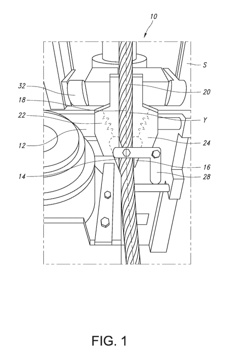
6 [0024] Referring to Figures 1, 2, 3, and 4, a cable pusher 10
is provided. The cable pusher
7 10 may be used to insert a cable 20 into a borehole, such as in a surface
of a mine passage (such
8 as, for example the roof). In the illustrated embodiment, the cable
pusher 10 includes a clamp 12,
9 comprised of a housing 12a having bores 12b for receiving a pair of
independently movable jaws
14, 16. As a result of the relative orientation of the bores 12b, the jaws 14,
16 are arranged at
11 opposing angles from longitudinal the axis Y of a passage P for
receiving the cable 20. In the
12 illustrated embodiment, the axis X along which the jaws 14, 16 travel
forms an acute angle a,
13 which may be approximately 15 degrees relative to the axis Y, but the
value could vary depending
14 on the particular application.
[0025] The jaws 14, 16 each include engagement faces 14a, 16a for engaging
the cable 20.
16 These faces 14a, 16a may be arranged to be generally parallel to the
axis Y at all times, despite the
17 angular mounting of the jaws 14, 16. The faces 14a, 16a may also be
frictionally enhanced, such
18 as by including horizontal grooves, knurling, or the like, to create a
strong, but releasable, gripping
19 force on the relatively smooth outer surface of the cable 20 (which is
typically made of braided
steel wire).
21 [0026] As a result of the adaptation provided, the jaws 14, 16
are independently movable
22 toward and away from a centerline of the pusher 10, such as between a
first or closed position for
23 gripping the cable 20, and a second or open position (14', 16') for
releasing the cable, as can be
24 understood from comparing Figures 2 and 4. The jaws 14, 16 may be
normally biased toward the
first or closed position, and thus when in the second position, are constantly
forced along the axis
26 X to engage the cable 20 aligned with axis Y. The biasing force may be
provided by one or more
27 springs 22, 24, such as coil springs associated with the housing 12a,
such as by being recessed
28 within the bores 12b and also recessed within the upper portions of the
jaws 14, 16. The springs
29 22, 24 are arranged to normally urge the jaws 14, 16 along the axis X
and toward the axis Y, with
a spring constant selected to ensure a proper gripping force against the cable
20 (the nature of
31 which may vary) and yet one that can be overcome to allow for release
when desired, as outlined
4
CA 03123088 2021-06-11
WO 2020/132464
PCT/US2019/067889
1 further in the following description. While two springs are shown, it can
be appreciated that
2 biasing only one jaw 22 or 24 is possible.
3 [0027] As can be appreciated, the passage P is also open along
one side, such as the front
4 lateral side in use. This allows for the cable 20 to be inserted or
removed from a position between
the jaws 14, 16. A movable retainer 28 may also be provided to retain the
cable 20 in pusher 10
6 in a deployed position, but allow for the easy removal when desired.
7 [0028] As depicted in Figure 5, the pusher 10 may be mounted to
swing from a position in
8 line with an axis of the borehole to accommodate the shape of the cable
20 when it is not straight,
9 or is being advanced at an angle relative to the borehole axis. This
figure shows the pusher 10 in
a pivoted position resulting from its engagement of a curved portion of cable
20. With combined
11 reference to Figures 2 and 5, it can be understood that, in order to
achieve this pivoting movement,
12 the housing 12a may include a yoke with apertures 12c, each for
receiving a smooth shank of
13 opposed bolts 32 carried by an associated support structure S (which may
be adapted for moving
14 to and fro to advance the cable, as outlined further in the following
description).
[0029] With reference to Figures 6, 7, and 8, the cable pusher 10 may be
used in
16 conjunction with a drilling mast 40 for forming a borehole in the
surface of an underground mine
17 passage. The mast 40 may comprise a drill guide 42 for guiding a drill,
as well as an actuator,
18 such as a hydraulic cylinder 44, for advancing a support 46 for
temporarily engaging the surface
19 of the mine passage into which the borehole is formed. An actuator 48
may also be used to advance
and retract an associated drill head 50 along the mast 40 for using a drilling
element (steel) to form
21 the borehole. The cable pusher 10 may be mounted to the mast 40 via a
carriage 52 mounted for
22 lateral movement (note arrow Z). The carriage 52 may thus move to and
fro to reposition the drill
23 head 50 from alignment with the axis of the drilled hole and align the
pusher 10 with the drilled
24 hole (so that the axis of the drilled hole is generally coincident with
axis Y), and then back again.
[0030] In operation, once the borehole is formed (drilled) by a drill using
the drill head 50
26 and installation of the cable is desired, the pusher 10 is moved
laterally into alignment with the
27 borehole (which may be done manually or automatically). A distal end
portion of the cable 20 is
28 then inserted into the borehole, and a proximal end portion is passed
into the passage P and then
29 secured in place using the retainer 28. During the upward movement
(action arrow A in Figure
4A) resulting from an advance stroke of the carriage 52, it can be appreciated
that the jaws 14, 16
31 are forced against the cable 20, and thus provide a clamping force to
engage and move it farther
5
CA 03123088 2021-06-11
WO 2020/132464
PCT/US2019/067889
1 into the borehole. The biasing force of the springs 22, 24 may be such
that the jaws 14, 16 do not
2 fully reach the bottom of the associated bores when the cable 20 is
adequately gripped (note
3 intermediate position of jaws 14", 16" in Figure 4B).
4 [0031] Once the maximum advance is reached during an upstroke
(compare initial position
Tin Figure 4A with final position F in Figure 4B, reflecting the advance of
the cable 20 a distance
6 corresponding to the length of the actuator stroke), the feed may retract
to reverse the movement
7 of the carriage 52. As can be appreciated, during the downward movement
or retraction (arrow D
8 in Figure 4B), the springs 22, 24 may more fully or completely compress
to release the gripping
9 force, and the jaws 14, 16 thus slide along the cable 20 without gripping
and retracting it (note gap
G, which is exaggerated for purposes of illustration of the concept). Once the
bottom of the stroke
11 is reached, the feed may be reversed, at which point the jaws 14, 16 are
biased to fully engage a
12 proximal portion of the cable 20 and advance it into the borehole. As
can be appreciated, the
13 operation may be repeated as necessary or desired to advance the cable
into the borehole.
14 [0032] The cable 20 may include a pre-installed driving head
20a at a proximal end thereof,
as shown in Figure 9. As this head 20a is oversized relative to the passage P
and typically would
16 not fit therethrough, it can be appreciated that the open nature of the
design of pusher 10 allows
17 for the cable 20 to be withdrawn from the passage P once fully
installed. The driving head 20a (if
18 present) may then be associated with the drill head 50 and the
installation completed by
19 rotating/driving the cable 20 the remainder of the way into the borehole
(with the cured resin then
providing the desired securing function to provide support for the mine
passage). As indicated in
21 Figure 9, the cable 20 may also be provided with surface notches 20b
running transverse or
22 generally circumferentially, which serve to enhance the gripping force
established with the jaws
23 14, 16.
24 [0033] Figures 10-13 illustrate a version of the retainer 28
adapted to maintain the cable
pusher in an open condition, such as for loading the cable therein. As noted
above, the retainer 28
26 may be mounted for pivoting movement for covering the passage P, and may
be connected to a
27 support 60 for supporting the jaws 14, 16 in an open condition.
Specifically, each jaw 14, 16 may
28 be provided with a projection 14a, 16a, which is engaged by a depending
portion of the support 60
29 in the form of an inverted T-shaped member 62. The T-shaped member 62 is
partly inserted into
a channel 64 formed in the housing 12a in sliding engagement, and a linkage 66
connects the
31 member 62 for causing up and down movement relative to the pusher 10.
6
CA 03123088 2021-06-11
WO 2020/132464
PCT/US2019/067889
1 [0034] As perhaps best understood from Figures 12 and 13, the
retainer 28 in the open
2 position (arrow 0) raises the T-shaped member 62, which in turn engages
the projections 14a, 16a
3 of the jaws 14, 16. This overcomes the biasing force and maintains the
jaws 14, 16 in an open
4 condition to allow for a cable to be inserted into passage P. Closing the
retainer 28 (arrow C)
allows the jaws 14, 16 to then close (fully as shown, but of course in
gripping engagement with a
6 cable, if present). Loading and unloading of the cable is thus greatly
facilitated.
7 [0035] Figure 14 illustrates the carriage 52 for the drill head
50 mounted for lateral
8 movement (note arrow Z). As noted above, the carriage 52 may thus move to
and fro to move the
9 drill head 50 from alignment with the axis of the drilled hole and align
the pusher 10 (shown with
the optional retainer 28) with the drilled hole (so that the axis of the
drilled hole is generally
11 coincident with axis Y), and then back again. This may be achieved by
mounting the carriage 52
12 on generally parallel, horizontal guides 68 (only upper one shown), such
as for providing sliding
13 movement. The provision of wheels 70a on the carriage support 70 for
traversing the mast 40 in
14 the vertical direction V is also noted.
[0036] As illustrated in Figure 15, the cable pusher 10 may be associated
with a vehicle
16 80, which may include the mast 40. This allows for the cable pusher 10
to traverse about a mine
17 passage or other location where anchorage is needed. While a vehicle 80
with wheels is shown, it
18 can be appreciated that any type of ground-engaging arrangement for
causing movement, such as
19 crawler tracks, may be used. As can be appreciated, the pusher 10 may
also be used independent
of a vehicle as well, or in connection with other forms of mine machinery.
21 [0037] This disclosure may be considered to pertain to any one
or more of the following
22 items, whether considered alone or in any combination:
23 1. An apparatus for pushing a cable into a borehole in a surface of a
mine passage in
24 connection with an actuator, such as for example a drill mast having a
carriage capable of being
advanced and retracted along the drill mast, comprising:
26 a pusher comprising a pair of jaws for engaging the cable, the
pair of jaws being
27 biased toward a first position for engaging the cable during an advance
of the carriage, and
28 automatically movable to a second position for releasing from engagement
with the cable during
29 a retraction of the carriage.
7
CA 03123088 2021-06-11
WO 2020/132464
PCT/US2019/067889
1 2. The apparatus of item 1, wherein each of the jaws is biased along
an axis extending
2 at an acute angle relative to a longitudinal axis of a passage in the
pusher for receiving a portion
3 of the cable.
4 3. The apparatus of item 1 or item 2, wherein the pusher includes a
housing, and each
jaw is located within a bore in the housing.
6 4. The apparatus of item 3, wherein the bore includes a spring for
biasing the jaw.
7 5. The apparatus of any of items 1-4, wherein each jaw includes a
face for engaging
8 the cable, the face being generally parallel with a longitudinal axis of
the passage.
9 6. The apparatus of any of items 1-5, wherein the pusher is adapted
for pivotally
mounting to the carriage.
11 7. The apparatus of any of items 1-6, wherein the pusher includes a
passage for
12 receiving a portion of the cable.
13 8. The apparatus of item 7, wherein the passage includes a lateral
opening for
14 receiving the portion of the cable.
9. The apparatus of item 8, further including a retainer for retaining the
portion of the
16 cable within the passage.
17 10. An apparatus for pushing a cable into a borehole in a surface of
a mine passage,
18 comprising:
19 an actuator, such as a drill mast having a carriage capable of
being advanced and
retracted along the drill mast; and
21 a pusher pivotally mounted to the carriage, the pusher comprising
a pair of jaws for
22 engaging the cable, the jaws being biased toward a first position for
engaging the cable during an
23 advance of the carriage, and automatically movable to a second position
for releasing from
24 engagement with the cable during a retraction of the carriage.
11. The apparatus of item 10, wherein the drill mast includes a drill head
and is adapted
26 for moving out of alignment with an axis of the borehole and moving the
pusher into alignment
27 with the axis of the borehole.
28 12. The apparatus of item 11, wherein the drill head is mounted to
the carriage, which
29 mounted for moving laterally relative to the drill mast.
13. An apparatus for pushing a cable into a borehole in a surface of a mine
passage,
31 comprising:
8
CA 03123088 2021-06-11
WO 2020/132464
PCT/US2019/067889
1 a drill mast having a carriage capable of being advanced and
retracted along the
2 drill mast, and also capable of moving to align a drill head with an axis
of the borehole; and
3 a pusher for pushing the cable into the borehole, the pusher
connected to the drill
4 carriage.
14. The apparatus of item 13, wherein the pusher comprises a pair of jaws
for engaging
6 the cable, the jaws being biased toward a first position for engaging the
cable during the advance
7 of the carriage, and automatically movable to a second position for
releasing from engagement
8 with the cable during the retraction of the carriage.
9 15. A method of inserting a cable into a borehole using a drilling
mast, comprising:
gripping the cable using a pusher including a pair of opposed jaws during an
11 advance portion of a stroke of the drilling mast; and
12 releasing the jaws from gripping the cable during a return portion
of the drilling
13 mast stroke.
14 16. The method of item 15, further including repeating the
gripping step on a proximal
portion of the cable.
16 17. The method of item 15 or item 16, further including the step
of retaining a portion
17 of the cable in a laterally open passage of the pusher including the
pair of opposed jaws.
18 18. The method of any of items 15-17, wherein the cable includes a
driving head, and
19 further including the step of removing the cable from the laterally open
passage before the driving
head engages the pusher, and associating the driving head with a drill head.
21 19. The apparatus or method of any of the foregoing items, wherein
the cable includes
22 circumferential notches.
23 20. The apparatus or method of any of the foregoing items, further
including a vehicle.
24 21. The apparatus or method of any of the foregoing items, further
including means
(such as a support) for retaining the pair of jaws in an open condition for
loading the cable.
26 [0038] As used herein, the following terms have the following
meanings:
27 [0039] "A", "an", and "the" as used herein refers to both
singular and plural referents
28 unless the context clearly dictates otherwise. By way of example, "a
compartment" refers to one
29 or more than one compartment.
[0040] "About," "substantially," or "approximately," as used herein
referring to a
31 measurable value, such as a parameter, an amount, a temporal duration,
and the like, is meant to
9
CA 03123088 2021-06-11
WO 2020/132464
PCT/US2019/067889
1 encompass variations of +/- 20% or less, preferably +/-10% or less, more
preferably +/-5% or less,
2 even more 35 preferably +/-1% or less, and still more preferably +/-0.1%
or less of and from the
3 specified value, in so far such variations are appropriate to perform in
the disclosed invention.
4 However, it is to be understood that the value to which the modifier
"about" refers is itself also
specifically disclosed.
6 [0041] "Comprise", "comprising", and "comprises" and "comprised
of' as used herein are
7 synonymous with "include", "including", "includes" or "contain",
"containing", "contains" and
8 are inclusive or open-ended terms that specifies the presence of what
follows e.g. component and
9 do not exclude or preclude the presence of additional, non-recited
components, features, element,
members, steps, known in the art or disclosed therein.
11 [0042] The foregoing has been presented for purposes of
illustration and description. It is
12 not intended to be exhaustive or to limit the embodiments to the precise
form disclosed. Obvious
13 modifications and variations are possible in light of the above
teachings. All such modifications
14 and variations are within the scope of the appended claims when
interpreted in accordance with
the breadth to which they are fairly, legally and equitably entitled.
16
17
18