Note: Descriptions are shown in the official language in which they were submitted.
CA 03123169 2021-06-11
Title: Gas Nozzle for the Outflow of a Protective Gas Stream and Torch
with a Gas Nozzle
Description
The invention relates to a gas nozzle for the outflow of a shielding gas
stream according to
the generic part of claim 1, and to a torch neck with a gas nozzle according
to the generic
part of claim 11, to a torch according to the generic part of claim 15 as well
as to a method
for thermally joining at least one workpiece according to the generic part of
claim 16.
Thermal arc joining methods utilize energy to fuse the workpieces and to
connect them.
"MIG", "MAG" and "TIG" are standard welding methods that are employed in sheet
metal
processing.
When it comes to shielding gas-assisted arc welding methods employing a
consumable
electrode (MSG), "MIG" stands for "metal inert gas" and "MAG" stands for
"metal active
gas". In the case of shielding gas-assisted arc welding methods employing a
non-
consumable electrode (TSG), "TIG" stands for "tungsten inert gas". The welding
devices
according to the invention can be configured as machine-controlled welding
torches.
MAG welding is a metal shielding-gas (MSG) welding process with active gas in
which the
arc burns between a continuously fed, consumable wire electrode and the
material. The
consumable electrode supplies the filler material to form the weld seam. MAG
welding can
be easily and cost-effectively employed with almost all welding-appropriate
materials. In
this context, different shielding gases are employed, depending on the
requirements and on
the material.
In the case of metal shielding-gas (MSG) welding, the fed-in active gas
protects the
electrode, the arc and the welding bath vis-a-vis the atmosphere. This ensures
good welding
- 1 -
Date Recue/Date Received 2021-06-11
CA 03123169 2021-06-11
results with a high melting capacity under a wide array of conditions. As a
function of the
material, a gas mixture consisting of argon CO2, argon 02 or pure argon or
else pure CO2 is
used as the shielding gas. Depending on the requirements, different wire
electrodes are
employed. MAG welding is a robust, cost-efficient and versatile welding
process that is
well-suited for manual, mechanical and automated processes.
MAG welding is suitable for welding unalloyed or low-alloyed steel grades. As
a matter of
principle, high-alloyed steel grades and nickel-based alloys can also be
welded by means of
the MAG process. The content of 02 or CO2 in the shielding gas, however, is
small.
Varying arc types and welding processes such as the standard process or the
pulsed process
are employed, depending on the requirements being made of the weld seam and on
the
optimal welding result envisaged.
Arc welding devices generate an arc between the workpiece and a consumable or
non-
consumable welding electrode in order to fuse the material that is to be
welded. A stream of
shielding gas shields the material that is to be welded as well as the welding
site against the
atmospheric gases, mainly N2, 02, H2, that are present in the ambient air.
In this context, the welding electrode is provided on a torch body of a
welding torch that is
connected to an arc welding device. The torch body normally has a group of
internal
components that carry welding current and that conduct the welding current
from a source
of welding current in the arc welding device via the tip of the torch head to
the welding
electrode, where it then generates the arc to the workpiece.
The shielding gas stream flows around the welding electrode, the arc, the
welding bath and
the heat-affected zone on the workpiece, and in this process, it is fed to
these areas via the
body of the welding torch. A gas nozzle conveys the shielding gas stream to
the front end
of the torch head, where the shielding gas stream exits from the torch head
around the
welding electrode in an approximately annular pattern.
- 2 -
Date Recue/Date Received 2021-06-11
CA 03123169 2021-06-11
In the state of the art, as a rule, the gas is conveyed to the gas nozzle via
components made
of a material having low electric conductivity (polymers or oxide ceramics)
which can
concurrently serve as insulation.
During the welding procedure, the arc generated for the welding heats up the
workpiece
that is to be welded as well as any optionally added welding material, so that
these are
fused. The input of arc energy, the high-energy heat radiation and the
convection all give
rise to a significant input of heat into the head of the welding torch. Some
of the introduced
heat can be dissipated again by the shielding gas stream that is conveyed
through the torch
head or by the passive cooling in the ambient air as well as by heat
conduction into the hose
pack.
However, above a certain welding current load of the torch head, the heat
input is so high
that so-called active cooling of the torch head is necessary in order to
protect the employed
components against thermal material failure. Towards this end, the torch head
is actively
cooled with a coolant that flows through the torch head, thereby carrying away
the
unwanted heat that has been picked up during the welding process. For example,
de-ionized
water to which ethanol or propanol has been added can be employed as a coolant
for
purposes of providing protection against freezing.
Aside from welding, soldering is also an option when it comes to joining sheet
metal
components. Unlike in the case of welding, with soldering, it is not the
workpiece that is
melted but rather only the filler material. The reason is that, in soldering,
two edges are
joined together by the solder as the filler material. The melting temperatures
of the solder
material and of the component materials are very different, which is why only
the solder
melts during processing. Aside from TIG, plasma and MIG torches, lasers are
likewise
suitable for soldering.
- 3 -
Date Recue/Date Received 2021-06-11
CA 03123169 2021-06-11
The arc soldering processes can be broken down into metal shielding gas
soldering (MSG-
S) processes and tungsten-shielding gas soldering (TSG-S) processes. For the
most part,
copper-based materials in wire form, whose melting ranges are lower than those
of the base
materials, are used here as the filler material. In terms of the equipment
employed, the
principle of MSG arc soldering is largely identical to MSG welding, using
filler material in
wire form. In the case of TSG soldering, the filler material in wire form is
fed into the arc
either manually or mechanically from the side. In this process, the filler
material can be fed
in either de-energized as a cold wire or else energized as a hot wire. Greater
melting
capacities are achieved with a hot wire although the arc is influenced by the
additional
magnetic field.
As a rule, arc soldering is used on surface-finished or uncoated thin-gauge
sheet metal
since, among other things, the lower melting temperature of the solder in
comparison to
welding accounts for less thermal stress for the components, and the coating
is only
damaged to a lesser extent. No appreciable melting of the base material occurs
in the case
of arc soldering.
The arc soldering processes are normally employed on uncoated and metal-coated
sheet
metal made of unalloyed or low-alloyed steel within the thickness range of up
to
approximately 3 mm at the maximum.
Usually, argon II or argon mixtures with admixtures of CO2, 02 or 112
according to DIN
ISO 14175 are used for arc soldering. Commercially available TIG torches can
be
employed for TIG soldering.
European patent specifications EP 2 407 267 B1 and EP 2 407 268 B1 disclose a
welding
torch with a shielding-gas feed means, a torch connecting block, a torch neck
that adjoins
one end of the torch connecting block, and a torch head situated on the other
end of the
- 4 -
Date Recue/Date Received 2021-06-11
CA 03123169 2021-06-11
torch neck, wherein the torch neck has an inner pipe, an outer pipe and
insulation tubing
situated between the inner pipe and the outer pipe.
Such welding torches are used in the state of the art for metal inert gas
(MIG) welding,
among others. For instance, such a welding torch is described in German patent
application
DE 10 2004 008 609 Al. With this welding torch, the welding current is fed via
the contact
nozzle to the welding wire located in the inner pipe. In this context, the
external parts of the
torch are electrically insulated from the inner pipe in order to prevent the
welding current
from flowing via the torch housing. During the welding process, the welding
wire heats up
and this heat is partially conveyed into the welding torch.
Generically, the welding gas that is being used in the welding process anyway
is mostly an
inert shielding gas that can be employed very effectively to cool the inner
pipe. Effective
cooling of the inner pipe can be achieved if the gas flows in flat channels
along the outside
of the inner pipe. The state of the art uses an outer sleeve on the inner pipe
in order to
create gas-flow channels on the outside of the inner pipe. The assembly
consisting of the
inner pipe and the outer sleeve is then insulated from an outer housing pipe
by means of
insulation tubing.
Generically, the shielding gas is at first fed through the shielding-gas feed
means which is
typically in the form of a hole drilled in the torch connecting block. Since
the shielding gas
is fed asymmetrically to the inner pipe, the shielding gas should be diffused
around the
inner pipe as uniformly as possible. Towards this goal, for example, European
patent
specification EP 2 407 267 Bl proposes for the outer ring channel to be formed
inside the
torch connecting block and around the inner pipe, so that the shielding gas
can be diffused
around the inner pipe. Therefore, the shielding gas starts flowing from the
drilled hole in
the connecting block via the outer ring channel and the radial gas channels to
the interstice
between the inner pipe and the insulation tubing or optionally also to the
interstice between
the insulation tubing and the outer pipe.
- 5 -
Date Recue/Date Received 2021-06-11
CA 03123169 2021-06-11
European patent application EP 0 074 106 Al discloses a water-cooled shielding-
gas
welding torch for welding with a continuously consumable electrode for
automatic welding
devices. Periodic cleaning by means of air blasts is to be effectuated by the
coaxial
arrangement of two outer profile pipes which are electrically insulated from
each other and
whose grooves are configured as channels. These channels extend from the torch
head that
has the gas nozzle on a gas-nozzle holder all the way to a torch body. At the
same time, the
shielding-gas inner channels should serve to feed blow-out air into the gas
nozzle during
the periodic cleaning of the gas nozzle. The outer water channels extend all
the way to the
gas nozzle holder so that this holder is cooled directly. Due to a special
configuration of the
torch body and of the connecting parts, the shielding gas or compressed air
for the blow-out
air and the cooling water is fed to the coaxially arranged profile pipes.
European patent application EP 2 487 003 Al discloses a welding gun of an arc-
welding
device that, at one welding end, has a sleeve-shaped gas nozzle with a wall
that surrounds a
passage channel, and that, in the gas nozzle, has a gas diffuser with gas
outflow openings.
The gas nozzle has a connecting structure on one connection end in the
interior on the
inside of the wall. In the gas nozzle, a continuous, surrounding projection is
formed on the
inside of the wall behind the connecting structure as seen in the direction of
the gas outlet
end, and this projection brings about a reduction in the cross section of the
passage channel
vis-a-vis the surroundings of the projection. Moreover, as seen in the
direction of the gas
outlet end, the gas diffuser has a corresponding setback in front of the gas
outlet openings.
A disadvantage of this is that the gas diffuser is protected and held by means
of an annular
groove but not firmly connected to it. For this reason, there is no guarantee
that the gas
diffuser cannot be lost if it is not screwed in. After all, the gas nozzle is
screwed onto this
torch having a wire guide and a gas diffuser. Accordingly, the gas diffuser is
not connected
in a captive manner to the gas nozzle but rather to the rest of the torch.
- 6 -
Date Recue/Date Received 2021-06-11
CA 03123169 2021-06-11
Automatic cleaning of the gas nozzle described in European patent application
EP 2 487 003 Al is likewise not possible since the gas nozzle is only held by
the annular
groove but is not firmly connected to it. For this reason, it is not secured
against turning,
even when it is screwed in.
Japanese published unexamined patent application JPA 1985072679 discloses an
arc-
welding method. A shielding gas flows centrally from a gas nozzle arranged in
an inner
pipe. A gas diffuser that can mounted on the torch body is made of an
electrically insulating
material.
Japanese registered utility model application JPU 11982152386 discloses an arc-
welding
torch with a consumable electrode, wherein the shielding gas is fed centrally
into the torch
neck and exits through holes in a gas diffuser. The gas diffuser is made of an
electrically
insulating material.
German translation of published international application DE 602 24 140 T2
discloses a
welding torch for use in metal shielding-gas welding. The welding torch has a
neck section
and a diffuser at a first end of the neck section. A contact tip extends from
the diffuser. A
connection means is situated at a second end of the neck section and serves to
connect the
neck section to a power cable assembly. The neck section has an electric
conductor and a
passage that extends longitudinally. A gas serves to protect the welding
points from
atmospheric impurities if the welding points are created using the welding
torch. The gas
flows out of the welding torch from the power cable assembly along the passage
and
through openings in the diffuser.
When it comes to welding torches of the generic type, especially MSG (metal
shielding-
gas) welding torches, among other things, the contacting of the wire electrode
to the
welding potential in the flow nozzle, takes place at the front end, and so do
the rectification
and laminarization of the shielding gas stream to the material to be welded,
especially to the
- 7 -
Date Recue/Date Received 2021-06-11
CA 03123169 2021-06-11
workpiece. Moreover, in the case of liquid-cooled systems, some of the process
heat is
transferred to the cooling circulation system.
Therefore, for optimal cooling of the wearing parts, for example, the contact
tip, the
distance from the heat source, that is to say, from the welding process, to
the cooling
circulation system in the case of liquid cooling, should be designed to be as
short as
possible. The rectification and laminarization of the shielding gas stream
call for a
sufficient retention time brought about by a suitable geometry in the
shielding gas feed
means, especially inside of the wearing parts. Moreover, the outer pipe and
the inner pipe
of the MSG welding torch also have to be electrically insulated from each
other.
When the welding process is being carried out, depending on the process
parameters, more
or less spatter can adhere to the wearing parts. In MSG welding torches, as a
rule, these
adhesions are removed in automatically controlled systems by means of a motor-
powered
cleaning apparatus using a milling tool. The wearing parts, particularly the
gas nozzle or the
contact tip as well as an insulator, all have to withstand these mechanical
stresses.
In the case of prior-art torch necks, for example, the model series "ABIROB
W500"
manufactured by the applicant, the shielding gas can be fed centrally in the
inner pipe. The
term "central gas feed" designates those designs in which the shielding gas
can be fed
together with the filler wire in the interior of the inner pipe. Consequently,
the inner pipe
can be configured with a single wall. Owing to the holes in the nozzle holder,
the shielding
gas stream radially enters into a spatter protection means and exits in the
direction of the
gas nozzle. The spatter protection means is configured in such a way that, in
addition to
diffusing the gas, it also provides electric insulation.
When the contact tip and the gas nozzle are being cleaned, for instance, with
a milling tool,
the spatter protection means is at a sufficient distance from the milling tool
so that it is not
damaged.
- 8 -
Date Recue/Date Received 2021-06-11
CA 03123169 2021-06-11
In the case of other prior-art torch necks, especially those of the model
series "ABIROB
W600" manufactured by the applicant, the shielding gas is fed decentrally in
the inner pipe.
When it comes to a decentralized gas feed, the shielding gas is conveyed in a
double wall of
the inner pipe. In other words, the inner pipe is then a composite pipe or a
combined pipe-
in-pipe connection, wherein one pipe is profiled so that interstices can form
between the
two pipe walls. The shielding gas stream exits radially via holes in the inner
pipe. The
shielding gas then enters the gas nozzle via a gas diffuser. The gas diffuser
is made of a
phenolic compressed compound and it functions as an electric insulator by
means of which
the shielding gas is diffused and the insulation between the inner pipe and
the outer pipe is
effectuated at the appertaining ends of the pipes. For this reason, the gas
holes cannot be
cleaned at the same time as the cleaning of the flow nozzle and of the gas
nozzle with a
milling tool. The gas diffuser is mounted so as to be rotatable around the
rotational axis of
the milling tool. As a result, even though the mechanical stress caused by
removed spatter
during the cleaning procedure is minimized, optimal cleaning cannot be
achieved by means
of the milling tool. In other words, with this design, the use of (compressed-
air operated)
milling tools is not possible. As an alternative here, the state of the art
offers a spatter
protection means which ensures insulation, as a result of which, however, the
positive
effect of a laminar gas feed through the gas diffuser cannot be implemented.
In the case of other prior-art torch necks of the model series "ABIROB TWIN
600W"
manufactured by the applicant, the shielding gas is fed decentrally in the
inner pipe. The
shielding gas stream exits radially via holes drilled in the inner pipe. The
shielding gas
flows axially to a spatter protection means which once again feeds it radially
into the gas
nozzle. The gas diffuser is made of a phenolic compressed compound and the
spatter
protection means is made of fiberglass-silicone. The gas diffuser and the
spatter protection
means are mounted so as to be rotatable. As a result, it is likewise not
possible to clean the
gas holes at the same time as the cleaning of the contact tip and the gas
nozzle with the
milling tool.
- 9 -
Date Recue/Date Received 2021-06-11
CA 03123169 2021-06-11
On the basis of the preceding elaborations, it follows that the structural
requirements made
of flow laminarization run counter to attaining a maximized transfer of the
process heat.
Moreover, a drawback of the prior-art torches is that automated cleaning, for
instance, by
means of a milling tool, is not possible without causing damage to the wearing
parts.
Furthermore, a disadvantage of the prior-art torches is that the gas nozzle
and the gas
diffuser are not a single module, but rather, separate components that can
easily be lost,
particularly when they are being replaced, since they are not captively joined
to each other.
Before the backdrop of the above-mentioned drawbacks, the invention is based
on the
objective of putting forward an improved gas nozzle and an improved torch neck
that allow
automated cleaning of the torch, especially by means of a milling tool, even
if the gas feed
for a shielding gas stream flowing laminarly is decentralized, that is to say,
through
channels inside a (composite) inner pipe.
This objective is achieved by means of a gas nozzle for the outflow of a
shielding gas
stream according to claim 1 and by a torch neck for thermally joining at least
one
workpiece, especially for arc joining, preferably arc welding or arc
soldering, according to
claim 11 as well as by means of a torch having such a torch neck according to
claim 15, and
by a method for thermally joining at least one workpiece according to claim
16.
Presentation of the invention
According to the invention, a gas nozzle is provided for the outflow of a
shielding gas
stream out of a gas outlet having a gas diffuser section, wherein the gas
nozzle, at least in a
partial area of the gas diffuser section, is configured with a double wall in
order to create a
flow space for the shielding gas stream.
- 10 -
Date Recue/Date Received 2021-06-11
CA 03123169 2021-06-11
In this manner, an additionally delimited flow space or a hollow space is
created inside the
module, that is to say, between the gas nozzle and the gas diffuser section,
or else the
transitions to this flow space or out of this flow space are created.
The flow channel for the shielding gas stream is lengthened by diverting the
shielding gas
stream in the double-walled gas diffuser section so that the desired laminar
flow is adjusted
at the front end of the torch head, in spite of the fact that, for purposes of
attaining a
maximized transfer of process heat, it has a shorter gas nozzle than prior-art
systems.
The gas nozzle is shortened as compared to prior-art nozzles in order to
position the liquid
cooling as close as possible to the heat source (welding process), that is to
say, the distance
from the heat source to the cooling circulation system is as short as
possible.
With a decentralized gas diffusion, the diffusion and laminarization of the
shielding gas
stream in the gas nozzle are no longer implemented via the inner pipe or the
nozzle holder.
Moreover, the holes of the separate gas diffuser cannot be mechanically
cleaned using a
milling tool. In this manner, the laminar flow can form at the front end of
the torch head,
even in the case of the shortened gas nozzle. Owing to the configuration
according to the
invention of the gas nozzle with an additionally delimited flow space inside
the module,
that is to say, between the gas nozzle and the gas diffuser section, the
minimal distance
from the source of process heat to the cooling circulation system allows the
shielding gas
stream to be laminarized and, at the same time, the gas holes of the
integrated gas diffuser
can be automatically cleaned using the milling tool. In other words, the torch
can withstand
automated cleaning by means of the milling tool.
According to a first advantageous refinement of the invention, the gas
diffuser section and
the gas nozzle are formed monolithically. For instance, the gas nozzle with
the gas diffuser
section can be made particularly easily and efficiently employing 3D printing.
- 11 -
Date Recue/Date Received 2021-06-11
CA 03123169 2021-06-11
As an alternative, it is conceivable for the gas diffuser section to be formed
by a gas
diffuser that is attached to the gas nozzle. In this manner, the gas nozzle
and the gas
diffuser form a module. Moreover, the loss of components is prevented in that
the gas
diffuser section is captively joined to the gas nozzle. Particularly when the
gas nozzle is
being replaced, that is to say, also when it is not screwed to the torch, the
gas diffuser is
captively held on the gas nozzle.
According to another advantageous configuration of the invention, it is
provided for the gas
diffuser section to have at least one gas outlet opening along its
circumference, especially
several gas outlet openings, arranged approximately at the same distance from
each other,
so that the gas outlet is fluidly connected to the gas outlet opening(s). It
is through these gas
outlet openings that the shielding gas flows in a uniformly diffused manner
along the
circumference as a function of the radial distribution of the openings. The
gas exiting via
the openings is thus deflected and diverted in the gas nozzle, resulting in an
improved flow
of the shielding gas in the direction of the gas outlet in terms of the
laminarity.
For this reason, it is advantageous to arrange the gas outlet openings in an
additional
component that is mounted on the gas nozzle and that can withstand cleaning
using a
milling tool. At the same time, the module consisting of the gas nozzle and
the additional
component creates an extension of the flow channel for the shielding gas where
the desired
laminar flow can already be formed at the front end of the torch neck.
In an advantageous refinement of the invention, the inner diameter of the gas
nozzle
defined by the gas nozzle and the adjacent gas diffuser section surface is
configured so as to
be uniform upstream from the gas stream or else conically decreasing, that is
to say,
tapered. In this manner, the milling tool, which is especially guided by a
machine, can be
inserted into the gas nozzle without any problem and can be moved all the way
to the gas
outlet openings, thus achieving a simple cleaning of the gas nozzle and of the
gas outlet
openings.
- 12 -
Date Recue/Date Received 2021-06-11
CA 03123169 2021-06-11
Another advantageous variant of the invention provides for the gas diffuser to
be made of a
metal material, especially copper or of a copper alloy or else of a ceramic. A
metal
material, however, is particularly advantageous in this context since the gas
outlet openings
cannot undergo automated cleaning with a milling tool in the case of the usual
ceramic or
polymer materials. Although modern machinable glass ceramics can be used, as a
rule, they
are very expensive and laborious to press.
This is why at least the gas diffuser section of the gas nozzle is preferably
made of a metal
material in order to allow automated cleaning of the gas holes, especially in
the case of a
decentralized gas diffusion. Moreover, damage during milling is very unlikely
to occur
since metal material exhibits a high impact resistance. A high degree of
hardness is
required of the material in order to withstand the abrasive forces during
cleaning with a
milling tool. As set forth in the invention, implementation using impact-
resistant, hard and
temperature-resistant non-metallic materials is likewise conceivable.
In a refinement of the invention, the gas diffuser is essentially flush with
the gas nozzle, at
least in certain sections. In this manner, the milling tool, which is
especially guided by
machine, can be easily inserted into the gas nozzle and moved all the way to
the gas outlet
openings, so that optimal cleaning is possible. The internal components,
especially the
contact tip and its holder, do not need to be modified for this purpose.
According to another advantageous embodiment of the invention, the gas
diffuser is joined
to the gas nozzle with a positive and/or a non-positive and/or a bonded
connection.
The term "positive or non-positive connections" is to be understood such that
they are
based on the fact that connecting elements transmit forces in that they press
the joining
surfaces against each other. A friction resistance that is greater than the
forces acting onto
- 13 -
Date Recue/Date Received 2021-06-11
CA 03123169 2021-06-11
the connection from the outside is created between the surfaces. In the case
of a non-
positive connection, forces and torques are transmitted by friction forces.
Positive connections are created in that the shape of the workpieces or
connecting elements
that are to be connected allow the force transmission, thus creating the
cohesion. Positive
connections are generated by the intermeshing of at least two mating parts. As
a result, the
mating parts cannot become detached, even with or without an interruption of
the
transmission of force. To put it in a different way, in a positive connection,
one of the
connection parts stands in the way of the other one. With a positive
connection, the
workpieces are connected by shapes that fit into each other.
Bonded connections are created by integrally uniting materials, that is to
say, the
workpieces are joined together by cohesion (cohesive force) and adhesion
(adhesive force).
In other words, the connecting parts are held together by forces on the atomic
or molecular
level. At the same time, these are undetachable connections such as, for
example, soldering,
welding, gluing or vulcanizing, which can only be separated by destroying the
connecting
means.
According to another advantageous variant of the invention, it is provided for
the gas
diffuser to be detachably connected to the gas nozzle, especially by being
screwed or
pressed into it. As an alternative, it can be provided for the gas diffuser to
be firmly
connected to the gas nozzle, especially by being glued on, soldered to or
pressed into the
gas nozzle. In this manner, a positive and/or non-positive connection of the
gas diffuser to a
welding torch is achieved. Incidentally, the term "detachable connections"
refers to the fact
that they can be separated without a component or the connecting means being
destroyed in
the process. In contrast, undetachable connections can only be separated by
destroying the
component or the connecting means.
- 14 -
Date Recue/Date Received 2021-06-11
CA 03123169 2021-06-11
Moreover, the gas diffuser can be configured so as to be annular, rotation-
symmetrical or
slotted. Preferably, eight rotation-symmetrical outlet openings are used and
the gas diffuser
is pressed into the gas nozzle over an edge surface situated on the outer
circumference of
the gas diffuser. Advantages of the embodiment with eight holes are that this
provides
sufficient "accumulation surface" for shielding gas while, at the same time,
eight outlet
openings are enough to attain the requisite volume flow for a stable joining
process.
According to an independent idea of the invention, a torch neck for thermally
joining at
least one workpiece, especially for arc joining, preferably for arc welding or
arc soldering,
is provided, and it has an electrode arranged in the torch neck or a wire for
generating an
arc between the electrode or the wire and the workpiece. Moreover, the torch
neck has a gas
nozzle for the outflow of a shielding gas stream out of a gas outlet. This gas
nozzle can be a
gas nozzle like the one described above.
As mentioned above, the welding process involving welding torches,
particularly machine
torches, can give rise to impurities on the gas nozzle and on the gas outlet
openings. These
contaminated components are cleaned by means of a milling tool and are freed
of weld
spatter in this manner. Consequently, the wearing parts, especially the gas
nozzle, the
contact tip or the insulation all have to withstand the mechanical stress
during milling.
In the state of the art, these gas outlet openings are located on a polymer or
ceramic
material component which concurrently serves as electric insulation between
the inner and
outer pipes of the torch head. A disadvantage here is that the milling tool
used for cleaning
does not reach all to way to the appertaining polymer or ceramic material
component. On
the other hand, the risk of damage to the wearing parts caused by the milling
tool would be
far too great.
These disadvantages are avoided in the case of the torch neck according to the
invention.
Particularly when it comes to torches with an inner and an outer pipe, the
transfer of current
- 15 -
Date Recue/Date Received 2021-06-11
CA 03123169 2021-06-11
and process heat can only take place via the inner pipe. For this reason, it
is favorable for
the shielding gas stream to be fed via the outer pipe or between the inner and
outer pipes. In
order to increase the time for the flow laminarization at the front end of the
torch, a
provision is made for the additional cross-sectional and directional-flow
modifications
based on the geometry of the gas nozzle.
The configuration of the torch neck with an appropriate geometry of the gas
nozzle having
a gas diffuser section and gas outlet openings ¨ wherein the gas nozzle, at
least in a partial
area of the gas diffuser section, is configured with a double wall in order to
create a flow
space for the shielding gas stream ¨ ensures a sufficient retention time for
the rectification
and laminarization of the shielding gas stream due to the suitable geometry,
even at a small
distance from the source of heat.
According to a first advantageous embodiment of the invention, an inner pipe
of the torch
neck that is electrically connected to a contact tip is electrically insulated
by an electric
insulator vis-a-vis an outer pipe of the torch neck that is at a distance from
the inner pipe.
In the prior-art torches, an insulated gas diffuser is employed which not only
diffuses the
shielding gas but also effectuates the insulation between the inner and outer
pipes at the
appertaining pipe ends. This design does not allow automated cleaning,
especially using a
compressed air-powered milling tool. As an alternative, the state of the art
suggests a
spatter protection means which ensures insulation but, as a result, the
positive effect of a
laminar gas feed through the gas diffuser cannot be achieved.
In the case of a decentralized gas feed, the shielding gas is fed in a double
wall of the inner
pipe. As a result, the inner pipe is actually a composite pipe or a combined
pipe-in-pipe,
wherein one pipe is profiled so that interstices are formed between the two
pipe walls.
- 16 -
Date Recue/Date Received 2021-06-11
CA 03123169 2021-06-11
The electric insulation is situated between the inner pipe and the outer pipe,
preferably with
a cover at the end of both pipes. In this context, the outer parts of the
torch are electrically
insulated from the inner pipe in order to prevent the welding currents from
flowing over the
torch housing. During the welding process, the welding wire heats up and this
heat is
partially fed into the welding torch.
It can be provided for the insulation to be configured in such a way that its
function is
separate from the function of feeding the gas. The wearing part for the
electric insulation
between the inner and outer pipes can be designed so as to be simpler and thus
more cost-
effective. Moreover, it is possible to use the milling tool for the cleaning
without causing
damage to the wearing parts.
Owing to the separation between the insulation and the flow feed for the
spatter protection
means, the insulation can be configured with a considerably simpler structure
and a thick
wall, and can be, for example, in the form of a cover and a spacer at the end
of the front
pipe ends of the inner and outer pipes in the form of the gas nozzle tip
holder. This
translates into a marked improvement, especially of the crash safety, that is
to say, the
positional stability of the torch neck under abrupt mechanical stress,
particularly if the
welding torch collides with the workpiece, in addition to which a non-
insulating gas
diffuser or gas diffuser section can be implemented in the gas nozzle.
In another advantageous refinement of the torch neck according to the
invention, a filter
ring made of sintered material is provided for pressure-reduction purposes,
wherein the
filter ring is installed in the gas nozzle downstream in a partial area of the
gas diffuser
section that is configured with a double wall. The shortening of the gas
nozzle means that
the retention time of the shielding gas in the nozzle might no longer be
enough to ensure
laminarization of the gas. This is why the filter ring made of sintered
material is provided
for pressure-reduction purposes.
- 17 -
Date Recue/Date Received 2021-06-11
CA 03123169 2021-06-11
According to another advantageous embodiment of the invention, a spatter
protection
means is provided for protection against weld spatter. The shielding gas flows
via the gas
diffuser or via the gas diffuser section axially to the spatter protection
means and is fed
radially by the latter once again into the gas nozzle. The spatter protection
means preferably
consists of a temperature-resistant insulator such as fiberglass-filled PTFE
and, during
cleaning of the contact tip and the gas nozzle using the milling tool, it is
at a sufficient
distance to the latter so that the spatter protection means is not damaged by
the milling tool.
According to another independent idea of the invention, a torch is provided
which has a
neck, especially a neck of the kind described above.
According to another independent idea of the invention, a method is provided
for thermally
joining at least one workpiece, especially for arc joining, preferably arc
welding or arc
soldering, having an electrode for generating an arc between the electrode and
the
workpiece. A shielding gas stream flows out of the gas nozzle, especially a
gas nozzle of
the kind described above. The direction of flow of the shielding gas is
modified at least
once by means of a gas diffuser section or a gas diffuser so that the duration
of flow is
prolonged or the flow path of the shielding gas stream inside the gas nozzle
is lengthened,
wherein the shielding gas stream surrounds the electrode essentially annularly
at the gas
outlet of the gas nozzle.
Additional objectives, advantages, features and application possibilities of
the present
invention can be gleaned from the description below of an embodiment making
reference to
the drawing. In this context, all of the described and/or depicted features,
either on their
own or in any meaningful combination, constitute the subject matter of the
present
invention, also irrespective of their compilation in the claims or in the
claims to which they
refer back.
In this context, the following is shown, at times schematically:
- 18 -
Date Recue/Date Received 2021-06-11
CA 03123169 2021-06-11
Figure 1 part of a torch neck of a welding torch having a gas nozzle,
Figure 2 a detailed view of the gas nozzle with a gas diffuser section,
Figure 3 a detailed view of the gas nozzle, wherein the gas diffuser
section and the
gas nozzle are configured monolithically,
Figure 4 a sectional view of the torch neck as shown in Figure 1, and
Figure 5 a part of a torch neck as shown in Figures 1 and 7, with a
milling tool.
For the sake of clarity, identical components or those having the same effect
are provided
with the same reference numerals in the figures of the drawing shown below,
making
reference to an embodiment.
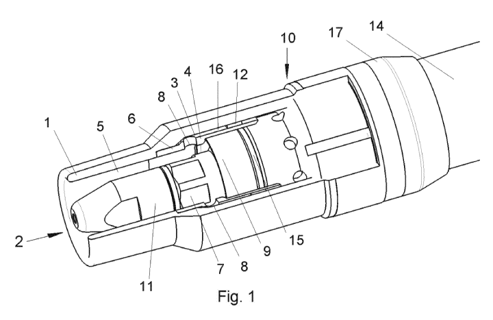
Figure 1 shows a torch neck 10 with a nozzle tip holder 7 of a welding torch
for thermally
joining at least one workpiece, especially for arc joining, preferably arc
welding or arc
soldering. "MIG", "MAG" and "TIG" are standard welding methods that are
employed in
sheet metal processing.
Figure 5 differs from Figure 1 in that a milling tool 18 is additionally
depicted.
When it comes to shielding gas-assisted arc welding methods employing a
consumable
electrode (MSG), "MIG" stands for "metal inert gas" and "MAG" stands for
"metal active
gas". MAG welding is a metal shielding-gas process (MSG) with active gas in
which the
arc burns between a continuously fed, consumable wire electrode and the
material. The
consuming electric supplies the filler material to form the weld seam.
- 19 -
Date Recue/Date Received 2021-06-11
CA 03123169 2021-06-11
In the case of shielding gas-assisted arc welding methods employing a non-
consumable
electrode (TSG), "TIG" stands for "tungsten inert gas". The welding devices
according to
the invention can be configured as machine-controlled welding torches.
Arc welding devices generate an arc between the workpiece and a consumable or
non-
consumable welding electrode in order to fuse the material that is to be
welded. A shielding
gas stream shields the material that is to be welded as well as the welding
site against the
atmospheric gases, mainly N2, 02, H2, that are present in the ambient air.
In this context, the welding electrode is provided on a torch body of a
welding torch that is
connected to an arc welding device. The torch body normally has a group of
internal
components that carry the welding current and that conduct the welding current
from a
source of welding current in the arc welding device to the tip of the torch
head and to the
welding electrode, where it then generates the arc to the workpiece.
The shielding gas stream flows around the welding electrode, the arc, the
welding bath and
the heat-affected zone on the workpiece, and in this process, it is fed to
these areas via the
body of the welding torch. A gas nozzle 1 conveys the shielding gas stream to
the front end
of the torch head, where the shielding gas stream exits from the torch head
around the
welding electrode in an approximately annular pattern.
In the present embodiment, the torch neck 10 shown in Figures 1 and 5 and
belonging to
the torch head of the welding torch comprises the gas nozzle 1 for the outflow
of a
shielding gas stream out of a gas outlet 2 located at the front end of the gas
nozzle 1. Such
gas nozzles 1 are presented in detail in Figures 2 and 3.
Figures 1 to 3 and 5 also show that the gas nozzle 1, at least in a partial
area of the gas
diffuser section 3, is configured with a double wall in order to create a flow
space 16 for the
shielding gas stream. Thus, the configuration of the torch neck 10 with an
appropriate
- 20 -
Date Recue/Date Received 2021-06-11
CA 03123169 2021-06-11
geometry of the gas nozzle 1 having the gas diffuser section 3 and the gas
outlet openings 8
ensures a sufficient retention time for the rectification and laminarization
of the shielding
gas stream, even at a small distance from the source of heat.
The embodiments of the gas nozzle 1 as shown in Figure 2 and Figure 3 differ
in that the
gas diffuser section 3 and the gas nozzle 1 as shown in Figure 3 are formed
monolithically.
For instance, the gas nozzle with the gas diffuser section can be made
particularly easily
and efficiently employing 3D printing.
In contrast, Figure 2 shows that the gas diffuser section 3 is formed by a gas
diffuser 4
installed on the gas nozzle 1. In this manner, the gas nozzle 1 and the gas
diffuser 4
constitute a module.
In both embodiments of the gas nozzle 1 according to Figure 2 and Figure 3,
the gas
diffuser section 3 has several gas outlet openings 8 arranged along its
circumference
approximately at an equal distance from each other, so that the gas outlet 2
is fluidly
connected to the gas outlet openings 8.
It is through these gas outlet openings 8 that the shielding gas flows in a
uniformly diffused
manner over the circumference as a function of the radial distribution of the
openings 8.
The shielding gas stream exiting via the gas outlet openings 8 is thus
deflected and diverted
in the gas nozzle 1, resulting in an improved flow of the shielding gas in the
direction of the
gas outlet 2 in terms of the laminarity.
The module consisting of the gas nozzle 1 and the gas diffuser 4 or gas
diffuser section 3
creates an extension of the flow channel for the shielding gas where the
desired laminar
flow can already be formed at the front end of the torch neck.
- 21 -
Date Recue/Date Received 2021-06-11
CA 03123169 2021-06-11
As can also be seen in Figures 1 to 5, the inner diameter 5 of the gas nozzle
1 defined by
the gas nozzle 1 and by the adjacent gas diffuser section surface 6 is
configured so as to be
uniform upstream from the shielding gas stream or else conically decreasing,
that is to say,
tapered. The welding process involving welding torches, particularly machine
torches, can
give rise to impurities on the gas nozzle 1 and on the gas outlet openings 8.
These
contaminated components are cleaned in an automated process by means of a
milling tool
18, and are freed of weld spatter in this manner. Consequently, the wearing
parts, especially
the gas nozzle 1, the contact tip 11 or the spatter protection means 19 all
have to withstand
the mechanical stress during milling. Such a milling tool 18 is depicted in
Figure 5.
Owing to the configuration of the inner diameter 5 of the gas nozzle 1, the
machine-guided
milling tool 18 can be inserted into the gas nozzle 1 without any problem and
moved all the
way to the gas outlet openings 8 that are to be cleaned. For this reason, the
gas diffuser 4 or
gas diffuser section 3 arranged on the gas nozzle 1 can withstand being
cleaned by means
of a milling tool 18.
In the case of a multi-part configuration of the gas nozzle 1 having a gas
diffuser 4 as
shown in Figure 2, the gas diffuser 4 is essentially flush with the gas nozzle
1, at least in
certain sections. This allows optimal cleaning of the gas nozzle 1. The inner
components,
especially the contact tip 11 and its holder, do not need to be modified for
this purpose.
Consequently, automated cleaning using the milling tool 18 is easily possible.
In the case of the configuration of the gas nozzle 1 as shown in Figure 2, the
gas diffuser 4
is joined to the gas nozzle 1 with a positive and/or a non-positive and/or a
bonded
connection 1. In particular, it is conceivable for the gas diffuser 4 to be
detachably
connected to the gas nozzle 1, especially by being screwed or pressed into it.
As an
alternative, it is conceivable for the gas diffuser 4 to be firmly connected
to the gas nozzle
1, especially by being glued on, soldered to or pressed into the gas nozzle 1.
- 22 -
Date Recue/Date Received 2021-06-11
CA 03123169 2021-06-11
As can be seen in the sectional view of the torch neck 10 as shown in Figure 4
as well as in
Figure 1 and Figure 5, an inner pipe 13 of the torch neck 10 that is
electrically connected to
a contact tip 11 is electrically insulated by the insulation cap 15 vis-a-vis
the outer pipe 14
of the torch neck 10 that is at a distance from the inner pipe 13, preferably
with a cover at
the end of both pipes 13 and 14. The external parts of the torch or torch neck
10 are
electrically insulated from the inner pipe 13 in order to prevent the welding
currents from
flowing over the torch housing.
Here, the gas nozzle carrier 17 not only has a function as a carrier for the
gas nozzle 1 but
also the function of diffusing the shielding gas. For this reason, the spatter
protection means
9 and the insulation cap 15 can be configured so that their function is
separate from the
function of feeding the shielding gas. Therefore, the spatter protection means
9 can be
configured so as to have a solid wall and consequently be sturdier than is the
case with
conventional designs in which shielding gas is fed through the spatter
protection means via
a hole. The insulation cap 15, in contrast, only has the task of positioning
the pipes and the
insulation, but does not have to seal off any media that is flowing through.
The shielding gas stream is conveyed in a double wall of the inner pipe 13.
Due to the
separation of the electric insulation 15 and the flow feed of the shielding
gas, the electric
insulation can be configured, for example, in the form of a cover and a
spacer, at the end of
the front ends of the inner pipe 13 and outer pipe 14.
As can also be seen in Figure 1, Figure 4 and Figure 5, a spatter protection
means 9 is
provided as protection against weld spatter during the welding procedure. The
shielding gas
stream flows via the gas diffuser 4 or the gas diffuser section 3 axially to
the spatter
protection means 9 and is radially fed by the latter once again into the gas
nozzle 1. The
spatter protection means 9 preferably consists of fiberglass-filled PTFE and,
during the
cleaning of the contact tip 11 and of the gas nozzle 1 using the milling tool
18, it is at a
- 23 -
Date Recue/Date Received 2021-06-11
CA 03123169 2021-06-11
sufficient distance from the latter so that the spatter protection means 9 is
not damaged by
the milling tool 18.
Here, the spatter protection means 9 fulfills a double function in that it is
not only provided
as protection against weld spatter but also assumes the function of the
electric insulator 15.
In this manner, a single component, namely, the spatter protection means 9 or
the electric
insulator 15, has a dual function.
Owing to the shortening of the gas nozzle 1, it can happen that the retention
time of the
shielding gas stream in the gas nozzle 1 is no longer sufficient to ensure
laminarization of
the shielding gas. For this reason, a filter ring 12 made of sintered material
is provided for
pressure-reduction purposes. The filter ring 12 is installed in the gas nozzle
1 downstream
in a partial area of the gas diffuser section 3 that is configured with a
double wall.
- 24 -
Date Recue/Date Received 2021-06-11
CA 03123169 2021-06-11
List of reference numerals
1 gas nozzle
2 gas outlet
3 gas diffuser section
4 gas diffuser
inner diameter
6 gas diffuser sectional surface
7 nozzle tip holder
8 gas outlet opening
9 spatter protection means
torch neck
11 contact tip
12 filter ring
13 inner pipe
14 outer pipe
insulation cap
16 flow space
17 gas nozzle carrier
18 milling tool
- 25 -
Date Recue/Date Received 2021-06-11