Note: Descriptions are shown in the official language in which they were submitted.
Docket No. 0184-222CAPT
PATENT
ADULT PLEASURE ENHANCEMENT NECK PRESSURE CUFF
WITH SAFETY RELEASE
FIELD OF THE INVENTION
The present invention relates generally to the field of adult choke pleasure
enhancement,
specifically to adjustable pressure neck cuffs, more specifically to choke
neck cuffs having
timed safety release functions.
BACKGROUND
Autoerotic Asphyxiation (AEA) refers to intentionally cutting off oxygen to
the brain
for sexual arousal or to enhance the intensity of orgasm. It is estimated that
500 to 1000
Americans accidentally die each year as a result of partaking in solo sexual
asphyxiation. As a
person experiments and pushes the "safe" boundary further and further, the
possibility of losing
consciousness becomes greater and greater. If a person were to lose
consciousness during AEA,
it is extremely unlikely they'd survive due to oxygen deprivation of the
brain.
The desired effect of AEA requires significant pressure to be applied to the
arteries of
the neck. Participants will normally use their own body weight to achieve the
desired level of
pressure through "controlled hanging" from an anchor point. If participants
lose consciousness
while hanging from an anchor point, this may result in death or brain damage.
The device
disclosed herein eliminates the need for a participant to hang from an anchor
point to achieve
the desired pressure.
If people are going to engage in AEA, there needs to be a device that
minimizes or
eliminates possible injury. There are numerous product that participants can
buy, as described
below, and more specific suffocation, bondage and choking devices available,
but none of the
products of devices have a built in safety feature to prevent brain damage or
death.
U.S. Pat. No. 9,089,719 (Simon) discloses non-invasive methods and devices for
inducing euphoria in a patient and their therapeutic application. A non-
invasive magnetic
stimulator is used to modulate electrical activity of a patient's vagus nerve
in order to
temporarily stimulate, block and/or modulate electrophysiological signals in
that nerve.
1
Date Recue/Date Received 2021-06-25
Docket No. 0184-222CAPT
PATENT
Parameters of the stimulation are selected in such a way as to induce a state
of euphoria in the
patient. The methods and devices may be used for anesthesia, or to treat
insomnia, depression,
or premenstrual syndromes. They may be used as substitution withdrawal tools
for individuals
who otherwise would depend on substances and behaviors to achieve a euphoric
state of mind,
particularly individuals who abusively consume drugs, alcohol or food, or who
exhibit
behavioral disorders such as compulsive gambling. The devices and methods may
also be used
to prevent, manage, or relieve stress.
CN Pat. No. 101015481 (Rongheng) discloses an adjustable elastic band to
reinforce
male erectile function. The device aiming at providing an adjustable elastic
band which has
.. advantages of wide applicable range, convenient wearing and enhancement of
the male erectile
function. The invention comprises an elastic ring which is provided with a gas
bag, wherein the
elastic ring is a non-closed ring-shaped structure, and the gas bag deviates
from the elastic ring
center and near the inside of the elastic ring. Aerating the device of the
present invention is by
medical hand pump, gassy or liquid in the described aerating device.
U.S. Pub. No. 2020/0351590 (Sube) discloses a music collar. The music collar
is
configured as a wear around the neck device, and the music collar comprises: a
main frame,
comprising a rear-left vibration pad and a rear-right vibration pad,
configured to directly or
indirectly contact the soft tissue of the back part of the neck of a person
wearing the music
collar; and wherein the vibration pads transform an input electrical signal to
vibrations and
transfer the vibrations to the soft tissue of a person wearing the music
collar. The contact spots
with the human body are for maximizing the feeling and pleasure and at the
same time
minimize the uncomfortable feeling the user gets from the vibrations produced
by the vibration
pads.
U.S. Pub. No. 2020/0360027 (Marcus) discloses a blood occlusion or restriction
cuff. A
remotely operated blood flow occlusion or restriction cuff for use as a muscle
building device
or a compact medical emergency reperfusion tourniquet. A module on the cuff
housing an air
pump, a controller operating the air pump and power supply. The inflation and
deflation of the
cuff controlled using a smart device in communication with the controller. In
the preferred
embodiment this is via a Smartphone app and Bluetooth protocol. The tourniquet
operating in
conjunction with a Doppler ultrasound and/or pulse oximeter to monitor
arterial inflow.
2
Date Recue/Date Received 2021-06-25
Docket No. 0184-222CAPT
PATENT
U.S. Pub. No. 2017/0238825 (Fitzsimons) discloses devices and methods for
measuring
blood pressure. The portable blood pressure monitoring device is capable of
wirelessly
interacting with a secondary device, such as a cell phone, to measure blood
pressure of a
patient wherein the device is configurable to fold into a low profile storage
configuration. The
blood pressure monitoring device includes a cuff for wrapping around the limb
of a subject the
cuff further having an inflatable bladder formed integrally. A user has a
blood pressure
monitoring device comprising a blood pressure cuff and a device body secured
about the arm of
the user. The blood pressure monitoring device is in wireless communication
with a secondary
electronic device, such as a smart phone.
U.S. Pub. No. 2020/0229765 (Peabody) discloses a medical diagnostic device,
system,
and method of use. The mobile device is integrated in a body that is sized and
shaped to be held
in a palm of a hand of a user, the mobile device configured to take a
plurality of physiological
measurements of a patient, including electrocardiographic measurements, blood
oxygen
saturation level measurements, pulse rate measurements, body temperature
measurements,
blood pressure measurements when connected with a removable inflatable cuff,
and blood
glucose measurements when connected with an elongated test strip, and to
display and
wirelessly communicate data corresponding to said physiological measurements.
The mobile
device may comprise some or all of the features of an Internet enabled
smartphone. The mobile
device may be provided with selectable modes of operation for use with one or
more patients.
Wireless peripherals may provide additional physiological data to the device.
Systems are
provided for secure communication and storage of data.
U.S. Pat. No. 5,243,991 (Marks) discloses an adjustable blood pressure cuff
and method
of measuring blood pressure. A flexible blood pressure cuff for use in
measuring the blood
pressure of a patient, includes an inflatable bladder having a first side and
a second side. One of
the bladder sides is provided with hook and loop fasteners for adjustably and
removably
retaining at least a portion of one of the two bladder sides against a
remaining portion of the
one bladder side when the bladder is folded over itself. The effective
inflatable width of the
bladder is thereby adjusted to accommodate the circumference of the limb of
the patient so that
accurate blood pressure measurements may be obtained for each patient.
According to the
method, the blood pressure cuff is folded over itself to produce a cuff having
an effective
inflatable width which is adjusted according to the circumference of the limb
of the patient
whose blood pressure is to be measured.
3
Date Recue/Date Received 2021-06-25
Docket No. 0184-222CAPT
PATENT
U.S. Pat. No. 4,116,230 (Gorelick) discloses a blood pressure cuff automatic
deflation
device. The device automatically deflates a blood pressure cuff with a
standard two way valve.
An adjustable deflation rate consistent with normally accepted medical
practice of two or three
millimeters per heartbeat may be maintained. A two-state valve and associated
control circuitry
for maintaining a constant deflation rate are described. This allows accurate
sensing of
Korotkoff sounds at different pressure levels.
U. S. Pat. No. 5,467,772 (Souma) discloses an automatic sphygmomanometer. A
small
and power-saving automatic sphygmomanometer constructed of minimum of parts.
This
automatic sphygmomanometer which inflates a pressure cuff to a value higher
than that of one's
maximum blood pressure and measures the blood pressure in the process of
deflation is
comprised of a cuff, air pump connected to the cuff, constant-rate pressure
reducing valve for
automatically adjusting a cuff pressure reducing velocity to be constant
regardless of cuff
pressure, exhaust valve for exhausting the air from the cuff, and controller
for controlling
open/close of the exhaust valve.
U.S. Pat. No. 7,166,077 (Millay) discloses a cuff for measurement of blood
pressure.
The blood pressure cuff including an inflatable bladder disposed between an
elastic, resilient
inner layer of material and at least one outer layer of material. The bladder
is secured to these
layers along the elongate ends but not along the elongate edges. The bladder
is not laterally
constrained during inflation. The cuff is formed into a cylindrical shape
having a fixed outer
diameter and includes a backing layer and apparatus for securing the bladder
to a layer of the
cuff to hold the bladder in place during donning of the cuff. Because the
bladder is not
constrained along its contact-width edges, the shape of the bladder
automatically adjusts to
provide a longer contact surface for larger arms and a shorter contact surface
for smaller arms.
The cuff is especially suited for use as a closed cuff in an automated blood
pressure
measurement machine or in stand-alone measurement use.
None of the above cited documents, alone or in combination satisfy the need
for an AEA
neck pressure cuff with safe release mechanism.
BRIEF SUMMARY
It is an object of the invention to provide an adult pleasure enhancement neck
pressure
cuff with safety release.
4
Date Recue/Date Received 2021-06-25
Docket No. 0184-222CAPT
PATENT
In accordance with an aspect of the invention there is provided a neck
pressure cuff with
safety release device, said device comprising: a neck pressure cuff comprising
an essentially
rectangular sleeve of material having a front surface, a rear surface, an
upper edge, a lower
edge, a first side, a second side, and pair of cooperating fasteners attached
to said first side and
said second side; an air bladder installed in said sleeve, said air bladder
attached to an inflation
tube; and a combination pump and monitor unit in fluid communication with both
of said air
bladder and said inflation tube, said unit having a display screen and a
series of controls, one of
said series of controls being programmable to inflate said air bladder to a
selected pressure, one
of said series of controls being programmable to maintain said selected
pressure for a selected
time period, one of said series of controls being programmable to extend said
selected time
period in selected increments, one of said series of controls facilitating
manual deflation of said
air bladder, said unit being pre-programmed with certain safe maximum pressure
levels and
maximum time period for inflation, wherein, when said maximum pre-programmed
safe level
for pressure or maximum pre-programmed safe time period for inflation have
been exceeded, or
if said one of said series of controls facilitating manual deflation is
activated, said unit will
automatically deflate said air bladder in said pressure cuff.
In accordance with another aspect of the invention there is provided a
merchandisable
kit for creating a neck pressure cuff with safety release device, said kit
comprising: a neck
pressure cuff comprising an essentially rectangular sleeve of material having
a front surface, a
.. rear surface, an upper edge, a lower edge, a first side, a second side, and
pair of cooperating
fasteners attached to said first side and said second side; an air bladder
installed in said sleeve,
said air bladder attached to an inflation tube; a combination pump and monitor
unit in fluid
communication with both of said air bladder and said inflation tube, said unit
having a display
screen and a series of controls, one of said series of controls being
programmable to inflate said
air bladder to a selected pressure, one of said series of controls being
programmable to
maintain said selected pressure for a selected time period, one of said series
of controls being
programmable to extend said selected time period in selected increments, one
of said series of
controls facilitating manual deflation of said air bladder, said unit being
pre-programmed with
certain safe maximum pressure levels and maximum time period for inflation,
and instructions
for use, wherein, when said maximum pre-programmed safe level for pressure or
maximum
pre-programmed safe time period for inflation have been exceeded, or if said
one of said series
5
Date Recue/Date Received 2021-06-25
Docket No. 0184-222CAPT
PATENT
of controls facilitating manual deflation is activated, said unit will
automatically deflate said air
bladder in said pressure cuff.
In accordance with an additional aspect of the invention there is provided a
device or
kit, as described above, further comprising one or more rails configured to
attach to said rear
surface extending from said first side to said second side, and one or more
pressure
enhancement members adapted to attach to said one or more rails, said pressure
enhancement
members being selected from the group comprising: essentially circular;
essentially oval; or an
attachment molded into the shape of a choking hand.
In accordance with an additional aspect of the invention there is provided an
additional
sleeve of fabric is sized and proportioned to fit around said pressure cuff,
and one or more
pressure enhancement members and rails when present, said fabric optionally
being customized
or embellished.
The advantages and features of the present invention will become better
understood with
reference to the following more detailed description and claims taken in
conjunction with the
accompanying drawings in which like elements are identified with like symbols.
BRIEF DESCRIPTION OF THE SEVERAL VIEWS OF THE DRAWINGS
To easily identify the discussion of any particular element or act, the most
significant
digit or digits in a reference number refer to the figure number in which that
element is first
introduced.
FIG. 1 illustrates a front aspect of the subject matter in accordance with one
embodiment of the invention.
FIG. 2 illustrates a rear aspect of the subject matter in accordance with one
embodiment
of the invention.
FIG. 3 illustrates a front aspect of the subject matter including
embellishments in
accordance with one embodiment of the invention.
FIG. 4 illustrates a rear aspect of the subject matter including attachment
rails in
accordance with one embodiment of the invention.
6
Date Recue/Date Received 2021-06-25
Docket No. 0184-222CAPT
PATENT
FIG. 5 illustrates a rear aspect of the subject matter including rails and
pressure balls in
accordance with one embodiment of the invention.
FIG. 6 illustrates a rear aspect of the subject matter including rails and
installed pressure
balls in accordance with one embodiment of the invention.
FIG. 7 illustrates an aspect of the subject matter in accordance with one
embodiment.
FIG. 8 illustrates a monitor in accordance with one embodiment of the
invention.
FIGS. 9A and 9B illustrate aspects of the pressure enhancement members in
accordance
with embodiments of the invention.
FIGS. 10A and 10B illustrate aspects of the rails in accordance with
embodiments of the
invention.
FIG. 11 illustrates an aspect of a pressure enhancement member in accordance
with one
embodiment of the invention.
FIG. 12 illustrates an aspect of a pressure enhancement sleeve in accordance
with one
embodiment of the invention.
DETAILED DESCRIPTION
Devices and methods for carrying out the invention are presented in terms of
embodiments depicted within the FIGS. However, the invention is not limited to
the described
embodiments, and a person skilled in the art will appreciate that many other
embodiments of
the invention are possible without deviating from the basic concept of the
invention, and that
any such work around will also fall under scope of this invention. It is
envisioned that other
styles and configurations of the present invention can be easily incorporated
into the teachings
of the present invention, and the configurations shall be shown and described
for purposes of
clarity and disclosure and not by way of limitation of scope.
The invention is an adult choke pleasure enhancement adjustable pressure cuff
device. It
has a timed safety release function and manual override feature. Users can
engage in solo
autoerotic asphyxiation (AEA) without accidentally suffocating to death. The
adjustable cuff is
inflatable and sized to encompass a participant's neck. The recommended
operation would be to
have the participant apply device at default setting to fit snugly, but not
impede blood flow.
The participant can inflate the device to the desired level of pressure that
would remain at that
7
Date Recue/Date Received 2021-06-25
Docket No. 0184-222CAPT
PATENT
setting at participant's discretion. They can control what happens and for how
long, as long as
the participant is not incapacitated. However, if at any time, the
controls/settings are not
engaged by the participant, the device would automatically default to zero
pressure after a set
time. The use of the device therefore allows a participant to safely engage in
solo AEA without
risking injury or death. The device includes a user engaged safety feature
that allows the user to
be able to disengage pressure at any time.
The features of the invention which are believed to be novel are particularly
pointed out
in the specification. The present invention now will be described more fully
hereinafter with
reference to the accompanying drawings, which are intended to be read in
conjunction with
both this summary, the detailed description and any preferred and/or
particular embodiments
specifically discussed or otherwise disclosed. This invention may, however, be
embodied in
many different forms and should not be construed as limited to the embodiments
set forth
herein; rather, these embodiments are provided by way of illustration only and
so that this
disclosure will be thorough, complete and will fully convey the full scope of
the invention to
those skilled in the art.
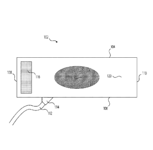
FIG. 1 shows a front surface 102 of a pressure cuff 120 in accordance with one
embodiment of the invention. The pressure cuff 120 has an inflatable air
bladder (not shown)
linked via a connection member 114 to an inflation tube 112 that is attached
to a monitor
device (not shown) capable of inflating the bladder.
The pressure cuff 120 comprising an essentially rectangular tube of material
having an
upper edge 104, lower edge 106, first side 108 and second side 110. A hook and
loop fastener
116 is positioned at the first side 108 and a decorative element 118 may be
attached to the front
surface 102. The decorative element 118 may be selected from the group
including, but not
limited to: a word; a phrase; a symbol; an image; studs; choking hand image;
advertisements,
etc.
The decorative element 118 or decorative elements 118 may be printed onto the
front
surface 102, of the pressure cuff 120 or they may be stitched or embroidered,
or they may be
attached by way of releasable fasteners such a snaps, poppers or hook and loop
fasteners such
as Velcro'. When the decorative element 118 or decorative elements 118 are
attached by way
of releasable fasteners, a variety of different decorative element 118 or
decorative elements 118
may be used interchangeably by the participant, such as "branded" compatible
patches,
8
Date Recue/Date Received 2021-06-25
Docket No. 0184-222CAPT
PATENT
nameplates, unique colors, unique textures, etc., that are actually designed
as attachments for
this device only. The actual size of the decorative element 118 or decorative
elements 118 can
be of various shapes and sizes.
Certain embodiments of the invention may include selection of customized
"sleeves"
that would slide over top of the entire pressure cuff 120 thereby providing
additional options
for customized exterior colors, fabrics, and textures.
The front surface 102 of the pressure cuff 120 may be fabricated from a
variety of
materials selected from the group including, but not limited to: silk; satin;
cotton; and
polyester. The basic, non-sleeve version the front surface 102 of the pressure
cuff 120 would be
.. made from the same material the basic cuff would be made out of. In the
embodiment that
features customizable separate sleeves, the front surface 102 could comprise
customized
exterior colors, fabrics, and textures.
FIG. 2 shows a rear surface 202 of the pressure cuff 120 in accordance with
one
embodiment of the invention. Again, the inflatable air bladder, situated
between the front
surface 102 of the pressure cuff 120 and the rear surface 202 of the pressure
cuff 120 is not
shown. The connection member 114 and inflation tube 112 that are respectively
attached to the
inflatable air bladder and monitor device (not shown) can be seen.
The rear surface 202 of the pressure cuff 120 has an upper edge 104, lower
edge 106,
first side 108 and second side 110 corresponding to the upper edge 104, lower
edge 106, first
.. side 108 and second side 110 illustrated in FIG. 1. An additional piece of
hook and loop
fastener 116, such as Velcro'TM, is positioned at the second side 110 of the
rear surface 202 that
cooperates with the hook and loop fastener 116 attached to the first side 108
of the front
surface 102.
The rear surface 202 may be fabricated from a variety of materials selected
from the
.. group including, but not limited to: silk; satin; cotton; and polyester.
The basic, non-sleeve
version the rear surface 202 would be made from the same material the basic
cuff would be
made out of. In the embodiment that features customizable separate sleeves,
the rear surface
202 could comprise customized interior colors, fabrics, and textures.
FIG. 3 shows a front surface 102 view of the pressure cuff 120 in accordance
with one
embodiment of the invention. The aspects illustrated in FIG. 1 can be seen, in
addition to
embellishments 302. In this instant the embellishments 302 are shown as studs.
Various other
9
Date Recue/Date Received 2021-06-25
Docket No. 0184-222CAPT
PATENT
individual embellishments 302 can be attached to the front surface 102 by, for
example, gluing,
sewing and riveting. Alternative embodiments of the invention may have studs
on the interior
of rear surface 202 of the pressure cuff 120 so the cuff squeezes the studs
into the neck for
additional pleasure/pain.
FIG. 4 shows a rear surface 202 view of the pressure cuff 120 in accordance
with one
embodiment of the invention. The aspects illustrated in FIG. 2 can be seen, in
addition to a pair
of rails 402.
Typically, the rail 402 or rails 402 additionally comprise an end stop 404.
The rail 402
or rails 402 are situated on the rear surface 202 of the pressure cuff 120,
and extend from the
first side 108 of the pressure cuff 120 to the second side 110 of the pressure
cuff 120. In the
embodiment of the invention illustrated in this figure, two rails 402 with end
stops 404 can be
seen extending from the first side 108 to the second side 110 of the pressure
cuff 120.
The rail 402 or rails 402 may be made of plastic that may be molded, extruded
or 3D
printed.
FIG. 5 shows a rear surface 202 view of the pressure cuff 120 in accordance
with one
embodiment of the invention. The aspects illustrated in FIG. 4 can be seen, in
addition to two
differently shaped pressure enhancement members 502.
Again, the rail 402 or rails 402 additionally comprise an end stop 404. The
rail 402 or
rails 402 are situated on the rear surface 202 of the pressure cuff 120, and
extend from the first
side 108 of the pressure cuff 120 to the second side 110 of the pressure cuff
120. In the
embodiment of the invention illustrated in this figure, two rails 402 with end
stops 404 can be
seen extending from the first side 108 to the second side 110 of the pressure
cuff 120.
The pressure enhancement members 502 may be oval or circular in shape and have
a rail
engagement member 504 or rail engagement members 504 attached in a position or
positions
such that they cooperate with the rail 402 or rails 402. Various different
shaped and sized
pressure enhancement members 502 are considered to be within the scope of
protection sought.
The purpose of the pressure enhancement members 502 is order to customize the
participant's
experience. The pressure enhancement members 502 add extra pressure on
arteries in neck. The
plastic rail 402 or rails 402 allow attachments, such as the pressure
enhancement members 502
illustrated in this figure, to slide on easily the rail 402 or rails 402 and
be appropriately
positioned on the neck of the participant.
Date Recue/Date Received 2021-06-25
Docket No. 0184-222CAPT
PATENT
Attachments will slide into the rails that are already attached to the cuff
upon purchase.
If a user buys a custom attachment (studs, pressure balls, etc.) simply slide
the basic interior
piece off, exposing the rails, then slide the attachment on, which would look
like the basic
interior sleeve with an attachment on it. No rails visible.
FIG. 6 shows a rear surface 202 view of the pressure cuff 120 in accordance
with one
embodiment of the invention. The aspects illustrated in FIG. 5 can again be
seen. In this figure,
the pressure enhancement members 502 can be seen installed at appropriate
positions on the
rails 402. The pressure enhancement members 502 may be made of plastic that is
molded,
extruded or 3D printed.
FIG. 7 shows a rear surface 202 view of the pressure cuff 120 in accordance
with one
embodiment of the invention. The aspects illustrated in FIG. 6 can again be
seen. In this figure
however, only one rail 402 is present. The rail 402 again extends from the
first side 108 of the
pressure cuff 120 to the second side 110 and has an end stop 404 installed. It
of positioned
essentially mid-way between the upper edge 104 and the lower edge 106 of the
pressure cuff
120. The pressure enhancement members 502 can be seen installed at appropriate
positions on
the rail 402.
FIG. 8 shows a typical combination pump and monitor unit 802. The combination
pump
and monitor unit 802 features a display screen 804 and a series of control
buttons 806.
The recommended mode of operation would have the participant apply the
pressure cuff
120 at default setting to fit snugly around the neck, but not impede the on
flow of blood. The
participant would set a particular time setting to maintain the pressure cuff
120 at the inflated
setting. A safe maximum time period is pre-programmed into the combination
pump and
monitor unit 802.
The participant can then use one of the control buttons 806 to inflate air
bladder inside
the pressure cuff 120 to pre-selected level of pressure for the pre-selected
time period. The
combination pump and monitor unit 802 is pre-programmed so as not to exceed a
previously
determined safe maximum time limit. From the moment the cuff has been inflated
to desired
pressure setting, the control mechanism, should remain at that pressure
setting for the
participant's desired time option.
When the time is approaching for the pressure cuff 120 to deflate, a
'countdown to zero
pressure' indicator will be deployed and the combination pump and monitor unit
802 will give
11
Date Recue/Date Received 2021-06-25
Docket No. 0184-222CAPT
PATENT
a visual, light or sound indication. If the participant does not want the
countdown to begin, they
can re-engage the controls and an additional pre-determined time option will
start commence,
up to the previously determined safe maximum time limit. Typically, the
second, and
subsequent, re-engagement of the controls would provide a shorter inflated
time interval that
the previous engagement/re-engagement period.
The participant will be able to start the time option over at any time prior
to the official
countdown beginning. Similarly, they will be able to deflate pressure cuff 120
to zero pressure
at any time. The countdown to deflation will only start if the participant has
not engaged any of
the override options to either extend the inflation period, or to prematurely
deflate the pressure
.. cuff 120. As long as the participant is not incapacitated, they can control
what happens and for
how long through the display screen 804 and pre-programmed control panel.
However, if the
participant becomes incapacitated and is unable to operate the safety deflate
control button 806,
the pressure cuff 120 will automatically deflate to zero pressure within the
predetermined time
period, before serious injury has occurred. Hence the participant can safely
engage in autoerotic
asphyxiation without risking injury or death.
FIGS. 9A and 9B show in details of the connection mechanism of the pressure
enhancement members 502 to the rails 402 (not shown).
FIG. 9A illustrates generally a pressure enhancement member 502 that is for
connection
to the pressure cuff 120 (not shown) by way of rail engagement members 504. In
this
embodiment, the rail engagement members 504 are in a male orientation.
FIG. 9B illustrates generally a pressure enhancement member 502 that is for
connection
to the pressure cuff 120 (not shown) by way of rail engagement members 504. In
this
embodiment, the rail engagement members 504 are in a female orientation.
FIGS. 10A and 10B show in details of the connection mechanism of the rails 402
to the
pressure enhancement members 502 (not shown).
FIG. 10A illustrates generally two rails 402 each having a pressure
enhancement
engagement member 1002 that is for connection to the pressure enhancement
member 502 (not
shown). In this embodiment, the pressure enhancement engagement members 1002
are in a
female orientation.
FIG. 10B illustrates generally two rails 402 each having a pressure
enhancement
engagement member 1002 that is for connection to the pressure enhancement
member 502 (not
12
Date Recue/Date Received 2021-06-25
Docket No. 0184-222CAPT
PATENT
shown). In this embodiment, the pressure enhancement engagement members 1002
are in a
male orientation.
FIG. 11 shows a molded choking hand simulator 1102 that can be mounted on
rails 402
(not shown) the inside of a pressure cuff 120 (also not shown). The molded
choking hand
simulator 1102 can be made from various different materials that are flexible
such as silicone
or rubber. The pressure enhancement member 502 that has the hand shaped
attachment fitted to
the one or more rails 402 that would simulate the feeling of being choked by a
partner hand.
This attachment would be important if audio were to be added to devices.
Having the unit say
something about choking you and then having the sensation of a real hand would
be important
to many users.
FIG. 12 shows an embodiment of a sleeve embodiment of the invention. The
sleeve
1202 is configured as a tube of material the with two open ends.
The sleeve 1202 can be slide over the basic pressure cuff 120, that does not
have one or
more rails 402 or pressure enhancement members 502. In this instance, the
sleeve 1202 could
provide a variety of different customized exterior colors, fabrics, and
textures. In some
instances, studs may be present on a surface of the sleeve, to provide
optional add-on features
for the user.
In an alternative embodiment of the invention, the sleeve 1202 can be slide
over the
pressure cuff 120, and any pressure enhancement member 502 that is present.
The customizable
sleeve when slid over the pressure cuff 120, rails 402, and pressure
enhancement members 502
may provide a more comfortable feel to the user. A great deal of pressure will
be pushing
against the neck of the user and exposed rails could cause discomfort to users
who aren't
looking for a pain aspect.
Embodiments of the invention may include commercial kits comprising the
pressure
cuff 120, combination pump and monitor unit 802, and one or more
interchangeable sleeves
1202. In some embodiments, the pressure cuff 120 may also be fitted with rails
402 and one or
more pressure enhancement members 502.
As described and illustrated above, numerous embodiments of the invention are
contemplated to fall within the scope of protection being sought.
Humans will always engage in high-risk behavior and participants can engage in
autoerotic asphyxiation using the disclosed pressure cuff 120 and combination
pump and
13
Date Recue/Date Received 2021-06-25
Docket No. 0184-222CAPT
PATENT
monitor unit 802 without accidentally suffocating to death. The timed pressure
safety release
function, or Dead man's switch, provides the safety aspects to allow
participants to engage in
AEA.
The design of the pressure cuff 120 is sleek, comfortable and adjustable and
available in
different sizes. The pressure cuff 120 can be fabricated in various colors and
textures could be
specifically customizable by the participant. Different internal attachments
can be added by the
participant. The attachments can be of any shape and size. They can be smooth
or studded.
They can be like the oval or round ball attachments illustrated in FIGS. 5, 6
and 7 as pressure
enhancement members 502. Alternatively, they can mimic a choking hand by way
of a hand-
shaped simulator attachment illustrated in FIG. 11
The combination pump and monitor unit 802 is part of the device is of the type
known
to those of skill in the field. The technology resembles the monitor/pump
device employed to
inflate blood pressure cuffs except that it is modified to allow the pressure
cuff 120 to remain
inflated beyond an initial pre-determined time period and incorporates the
manual and
automatic deflation safety over-ride options. The combination pump and monitor
unit 802
typically has a USB charger port.
The pressure cuff 120 and combination pump and monitor unit 802 can
additionally be
linked to a variety of hands-free devices, such as Sin i and Alexa. These Safe-
Phyx' devices
will allow participants to speak to the device to start or stop inflation.
This feature will benefit
visually impaired participants. Some participants may enjoy having the device
speak to them.
Certain may enhance the experience. Certain embodiments could feature the
voices of popular
actors or actresses. The pressure cuff 120 and combination pump and monitor
unit 802 can also
be controlled via cell phones, mobile devices, Bluetooth connections or other
apps.
In some embodiments of the invention, the pressure cuff 120 has built-in
optical sensors
to provide the combination pump and monitor unit 802 with information relating
to the
participants current physiological condition and any pertinent changes in
their physiology.
There are several ways to measure and analyze blood flow. Photoplethysmography
(PPG) is a
non-invasive and simple technique that accesses capillaries using differential
light absorption
characteristics and an optical sensor. PPG detects changes in the pulse waves
generated by
blood flow through the microcirculation. When optical sensors are present in
the pressure cuff
120 immediate feedback to the participant concerning their current
physiological condition and
14
Date Recue/Date Received 2021-06-25
Docket No. 0184-222CAPT
PATENT
any pertinent changes in their physiology, including hypoxia, hypercarbia and
alkalosis, can be
provided. Again, certain ranges for specific criteria can be pre-programmed
into the
combination pump and monitor unit 802, and when these ranges are exceeded, the
pressure cuff
120 can be prematurely deflated.
The pressure cuff 120 and combination pump and monitor unit 802 could
optionally be
further customized via connection to linked VR compatibilities connecting the
device to a
virtual reality headset. This combination could provide participants with the
ultimate
experience, allowing them to be immersed in any environment of their choosing,
including
being able to see the person or thing choking them. The devices would pair and
allow a pre-
recorded experience all while still having easy access to the safety controls.
The combination pump and monitor unit 802 is able to control other attachments
in
place of the neck cuff. For example, an additional embodiment of the invention
relates to the
attachment of an inflatable cock ring attachment in place of the pressure cuff
120. The
attachment of controllable, inflatable cock rings can be used to increase
sexual pleasure for
men.
The foregoing descriptions of specific embodiments of the present invention
have been
presented for purposes of illustration and description. They are not intended
to be exhaustive or
to limit the invention and method of use to the precise forms disclosed. Many
modifications
and variations are possible in light of the above teaching. The embodiments
described were
chosen and described in order to best explain the principles of the invention
and its practical
application, and to thereby enable others skilled in the art to best utilize
the invention and
various embodiments with various modifications as are suited to the particular
use
contemplated. It is understood that various omissions or substitutions of
equivalents are
contemplated as circumstance may suggest or render expedient, but is intended
to cover the
application or implementation without departing from the spirit or scope of
the claims of the
present invention.
Date Recue/Date Received 2021-06-25