Note: Descriptions are shown in the official language in which they were submitted.
88728148
SYSTEMS AND METHODS FOR RADIOTHERAPY WITH MAGNETIC
RESONANCE IMAGING
[0001] This application is a divisional of Canadian Patent Application No.
2,904,603,
filed on March 11, 2014.
TECHNICAL FIELD
[0002] The present disclosure relates to systems and methods for the delivery
of
radiotherapy in conjunction with magnetic resonance imaging.
BACKGROUND
[0003] It is desirable to combine radiation therapy with repetitive real-time
imaging
using a magnetic resonance imaging system (MRI) in order to better locate and
treat therapy
targets while sparing nearby healthy tissue. While MRIs and radiation
treatment systems such
as linear accelerators or radioisotope beams have operated separately from one
another for
quite some time, combining the two technologies presents many significant
technological
challenges. Examples of such challenges include the magnetic fields and eddy
currents
generated in ferromagnetic and conductive radiotherapy equipment through the
MRI's main
and gradient magnets, both of which can destroy an MRI's ability to provide
quality images.
1
Date Recue/Date Received 2021-07-07
88728148
SUMMARY
100041 Disclosed herein are systems and methods for combining
radiotherapy
with magnetic resonance imaging.
[0005] In one embodiment, a system may include a magnetic
resonance
imaging system, a gantry, one or more radiation therapy heads fixed to the
gantry, one or
more collimating devices associated with the one or more heads, including a
plurality of
leaves, one or more leaf drive motors for moving the leaves, the one or more
leaf drive
motors including one or more position sensors, and a magnetic shield
substantially
surrounding the one or more position sensors, one or more permanent magnets
adjacent
the one or more leaf drive motors, the one or more permanent magnets oriented
so as to
counteract the MRI's main magnetic field, and one or more additional
conductive
elements disposed around the gantry in a substantially symmetrical manner. The
one or
more additional conductive elements may have a shape, volume or material
permeability
designed to substantially match the shape, volume or material permeability of
the
collimating devices. In addition, the one or more additional conductive
elements may be
substantially similar to the outer housings of the collimating devices. In one
embodiment, only one radiation therapy head is fixed to the gantry and only
one
collimating device is associated with the one radiation therapy head and the
one or more
additional conductive elements is a single conductive element extending
substantially
around the portion of the gantry not occupied by the one collimating device.
Furthermore, the magnetic shield may be made of steel and may be cylindrical
in shape.
[0006] In another embodiment, a system may include a magnetic
resonance
imaging system, a gantry, one or more radiation therapy heads fixed to the
gantry, one or
2
Date Recue/Date Received 2021-07-07
88728148
more collimating devices associated with the one or more heads and one or more
additional conductive elements disposed around the gantry in a substantially
symmetrical
manner. The one or more additional conductive elements may be additional
collimating
devices or may be substantially similar to the outer housings of the
collimating devices.
In addition, the one or more additional conductive elements may have a shape,
volume or
material permeability designed to substantially match the shape, volume or
material
permeability of the collimating devices. In another embodiment, the one or
more
radiation therapy heads may be three radioisotopic sources, and the one or
more
additional conductive elements may be three conductors substantially similar
to the outer
housings of the collimating devices. In yet another embodiment, only one
radiation
therapy head is fixed to the gantry and only one collimating device is
associated with the
one radiation therapy head and the one or more additional conductive elements
comprises
a single conductive element extending substantially around the portion of the
gantry not
occupied by the one collimating device.
[0007] In still another embodiment, the system may include a
magnetic
resonance imaging system, a gantry, one or more radiation therapy heads fixed
to the
gantry, one or more collimating devices associated with the one or more heads,
including
a plurality of leaves, one or more leaf drive motors for moving the leaves,
the one or
more leaf drive motors including one or more position sensors and a magnetic
shield
substantially surrounding the one or more position sensors. The magnetic
shield may
have a cylindrical shape and may be made out of ferromagnetic material, such
as steel.
[00081 In another embodiment, the system may include a magnetic
resonance
imaging system, a gantry, one or more radiation therapy heads fixed to the
gantry, one or
3
Date Recue/Date Received 2021-07-07
88728148
more collimating devices associated with the one or more heads, including a
plurality of
leaves, one or more leaf drive motors for moving the leaves and one or more
permanent
magnets adjacent the one or more leaf drive motors, the one or more permanent
magnets
oriented so as to counteract the MRI's main magnetic field. Permanent magnets
may be placed
on either side of the one or more leaf drive motors and may be made from
Neodymium.
[0008a] According to one aspect of the present invention, there is provided a
system
comprising: a magnetic resonance imaging system; a gantry; one or more
radiation therapy
heads fixed to the gantry; one or more collimating devices associated with the
one or more
heads, including a plurality of leaves; one or more leaf drive motors for
moving the leaves, the
one or more leaf drive motors including one or more position sensors and a
magnetic shield
substantially surrounding the one or more position sensors.
10008b] According to another aspect of the present invention, there is
provided a
system for delivery of radiotherapy in conjunction with magnetic resonance
imaging, the
system comprising: a magnetic resonance imaging system; a gantry; a radiation
therapy head
fixed to the gantry; a collimating device associated with the radiation
therapy head, including
a plurality of leaves; a leaf drive motor for moving a leaf, the leaf drive
motor including a
position sensor and a magnetic shield substantially surrounding the position
sensor.
[0008c] According to still another aspect of the present invention, there is
provided a
system comprising: a magnetic resonance imaging system; a gantry; a radiation
therapy head
fixed to the gantry; a collimating device associated with the radiation
therapy head, the
collimating device comprising: a plurality of leaves and a corresponding
plurality of leaf drive
motors; and a position sensor for each of the plurality of leaves, the
position sensor configured
to determine a position of a corresponding leaf; and a magnetic shield
substantially
surrounding each position sensor.
[0009] These and other features, aspects, and advantages of the present
disclosure will
become better understood with reference to the following description and
claims.
4
Date Recue/Date Received 2021-07-07
88728148
BRIEF DESCRIPTION OF DRAWINGS
[0010] Features, aspects, and implementations of the disclosure are described
in
conjunction with the attached drawings, in which:
[0011] FIG. 1 is a simplified diagram illustrating aspects of a radiation
therapy device
operating in conjunction with a magnetic resonance imaging system consistent
with
implementations of the current subject matter;
[0012] FIG. 2 is a simplified diagram illustrating an example of a treatment
system
consistent with implementations of the current subject matter;
[0013] FIG. 3 illustrates an exemplary collimating device, specifically a
multi-leaf
collimator;
[0014] FIG. 4 illustrates one example of an arrangement of conductive elements
consistent with implementations of the current subject matter;
4a
Date Recue/Date Received 2021-07-07
88728148
[0015] FIG. 5A is a simplified diagram illustrating a leaf motor
combined
with an example magnetic shield consistent with implementations of the current
subject
matter;
[0016] FIG. 5B is a simplified representation of the effect of a
magnetic
shield on an MRI's main magnetic field;
[0017] FIG. 6 is a simplified illustration of permanent magnets
being placed
adjacent a bank of leaf motors consistent with implementations of the current
subject
matter;
[0018] FIG. 7 illustrates an exemplary magnetic orientation of
permanent
magnets with respect to an MRI's main magnetic field consistent with
implementations of
the current subject matter; and
[0019] FIG. 8 shows a process flow chart illustrating features of
a method
consistent with implementations of the current subject matter.
DETAILED DESCRIPTION
[0020] Disclosed herein are systems and methods for combining
radiotherapy
with magnetic resonance imaging. FIG. 1 is a simplified schematic view of an
implementation of a radiation therapy system including a radiation therapy
bead 104
mounted on a gantry 106, which can rotate to different positions to enable
radiation
delivery from different angles. The exemplary system depicted in FIG. 1 also
includes an
MRI 102, which may be used for real-time imaging during radiation therapy and
maybe
of the split or open type of MRI as shown. Radiation therapy head 104 can be
used to
direct a treatment beam at a target within patient 108 lying on couch 110.
Date Recue/Date Received 2021-07-07
88728148
[0021] FIG. 2 depicts an example of a radiation therapy system
that may be
used with the disclosed systems and methods. The example depicted includes
three
radioisotopic sources 200, such as Cobalt-60, mounted on gantry 106, directing
three
radiotherapy beams at patient 108. While this example utilizes radioisotopic
beams, this
disclosure contemplates and is applicable to other radiotherapy beam types
such as linear
accelerators, proton beams, etc. In addition, while the example of FIG. 2
shows three
radiotherapy heads spaced in an equidistant manner around the gantry, the
systems and
methods disclosed herein apply to any number of radiotherapy heads (i.e., one
or more).
[0022] FIG. 2 also depicts collimating devices 202 attached to
gantry 106 and
associated with each of the sources 200. Collimating devices 202 may, for
example, be
multi-leaf collimators (MLCs), as shown in further detail in FIG. 3. MLCs
typically have
two banks of opposing pairs of leaves 302, which move independently and can
open to
form apertures of various shapes and sizes. The number of leaves 302 can vary.
Leaves
302 may be made of tungsten or any suitable material or materials for blocking
radiation.
MLCs may also employ a tongue and groove arrangement on the long sides and
front of
the leaves 302 to limit interleaf radiation leakage and can be configured for
inter-
digitation of the leaves 302 in the closed position.
[0023] Each leaf 302 of each bank of leaves may be capable of
independent
motion and may be driven by leaf motors 304 through connecting rods 306. An
MLC
control system can control the two opposing banks of leaves 302 to
independently
position the edge of each leaf 302 to a specified location in order to block a
radiation
beam and form a field size of a specific shape.
6
Date Recue/Date Received 2021-07-07
88728148
[0024] The MLC leaves 302, motors 304, and other components may be
supported by housing 308 that then attaches to gantry 106. Housing 308 may be,
for
example, made from aluminum.
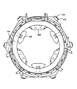
[00251 FIG. 4 depicts an exemplary gantry 106 layout for the
example
radiation therapy system depicted in FIG. 2 having three radioisotopic sources
200 along
with three corresponding collimating devices 202. The embodiment of FIG. 4
further
includes additional conductive elements 400. Conductive elements 400 may be
made of
a single material or combine multiple materials. The conductive elements
preferably
have a shape, volume and material permeability (i.e., the degree of
magnetization that a
material obtains in response to an applied magnetic field) designed to
substantially match
those of collimating devices 202 in such respects as are pertinent to the
generation of
eddy currents during energizing of the MRI's gradient coils. For example, in
the
embodiment depicted in FIG. 4, conductive elements 400 could comprise
identical multi-
leaf collimators.
[0026] Because including additional sets of identical multi-leaf
collimators
would be expensive, and because eddy currents are primarily generated in the
outer
housings 308 of collimating devices 202, conductive elements 400 may merely be
substantially similar to the housings 308 of collimating devices 202. For
example,
conductive elements 400 may be pairs of aluminum multi-leaf collimator
housings.
Alternatively, conductive elements 400 may be other shapes or other materials
that
substantially mimic the eddy current properties of the collimating devices 202
or
housings 308.
7
Date Recue/Date Received 2021-07-07
88728148
[0027] Conductive elements 400 are preferably placed in positions
around
gantry 106 to create a substantially symmetrical pattern, as depicted in FIG.
4. The
positions and number of conductive elements 400 may vary, but the resulting
arrangement is preferably symmetrical about the circumference of gantry 106.
As noted
above, this disclosure contemplates and is applicable to any type of
radiotherapy device.
In the case where there is a single radiation therapy head, for example, a
linear
accelerator, the same principles for the additional conductive elements 400
described
above apply. In one example, there may be five conductive elements 400
substantially
equally spaced around gantry 106, along with the single collimating device
202. In
another example, a single conductive element 400 may extend around
substantially the
entire portion of the circumference of gantry 106 not occupied by collimating
device 202.
While a number of examples have been given for the design and layout of
conductive
elements 400, any design and layout meeting the spirit of this disclosure is
contemplated.
[0028] Leaf motors 304 associated with collimating devices 202,
typically
include one or more position sensors 500 capable of determining the position
of
associated leaves 302, as shown in FIG. 5A. For example, position sensor 500
may be a
Hall effect encoder, which is capable of determining how many times a motor
has
rotated. A preferred embodiment includes magnetic shields 502 substantially
surrounding sensors 500. Magnetic shield 502 is preferably cylindrically
shaped and
made of a ferromagnetic material, in one example. One such ferromagnetic
material may
be steel, but other materials and shapes suitable for magnetic shielding can
be used. In
one embodiment, the wall thickness of a steel cylinder is in the range of 1.5-
2.0 mm and
reduces the magnetic field within the shield to below 140 Gauss. In one
preferred
8
Date Recue/Date Received 2021-07-07
88728148
embodiment, the wall thickness of the steel cylinders 1.6 mm. FIG. 5B
demonstrates
how magnetic shield 502 can decrease the magnetic field to which sensor 500 is
subjected from that of the main magnet magnetic field 504 to a reduced
magnetic field
506 observed within the shield.
[0029] Position sensors 500 are preferably oriented within
magnetic shield
502 so as to be in the location at which the magnetic field is weakest, as
shown in FIG.
5B as the top and bottom of magnetic shield 502.
[0030] In one embodiment of the disclosure, permanent magnets 600
may be
placed adjacent to the bank of motors 304, as shown in FIG. 6. Permanent
magnets 600
may be held in place by housings 402 and, in one embodiment, may be made from
Neodymium (NdFeB). The polar orientation of the permanent magnets 600 should
be
such that it counteracis the NMI's main magnetic field and the magnetic field
induced in
the motors and motor shields 304. FIG. 7 illustrates this orientation of
permanent
magnets 600 amidst the MRI's main magnetic field 700, showing the north-south
polarity
of permanent magnets 702 opposing the main magnet's magnetic field 700.
[0031] One embodiment of the disclosure contemplates one permanent
magnet being placed on either side of the bank of motors 304 as shown in FIG.
6.
However, any number and arrangement of properly oriented permanent magnets 600
may
be used that results in substantial cancellation of the magnetic field induced
in motor
shields 304 and other ferromagnetic materials in the area (for example, the
motor
housings). As an alternative to permanent magnets 600, active windings could
be used as
well. The canceling effect of the magnet design's strengths, field
orientations, and
locations can be determined utilizing modeling software such as FARADAY,
available
9
Date Recue/Date Received 2021-07-07
88728148
from Integrated Engineering Software, or any other appropriate software such
as
VectorField, for example, and with further analysis of results potentially
being performed
in a program such as MATLAB or any other appropriate software such as FORTRAN,
for example.
[00321 In one embodiment of the systems and methods of the
disclosure, the
leaf motors 304 may also be oriented so that the permanent magnets stators
within them
either canceLout the group of motors' magnetic field, or may alternatively be
oriented in
a manner that causes the group's magnetic field to be known or predictable.
[0033] While placing permanent magnets 600 adjacent the banks of
leaf
motors 304 substantially improves field homogeneity, the main magnetic field
can be
further improved, and the effect of radiation therapy equipment on MRI 102
further
decreased. In addition to the leaf motors 304, magnetic shields 502, motor
housings,
stators within the motors and the like, the collimating devices 202 contain
leaves 302 that
may also have ferromagnetic properties. For example, leaves 302 may be made
from a
material such as tungsten, which has a relatively low permeability of
approximately 1.03,
but which, due to the large volume of the leaves, may also have a significant
effect on the
MRrs magnetic field. Magnetic field homogeneity may be in further improved,
for
example, by placing additional permanent magnet shims within the system. For
example,
in the embodiment depicted in FIG. 4 and discussed above, additional permanent
magnets
may be placed on the three conductive elements 400. While such location has
proven
beneficial for this embodiment, there are numerous other locations that would
prove
beneficial to field homogeneity, as can be determined using modeling software
such as
FARADAY or any other appropriate software such as VectorField, for example.
Other
Date Recue/Date Received 2021-07-07
88728148
locations could include, for example, on the collimating devices 202
themselves. In
addition, active windings could be used in place of, or in conjunction with,
the permanent
magnets. Finally, standard ferromagnetic shims may be used.
[0034] FIG. 8 shows a process flow chart 800 illustrating features
of a method
consistent with implementations of the current subject matter. At 802, images
of a
subject are captured using a magnetic resonance imaging system. At least one
radiation
beam is delivered to the subject from one or more radiation therapy heads
fixed to a
gantry at 804. A radiation delivery field size of a specific shape if formed
at 806 by
partially blocking the radiation beam with a collimating device. The
collimating device
includes a position sensor and a motor. The position sensor determines how
many times
the motor is rotated. The method can optionally include either or both of
counteracting a
magnetic field to which the position sensor is subjected at 810 and mimicking
an eddy
current property of at least one of the collimating device and a housing of
the collimating
device at 812. The counteracting of the magnetic field can include shielding
the position
sensor with a magnetic shield to achieve a reduced magnetic field relative a
main magnet
magnetic field of the magnetic resonance imaging system. The mimicking of the
eddy
current can include disposing additional conductive elements symmetrically
about the
gantry.
[0035] The subject matter described herein can be embodied in
systems,
apparatus, methods, and/or articles depending on the desired configuration.
The
implementations set forth in the foregoing description do not represent all
implementations consistent with the subject matter described herein. Instead,
they are
merely some examples consistent with aspects related to the described subject
matter.
11
Date Recue/Date Received 2021-07-07
88728148
While various implementations in accordance with the disclosed principles have
been
described above, it should be understood that they have been presented by way
of
example only, and are not limiting. Thus, the breadth and scope of the
invention(s)
should not be limited by any of the above-described exemplary implementations,
but
should be defined only in accordance with the claims and their equivalents
issuing from
this disclosure. The present disclosure contemplates that the calculations
disclosed in the
implementations herein may be performed in a number of ways, applying the same
concepts taught herein, and that such calculations are equivalent to the
implementations
disclosed. Furthermore, the above described advantages are not intended to
limit the
application of any issued claims to processes and structures accomplishing any
or all of
the advantages.
[00361 Additionally, section headings shall not limit or
characterize the
invention(s) set out in any claims that may issue from this disclosure.
Specifically, and
by way of example, although the headings refer to a "Technical Field," such
claims
should not be limited by the language chosen under this heading to describe
the so-called
technical field. Further, the description of a technology in the "Background"
is not to be
construed as an admission that technology is prior art to any invention(s) in
this
disclosure. Neither is the "Summary" to be considered as a characterization of
the
invention(s) set forth in issued claims. Furthermore, any reference to this
disclosure in
general or use of the word "invention" in the singular is not intended to
imply any
limitation on the scope of the claims set forth below. Multiple inventions may
be set
forth according to the limitations of the multiple claims issuing from this
disclosure, and
12
Date Recue/Date Received 2021-07-07
88728148
such claims accordingly define the invention(s), and their equivalents, that
are protected
thereby.
[0037] Although a few variations have been described in detail
above, other
modifications or additions are possible. In particular, further features
and/or variations
can be provided in addition to those set forth herein. For example, the
implementations
described above can be directed to various combinations and subcombinations of
the
disclosed features and/or combinations and subcombinations of several further
features
disclosed above. In addition, the logic flows depicted in the accompanying
figures and/or
described herein do not necessarily require the particular order shown, or
sequential
order, to achieve desirable results.
[0038] In the descriptions above and in the claims, phrases such
as "at least
one of" or "one or more of' may occur followed by a conjunctive list of
elements or
features. The term "and/or" may also occur in a list of two or more elements
or features.
Unless otherwise implicitly or explicitly contradicted by the context in which
it used,
such a phrase is intended to mean any of the listed elements or features
individually or
any of the recited elements or features in combination with any of the other
recited
elements or features. For example, the phrases "at least one of A and B;" "one
or more of
A and B;" and "A and/or B" are each intended to mean "A alone, B alone, or A
and B
together." A similar interpretation is also intended for lists including three
or more items.
For example, the phrases "at least one of A, B, and C;" "one or more of A, B,
and C;"
and "A, B, and/or C" are each intended to mean "A alone, B alone, C alone, A
and B
together, A and C together, B and C together, or A and B and C together."
13
Date Recue/Date Received 2021-07-07
88728148
[0039] Use of the
term "based on," above and in the claims is intended to
mean, "based at least in part on," such that an unrecited feature or element
is also
permissible.
14
Date Recue/Date Received 2021-07-07