Note: Descriptions are shown in the official language in which they were submitted.
CA 03124652 2021-06-21
WO 2020/139780 PCT/US2019/068048
SYSTEMS AND METHODS FOR ELECTRICAL POWER GENERATION
CROSS-REFERENCE TO RELATED APPLICATIONS
[0001] This application claims benefit of U.S. provisional patent application
Serial No.
62/785,538 filed December 27, 2018, and entitled "Systems And Methods For
Electrical
Power Generation," which is hereby incorporated herein by reference in its
entirety.
STATEMENT REGARDING FEDERALLY SPONSORED
RESEARCH OR DEVELOPMENT
[0002] Not applicable.
BACKGROUND
[0003] This disclosure generally relates to electrical power generation. More
particularly,
some embodiments of this disclosure relate to systems and methods for
generating
electrical power utilizing geothermal energy accessed from a bore extending
from the
surface into a subterranean formation.
[0004] Bore holes are commonly drilled from the surface to access minerals or
other
resources (e.g., oil, gas, water, etc.) that exist within subterranean
formations. The
internal heat of the Earth (e.g., residual heat from the Earth's formation,
heat generated
by radioactive elements beneath the Earth's surface, etc.) typically induces
an increasing
temperature gradient per increasing depth within such bore holes (e.g., at a
rate of
approximately 1 F per 70 vertical feet in some locations). The elevated
temperatures
within these bore holes are potential sources of energy that may be harnessed
to provide
power (e.g., electrical power) at the surface.
BRIEF SUMMARY OF THE DISCLOSURE
[0005] Some embodiments disclosed herein are directed to a system including a
power
generation assembly. The power generator assembly is configured to be enclosed
within
a wellbore extending from the surface into a subterranean formation along a
central axis.
Wherein the power generation assembly includes a thermoelectric generator, and
a
conductor configured to conduct electricity generated by the thermoelectric
generator to
1
CA 03124652 2021-06-21
WO 2020/139780 PCT/US2019/068048
the surface. The power generation assembly is configured to circulate a
working fluid
through a closed loop in the power generation assembly in response to the
receipt of
geothermal energy within the subterranean formation, to cause the
thermoelectric
generator to generate electricity.
[0006] Other embodiments disclosed herein include a power generation assembly.
In an
embodiment, the power generation assembly includes a first barrier and a
second barrier
spaced from one another along a central axis. In addition, the power
generation
assembly includes a first chamber, a second chamber, and a third chamber. The
first
chamber, the second chamber, and the third chamber are bounded by the first
barrier and
the second barrier, and the second chamber is axially disposed between the
first barrier
and the second barrier. Further, the power generation assembly includes a
central
housing defining a central throughbore and an annular flow path in the second
chamber.
Still further, the power generation assembly includes a thermoelectric
generator disposed
within the second chamber radially between the central throughbore and the
annular flow
path, and a working fluid disposed in each of the first chamber, the second
chamber, and
the third chamber. The central throughbore and the annular flow path are in
fluid
communication with the first chamber and the third chamber. When the first
chamber is
exposed to a first temperature and the second chamber is exposed to a second
temperature that is higher than the first temperature the working fluid flows
through the
central throughbore at a third temperature and flows through the annular flow
path at a
fourth temperature that is less than the third temperature.
[0007] Still other embodiments are directed to a method of generating
electrical power.
In an embodiment, the method includes (a) positioning a power generation
assembly in a
wellbore extending into a subterranean formation, and (b) transferring heat
from the
formation into a working fluid disposed within the power generation assembly.
In addition,
the method includes (c) circulating the working fluid within a closed loop in
the power
generation assembly as a result of (b). Further, the method includes (d)
exposing a
thermoelectric generator of the power generation assembly to a temperature
gradient
using the circulating working fluid during (c). Still further, the method
includes (e)
generating electric current with the thermoelectric generator as a result of
(d).
2
CA 03124652 2021-06-21
WO 2020/139780 PCT/US2019/068048
[0008] Embodiments described herein comprise a combination of features and
characteristics intended to address various shortcomings associated with
certain prior
devices, systems, and methods. The foregoing has outlined rather broadly the
features
and technical characteristics of the disclosed embodiments in order that the
detailed
description that follows may be better understood. The various characteristics
and
features described above, as well as others, will be readily apparent to those
skilled in the
art upon reading the following detailed description, and by referring to the
accompanying
drawings. It should be appreciated that the conception and the specific
embodiments
disclosed may be readily utilized as a basis for modifying or designing other
structures for
carrying out the same purposes as the disclosed embodiments. It should also be
realized
that such equivalent constructions do not depart from the spirit and scope of
the principles
disclosed herein.
BRIEF DESCRIPTION OF THE DRAWINGS
[0009] For a detailed description of various exemplary embodiments, reference
will now
be made to the accompanying drawings in which:
[0010] FIG. 1 is a schematic view of a geothermal power generation system
according
to some embodiments disclosed herein;
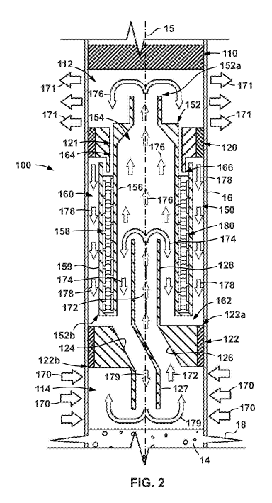
[0011] FIG. 2 is side cross-sectional view of a power generation assembly for
use within
the system of FIG. 1 according to some embodiments disclosed herein; and
[0012] FIG. 3 is a side cross-sectional view of another power generation
assembly
according to some embodiments disclosed herein.
DETAILED DESCRIPTION OF EXEMPLARY EMBODIMENTS
[0013] The following discussion is directed to various exemplary embodiments.
However,
one of ordinary skill in the art will understand that the examples disclosed
herein have
broad application, and that the discussion of any embodiment is meant only to
be
exemplary of that embodiment, and not intended to suggest that the scope of
the
disclosure, including the claims, is limited to that embodiment.
[0014] The drawing figures are not necessarily to scale.
Certain features and
components herein may be shown exaggerated in scale or in somewhat schematic
form
3
CA 03124652 2021-06-21
WO 2020/139780 PCT/US2019/068048
and some details of conventional elements may not be shown in interest of
clarity and
conciseness.
[0015] In the following discussion and in the claims, the terms "including"
and
"comprising" are used in an open-ended fashion, and thus should be interpreted
to mean
"including, but not limited to... ." Also, the term "couple" or "couples" is
intended to mean
either an indirect or direct connection. Thus, if a first device couples to a
second device,
that connection may be through a direct connection of the two devices, or
through an
indirect connection that is established via other devices, components, nodes,
and
connections. In addition, as used herein, the terms "axial" and "axially"
generally mean
along or parallel to a given axis (e.g., central axis of a body or a port),
while the terms
"radial" and "radially" generally mean perpendicular to the given axis. For
instance, an
axial distance refers to a distance measured along or parallel to the axis,
and a radial
distance means a distance measured perpendicular to the axis. As used herein,
the
terms substantial, substantially, generally, about, approximately, and the
like mean +/-
10%. Finally, any reference to up or down in the description and the claims is
made for
purposes of clarity, with "up", "upper", "upwardly", "uphole", or "upstream"
meaning toward
the surface of the wellbore or borehole and with "down", "lower",
"downwardly",
"downhole", or "downstream" meaning toward the terminal end of the wellbore or
borehole, regardless of the wellbore or borehole orientation.
[0016] As previously described above, elevated temperatures found within the
lower
regions of subterranean boreholes are a potential thermal energy source that
may be
harnessed to generate power (e.g., electrical power) for use at the surface.
One
common type of borehole that is formed in a subterranean formation is that
associated
with an oil and gas well. Typically, these wells may be drilled to a depth of
5000 to
10000 feet below the surface (depending the specific location), and may have a
bottom
hole temperature close to or over 300 F. There are a great number of such
wells that
have been drilled to access oil and gas reserves worldwide over the last two
centuries.
Once hydrocarbon production ceases or falls below an economic threshold, these
wells
are typically plugged (e.g., with cement/plugs, etc.) and abandoned. The costs
for
performing these operations may be considerable in some circumstances.
However,
these abandoned wells may still serve as an effective access point for the
geothermal
4
CA 03124652 2021-06-21
WO 2020/139780 PCT/US2019/068048
energy stored within the Earth. Therefore, embodiments disclosed herein
include
systems and methods for generating electrical power from the geothermal energy
emitted into a subterranean wellbore, such as, for example, an abandoned oil
and gas
well). In addition, as will be described in more detail below, the systems and
methods
disclosed herein may also be utilized to generate electrical power from other
sources of
thermal energy (i.e., other than a geothermal energy source).
[0017] Referring now to FIG. 1, a geothermal power generation system according
to
some embodiments is shown. System 10 generally includes a wellbore 12
extending
into a subterranean formation 6 from the surface 4. Wellbore 12 includes a
central axis
15, a first end or upper end 12a, and a second or lower end 12b opposite upper
end
12a. Upper end 12a is disposed at the surface 4, and lower end 12b is disposed
within
the subterranean formation 6. In this embodiment, wellbore 12 is substantially
vertical,
such that axis 15 is generally aligned with the vertical direction (e.g.,
along the direction
of gravity). However, in other embodiments, one or more sections or portions
of
wellbore 12 may be non-vertically oriented (e.g., lateral). A casing or liner
pipe 16 (or
more simply casing 16) is disposed within wellbore 12 and is secured in place.
In some
embodiments, casing 16 is cemented within the wellbore 12 so as to prevent
formation
fluids (e.g., oil, gas, water, etc.) from migrating to the surface 4 between
the casing 16
and the wall of wellbore 12. A plurality of perforations 18 extend through
casing 16 and
into formation 6 to provide a pathway for formation fluids into casing 16 and
ultimately
the surface 4.
[0018] In this embodiment, wellbore 12 is abandoned, and thus is plugged to
prevent
formation fluids from progressing into casing 16 and up to surface 4. In
particular, in
this embodiment cement 14 fills the lower portion of wellbore 12, from lower
end 12b to
a point above perforations 18. In other embodiments, a mechanical plug or seal
may be
placed within casing 16 above perforations 18 to similarly prevent the flow of
formation
fluids to surface 4 via casing 16. In still other embodiments, a
combination of
mechanical plugs and cement may be used to plug and abandon wellbore 12.
[0019] Referring still to FIG. 1, as previously described above, the internal
temperature
gradient of the Earth's crust results in an increasing temperature gradient
when moving
along axis 15 from the surface 4 within wellbore 12, from upper end 12a toward
lower
CA 03124652 2021-06-21
WO 2020/139780 PCT/US2019/068048
end 12b. Thus, the temperature within wellbore 12 may be higher proximate
lower end
12b than it is proximate upper end 12a. Thus, system 10 also includes a power
generation assembly 100 that is installed within wellbore 12 (particularly
within casing
16) and is configured to harness the temperature difference within the
wellbore 12 to
generate electrical power. Once generated, the electrical power may be
conducted to
the surface 4 via a conductor 52 (or a plurality of conductors) and delivered
to a final
location 50, which may include a local power grid, one or more batteries,
capacitors, or
other power storage assemblies.
[0020] It should be appreciated that power generation assembly 100 is enclosed
or
encapsulated within wellbore 12. Thus, in this embodiment, each of the
components of
power generation assembly 100 are disposed downhole (e.g., within wellbore 12)
such
that only electric current (e.g., via conductor 52) is brought back up to the
surface 4. As
a result, power generation assembly 100 may require little to no surface
space. The
details of one embodiment of power generation assembly 100 will now be
discussed in
more detail below.
[0021] Referring now to FIG. 2, an embodiment of power generation assembly 100
is
shown installed within casing 16 of wellbore 12 (see FIG. 1). Power generation
assembly 100 includes a first or upper barrier 110, a second or lower barrier
122, and a
third or middle barrier 120. Each of the barriers 110, 122, 120 are axially
spaced from
one another along axis 15 and each sealingly engages with the inner wall of
casing 16.
In this embodiment, lower barrier 122 is proximate to and axially above cement
14 and
perforations 18, and middle barrier 120 is axially disposed between upper
barrier 110
and lower barrier 122. Thus, upper barrier 110 is uphole of middle barrier 120
and
lower barrier 122, middle barrier 120 is downhole of upper barrier 110 and
uphole of
lower barrier 122, and lower barrier 122 is downhole of each of the upper
barrier 110
and middle barrier 120.
[0022] A first or upper chamber 112 is defined between upper barrier 110 and
middle
barrier 120, a second or lower chamber 114 is defined between lower barrier
122 and
cement 14, and a third or middle chamber 150 is defined between middle barrier
120
and lower barrier 122. Thus, upper chamber 112 is uphole of middle chamber 150
and
lower chamber 114, middle chamber 150 is downhole of upper chamber 112 and
uphole
6
CA 03124652 2021-06-21
WO 2020/139780 PCT/US2019/068048
of lower chamber 114, and lower chamber 114 is downhole of each of the upper
chamber 112 and middle chamber 150. In this embodiment, because power
generation
assembly 100 is installed and incorporated within casing 16 wellbore 12,
barriers 110,
120, 122 comprise plugs that are installed within casing 16.
[0023] Upper chamber 112 may be disposed within an axial section or portion of
wellbore 12 that is at a first temperature, and lower chamber 114 may be
disposed
within an axial section or portion of wellbore 12 that is at a second
temperature that is
higher than the first temperature. For example, in some embodiments, the first
temperature about the upper chamber 112 may range from 70 F to 120 F, and the
second temperature about the lower chamber 114 may range from 180 F to 300 F.
The
axial length of chambers 112, 114, 150 may be adjusted so as to place the
upper and
lower chambers 112 and 114, respectively, at predetermined depths to achieve a
desired temperature difference therebetween.
[0024] Referring still to FIG. 2, middle barrier 120 includes a central
throughbore 121
extending axially therethrough. In addition, lower barrier 122 includes a
first or upper
end 122a, a second or lower end 122b opposite upper end 122a, a first port 124
extending axially between ends 122a, 122b, and a second port 126 also
extending
axially between ends 122a, 122b that is separate from the first port 124. A
first conduit
127 extends axially from lower end 122b toward cement 14 (e.g., first conduit
127
extends axially downward or downhole) and is in fluid communication with first
port 124.
A second conduit 128 extends axially from upper end 122a toward middle barrier
120
(e.g., second conduit 128 extends axially upward or uphole) and is in fluid
communication with second port 126. Thus, the first conduit 127 and first port
124
define a first flow path through lower barrier 122 from middle chamber 150 to
lower
chamber 114, and second conduit 128 and second port 126 define a second flow
path
through lower barrier 122 from middle chamber 150 to lower chamber 114.
[0025] A central housing 152 is disposed within middle chamber 150. In
particular,
central housing 152 is disposed axially between upper barrier 110 and lower
barrier 122
and extends axially through central throughbore 121 in middle barrier 120.
Housing 152
includes a first or upper end 152a, a second or lower end 152b opposite upper
end
152a, and a central throughbore 154 extending axially between ends 152a, 152b.
7
CA 03124652 2021-06-21
WO 2020/139780 PCT/US2019/068048
Upper end 152a is disposed within upper chamber 112 and lower end 152b is
disposed
within middle chamber 150 proximate lower barrier 122. Therefore, second
conduit 128
coupled to lower barrier 122 extends into throughbore 154 of central housing
152.
[0026] An annular pocket 158 is defined within housing 152 that is radially
formed
between a radially inner annular wall 156 and a radially outer annular wall
159. Radially
inner annular wall 156 forms a portion of central throughbore 154. A
thermoelectric
generator 180 is disposed within pocket 158 radially between annular walls
156, 159
that is configured to generate electric current when exposed to two different
temperatures. Specifically, generator 180 generates electric current when a
radial
temperature gradient is applied thereto via the Seebeck Effect. The
construction of a
thermoelectric generator (e.g., like generator 180) is well known and
therefore, the
details of such a construction are not described in detail herein; however, in
general,
electric generator 180 includes dissimilar metallic materials that are exposed
(during
operation of power generation assembly 100) to different temperatures via
radial
annular walls 156, 159 to thereby generate electric current which is conducted
to the
surface 4 (e.g., via conductor 52 shown in FIG. 1).
[0027] An annular flow path 160 is defined radially between casing 16 and
radially outer
annular wall 159 that extends axially from middle barrier 120 to a manifold
region 162
within middle chamber 150 that is axially disposed between lower end 152b of
central
housing 152 and lower barrier 122. The manifold region 162 is also in fluid
communication with central throughbore 154 of housing 152 via lower end 154b
of
central housing 152 and with lower chamber 114 via first port 124 and first
conduit 127.
Thus, annular flow path 160 is in fluid communication with lower chamber 114
via
manifold region 162. In addition, annular flow path 160 is in fluid
communication with
upper chamber 112 via a flow path 164 defined between upper barrier 120 and
central
housing 152. Flow path 164 is an annular flow path that includes a U-bend 166.
As will
be described in more detail below, U-bend 166 prevents or restricts gases from
flowing
or advancing axially upward from annular flow path 160 into upper chamber 112
during
operations.
[0028] Referring still to FIG. 2, during operations, a working fluid, such as,
for example a
refrigerant is circulated within power generation assembly 100 to expose
thermoelectric
8
CA 03124652 2021-06-21
WO 2020/139780 PCT/US2019/068048
generator 180 to two different temperatures. As a result, thermoelectric
generator 180
may generate electric current which is supplied to the surface (e.g., surface
4) via a
suitable conductor or conductors (e.g., conductor 52 shown in FIG. 1).
[0029] In particular, in this embodiment, the working fluid circulated within
power
generation assembly 100 may comprise a multi-component fluid, such as, for
example,
a two component fluid. Thus, the working fluid may comprise a first fluid and
a second
fluid. The first fluid may have a first boiling point, and the second fluid
may have a
second boiling point that is higher than the first boiling point. In the
following example,
the circulated fluid within power generation assembly comprises an ammonia and
water
mixture; however, it should be appreciated that other fluid combinations may
be used in
other embodiments, and the ammonia-water mixture discussed below is merely one
potential example multi-component working fluid that may be circulated within
power
generation assembly 100.
[0030] In addition, initially the annular flow path 160 may be charged with a
gas that is
different from the components of the working fluid. In some embodiments, the
gas
charged within annular flow path 160 may be inert. In the following particular
example,
the gas charged within annular flow path 160 is helium; however, it should be
appreciated that other gases may be used in other embodiments. It should also
be
appreciated that the gas charged within annular flow path 160 (e.g., helium in
the
following described example) pressurizes the working fluid within power
generation
assembly 180 such that during the following operations, the circulated working
fluid is
maintained at a substantially constant pressure. In some embodiments, the
pressure of
the working fluid circulated within power generation assembly 180 may be
maintained
within range of -14.7 psig (-1 bar) to 150 psig (10 bar) during operations. In
other
words, the circulation of the working fluid within power generation assembly
180 (which
is described in more detail below) is achieved via changes in state (e.g.,
from liquid to
gas or from gas to liquid) and via the transfer of thermal energy, and not
from an
induced differential pressure (e.g., such as from a mechanical pump,
compressor, or the
like).
[0031] Referring still to FIG. 2, during operations of one specific
implementation, a
mixture of ammonia and water (as previously described above) is disposed
within lower
9
CA 03124652 2021-06-21
WO 2020/139780 PCT/US2019/068048
chamber 114 as the working fluid. As previously described above, lower chamber
114
is disposed at a lower depth within the wellbore 12 and thus is exposed to
relatively high
geothermal temperatures. As a result, geothermal energy is transferred from
the
formation (e.g., formation 6 in FIG. 1), through casing 16 and into the lower
chamber
114 (see e.g., arrows 170 in FIG. 2) so that the ammonia-water mixture within
lower
chamber 114 boils and emits ammonia-water vapors.
[0032] The ammonia-water vapors are then flowed (e.g., via natural convection)
axially
upward through second port 126 and second conduit 128 and are emitted into
throughbore 154 of central housing 152 (see e.g., arrows 172 in FIG. 2). The
expansion
of the ammonia-water vapors into throughbore 154 and the relatively lower
temperature
within throughbore 154 (e.g., compared to lower chamber 114), cause the water
component of the vapors to condense within throughbore 154 and settle axially
downward into manifold region 162 (see e.g., arrows 174 in FIG. 2).
Conversely, the
ammonia vapors emitted from second conduit 128 (which have a lower boiling
point
than the water) continue upward in a gaseous state and are emitted from
throughbore
154 into upper chamber 112 via upper end 152a of central housing 152 (see
e.g.,
arrows 176 in FIG. 2). Therefore, during operations, the radially inner wall
156 of
annular pocket 158 within central housing 152 is exposed to the relatively
high
temperatures of the ammonia and water vapors flowing through throughbore 154.
In
some embodiments, the radially inner wall 156 may be exposed to temperatures
ranging from 180 F to 300 F during these operations.
[0033] Referring still to FIG. 2, upon entering upper chamber 112, the heated
ammonia
vapors are exposed to the relatively lower temperatures of upper chamber 112
that
result from the relatively lower temperature of the formation (e.g., formation
6 in FIG. 1)
at the shallower depth of chamber 112. Accordingly, upon entering the upper
chamber
112, thermal energy is transferred from the ammonia vapors back into the
formation
(see e.g., arrows 171 in FIG. 2) such that the ammonia vapors cool and
condense to a
liquid that then flows through flow path 164 into annular flow path 160. As
previously
described, the annular flow path 160 is filled with a gas, which in this
example
comprises helium. The helium is prevented from flowing back up through flow
path 164
into upper chamber 112 by liquid ammonia that is disposed within U-bend 166 of
flow
CA 03124652 2021-06-21
WO 2020/139780 PCT/US2019/068048
path 164. Upon entering annular flow path 160, the ammonia liquid is exposed
to the
helium gas and therefore expands (e.g., evaporates) or diffuses back into a
gaseous
state as it generally flows or progresses axially downward through annular
flow path 160
toward manifold region 162 (see e.g., arrows 178 in FIG. 2).
[0034] The evaporation of the ammonia liquid into gas within annular flow path
160
cools the ammonia significantly so that the annular wall 159 defining annular
flow path
160 is exposed to relatively low temperatures. For example, in some
embodiments, the
radially outer wall 159 may be exposed to temperatures ranging from -40 F to 0
F
during these operations. Thus, thermoelectric generator 180 is exposed to a
relatively
large temperature difference or gradient between the radially inner wall 156
and radially
outer wall 159 of annular pocket 158. For example, in some embodiments, the
temperature difference between the radially inner wall 156 and radially outer
wall 159
may range from 175 F to 340 F. Because the electrical current generation of
thermoelectric generator 180 may be directly proportional to the temperature
difference
that is applied thereto, this relatively large temperature difference may
allow
thermoelectric generator 180 to generate a relatively large amount of electric
current. In
addition, thermoelectric generators (e.g., such as generator 180) may also
operate a
greater efficiencies in lower temperature environments. Thus, by additionally
cooling
the working fluid (e.g., ammonia) as it flows through the annular flow path
160, the
overall temperature exposed to the thermoelectric generator 180 may be
decreased
such that generator 180 may operate at an enhanced efficiency.
[0035] Referring still to FIG. 2, as the evaporated ammonia vapors flow
axially
downward toward manifold region 162, they are once again condensed back into a
liquid such that the liquefied ammonia may be mixed with the liquid water
within
manifold region 162 (which was condensed from throughbore 154 as previously
described above ¨ see e.g., arrows 174). Thereafter, the ammonia-water mixture
may
be flowed from manifold region 162 back into lower chamber 114 via first port
124 and
first conduit 127 (see e.g., arrows 179 in FIG. 2) such that the above
described cycle
may be repeated.
[0036] As a result, during operations with power generation assembly 100, a
working
fluid (e.g., a refrigerant such as the ammonia-water mixture previously
described above)
11
CA 03124652 2021-06-21
WO 2020/139780 PCT/US2019/068048
is continuously circulated in a closed-loop at a relatively constant pressure
to thereby
expose thermoelectric generator to a large temperature gradient. Accordingly,
through
use of the geothermal temperature gradient along axis 15 of wellbore 12, power
generation assembly 180 may generate electric current that is conducted to the
surface
4 via a suitable conductor or conductors (e.g., conductor 52 in FIG. 1).
[0037] In the embodiment described above, power generation assembly 100 (see
FIG.
2) is incorporated within the casing 16 of a subterranean wellbore 12.
However, in other
embodiments, the power generation assembly (e.g., assembly 100) may be a self-
contained unit or assembly that is constructed at the surface (e.g., surface 4
in FIG. 1)
and lowered into the wellbore (e.g., wellbore 12). For example, referring now
to FIG. 3,
a power generation assembly 200 is shown. Power generation assembly 200 is
generally the same as power generation assembly 100, and thus, components of
power
generation assembly 200 that are shared with power generation assembly 100 are
identified with like reference numerals and the description below will focus
on the
features of power generation assembly 200 that are different from power
generation
assembly 100.
[0038] Primarily, power generation assembly 200 omits upper barrier 110 and
instead
includes an outer housing 202 that has a central axis 205 and surrounds each
of the
middle barrier 120 and lower barrier 122. As a result, outer housing 202 also
partially
defines each of the chambers 110, 114, 150 previously described above. In
particular,
outer housing 202 includes a first or upper end 202a, and a second or inner
end 202b
opposite upper end 202a. Upper chamber 110 is defined within housing 202
between
upper end 202a and middle barrier 120, and lower chamber 114 is defined within
housing 202 between lower end 202b and lower barrier 122. In addition, middle
chamber 150 is defined within housing 202 axially between middle barrier 120
and
lower barrier 122. Further, because barriers 120, 122 are disposed within
housing 202,
they may be mechanical plugs that engage with the inner wall of housing 202 or
they
may be incorporated or integrated within the walls of housing 202 itself.
[0039] Referring still to FIG. 3, operations with power generation assembly
200 are
substantially the same as those described above for power generation assembly
100,
and thus, the details of which are not repeated herein in the interests of
brevity.
12
CA 03124652 2021-06-21
WO 2020/139780 PCT/US2019/068048
However, because power generation assembly 200 is a self-contained unit,
assembly
200 is first lowered into a wellbore (e.g., wellbore 12 in FIG. 1) such that
upper and
lower chambers 110 and 114, respectively, are disposed at appropriate depths
so as to
be exposed to a desired temperature difference due to the geothermal
temperature
gradient of a subterranean wellbore. Once the desired temperature difference
is
achieved between upper and lower chambers 110 and 114, respectively,
operations
with power generation assembly 200 (particular the circulation of fluids
therein) may be
conducted in substantially the same manner as previously described above so
that
electric current is generated by thermoelectric generator 180. Upon the
cessation of
operations (e.g., at the end of power generation operations altogether or
during
maintenance periods), the power generation assembly 200 may be simply pulled
to the
surface (e.g., surface 4) via appropriate lifting equipment.
[0040] In addition, because power generation assembly 200 is a self-contained
unit
within outer housing 202, it may be operated to generate electrical power in
other
environments that include a temperature gradient, other than a subterranean
wellbore
(e.g., wellbore 12). For example, power generation assembly 200 may be placed
in any
location or apparatus that exposes chambers 110, 114 to different temperatures
to
thereby drive the circulation of the working fluid contained therein (e.g.,
ammonia and
water as previously described above) to result in the generation of electrical
power via
thermoelectric generator 180 as previously described above. For example, power
generation assembly 200 may be operated in an industrial facility (e.g.,
chemical plant,
refinery, manufacturing facility, etc.) where fluids or materials are
circulated at various
temperatures in furtherance of other manufacturing or chemical processing
operations.
[0041] Through use of the power generation assemblies described herein (e.g.,
power
generation assemblies 100, 200), electrical current may be generated from an
existing
temperature gradient. In some embodiments, the existing temperature gradient
may be
a temperature gradient disposed within a subterranean wellbore (e.g., such as
that
associated with an oil and gas well) generated by geothermal energies drawn
from the
interior of the Earth. Accordingly, these existing temperature gradients may
be
harnessed to generate electricity for use in other processes or locations.
13
CA 03124652 2021-06-21
WO 2020/139780 PCT/US2019/068048
[0042] While exemplary embodiments have been shown and described,
modifications
thereof can be made by one skilled in the art without departing from the scope
or
teachings herein. The embodiments described herein are exemplary only and are
not
limiting. Many variations and modifications of the systems, apparatus, and
processes
described herein are possible and are within the scope of the disclosure.
Accordingly,
the scope of protection is not limited to the embodiments described herein,
but is only
limited by the claims that follow, the scope of which shall include all
equivalents of the
subject matter of the claims. Unless expressly stated otherwise, the steps in
a method
claim may be performed in any order. The recitation of identifiers such as
(a), (b), (c) or
(1), (2), (3) before steps in a method claim are not intended to and do not
specify a
particular order to the steps, but rather are used to simplify subsequent
reference to
such steps.
14