Note: Descriptions are shown in the official language in which they were submitted.
CA 03124717 2021-06-23
SECTIONAL CONTROL FOR AIR BOOM SPREADER
Field
This application relates to agriculture, in particular to an air boom spreader
equipped with sectional control for selectively delivering solid agricultural
product to a field.
Background
Air boom spreaders are well known in the art for delivering liquid or solid
products
(e.g. fertilizers) to an environment (e.g. a field) around the spreader. Air
boom spreaders
typically comprise one or more boom arms that extend transversely to a
direction of travel
of the spreader in order to cover a large swath of ground in one pass. Product
is delivered
from a container by a product distribution system to spaced outlets on the
boom arm for
delivery to a field.
In many instances, the driving plan of the spreader and/or the layout of the
field can
cause misapplication of the product to an undesired area. In some cases, there
is overlap
in certain areas over which a boom arm passes, thereby causing redundant
application of
the product to those certain areas. In other cases, the spreader may pass
close to a non-
productive area causing misapplication of the product to the non-productive
area. Such
misapplications of product lead to greater expense due to product wastage and
to uneven
results across a field, for example growing results of a crop being fertilized
by the spreader.
The ability to selectively prevent product application by one or of the
outlets, especially
without needing to stop the spreader, would help mitigate the problem of
misapplication of
product to undesired areas.
There remains a need in the art for an air boom spreader having sectional
control
for selectively delivering product, in particular a solid agricultural
product, to areas of a field.
Summary
In one aspect, there is provided an air boom spreader comprising: a frame; a
boom
arm extendible transversely to a direction of travel of the spreader; a
container mounted on
1
Date Recue/Date Received 2021-06-23
CA 03124717 2021-06-23
WO 2020/146937
PCT/CA2020/050031
the frame for containing a solid product to be delivered to an environment
around the
spreader; a product distribution system in product communication with the
container for
receiving the product from the container; and, an air system in product
communication with
the distribution system for receiving the product from the distribution
system, the air system
comprising an air line mounted on the boom arm, the air line connecting the
product
distribution system to a product outlet situated on the boom arm to permit
passage of the
product from the product distribution system to the environment through the
product outlet,
and a fan assembly comprising at least a fan, the fan in fluid communication
with the air
line and operable to create air flow in the air line to transport the product
from the product
distribution system to the product outlet, wherein the product distribution
system comprises
at least one endless solid product metering assembly, the solid product
metering assembly
comprising: a first endless conveyor and a second endless conveyor for
conveying the
product from the container to the air system, the first and second endless
conveyors
substantially parallel to each other, the first conveyor driven independently
of the second
conveyor; and, a first shaft, a second shaft and a third shaft, the first
shaft parallel to,
separated from and driven independently of the second shaft, the second shaft
parallel to
and separated from the third shaft, the first shaft driving the first
conveyor, the second shaft
driving the third shaft to drive the second conveyor.
To drive the conveyors, motors, for example hydraulic, pneumatic or electric
motors,
or any other suitable drive means may be used. In some embodiments, the
metering
assembly may comprise a first motor for driving the first shaft to drive the
first conveyor. In
some embodiments, the metering assembly may comprise a second motor for
driving the
second shaft to drive the third shaft to drive the second conveyor. In order
for the second
shaft to drive the third shaft, the second shaft may be connected to the third
shaft by a drive
linkage. Any suitable drive linkages may be used, for example drive belts,
drive chains,
toothed gears or combinations thereof. In some embodiments, the metering
assembly may
comprise a geared linkage between the second shaft and the third shaft. In
some
embodiments, the geared linkage may comprise a first toothed gear mounted on
the third
shaft and a second toothed gear mounted on the second shaft, the first and
second toothed
gears connected by a drive chain.
When more than one metering assembly is present in the spreader, the metering
assemblies are generally placed in close proximity, for example side-by-side.
For this
reason, there is not enough space between metering assemblies to accommodate
the
presence of a motor. It is an advantage of the present invention that a
plurality of motors,
for example the first and second motors, may be situated at a same side of the
metering
2
CA 03124717 2021-06-23
WO 2020/146937
PCT/CA2020/050031
assembly. As well, a plurality of drive linkages may be situated at a side of
the metering
assembly opposite the plurality of motors, for example the first and second
toothed gears
as well as the drive chain may be situated at the side of the metering
assembly opposite
the first and second motors. A drive linkage has a slimmer profile than a
motor and occupies
less space. Therefore, it is possible to include more than one metering
assembly to
selectively deliver product to different portions of distribution system for
selective control of
product delivery to the environment. This is not possible, or at least much
more difficult, in
configurations where the motors are on opposite sides of the metering
assembly.
To assist with the configuration of a plurality of motors on the same side of
the
metering assembly, the metering assembly may comprise split drive rollers and,
in some
embodiment, split idler rollers. In some embodiments, the metering assembly
may
comprise a first drive roller for the first conveyor and a second drive roller
for the second
conveyor, the first drive roller mounted on the first shaft and the second
drive roller mounted
on the third shaft. In some embodiments the second shaft may be longitudinally
separated
from the third shaft. In some embodiments, the first shaft may be coaxial with
the third shaft.
In some embodiments, the metering assembly further comprises an idler roller
mounted
around the second shaft. In some embodiments, the metering assembly may
comprise a
first idler roller for the first conveyor and a second idler roller for the
second conveyor, the
first and second idler rollers mounted around the second shaft, the first and
second idler
rollers rotatable independently of each other.
The metering assembly described herein advantageously permits independent
operation of endless conveyors within the metering assembly and independent
operation
of the endless conveyors of adjacent metering assemblies while permitting the
adjacent
metering assemblies to be close enough together to feed solid product to
different closely
spaced protions of the product distribution system. The use of multiple
individually
controllable endless conveyors, each distributing product to fewer portions of
the
distribution system permits sectional control in an air boom spreader for
selectively
delivering product to areas of a field.
Further, the arrangement described herein for independently powering two
endless
conveyors in a single metering assembly can be extended to powering more than
two
endless conveyors in a single metering assembly. The addition of more motors
longitudinally separated on the same side of the metering assembly together
with more
transversely oriented shafts, appropriate placement of drive and idler rollers
on the shafts
and appropriate placement of drive linkages between the shafts can permit the
use of more
than two endless conveyors in a single metering assembly, all the endless
conveyors
3
CA 03124717 2021-06-23
WO 2020/146937
PCT/CA2020/050031
spaced closely enough together to ultimately permit the use of a single
independently
controlled endless conveyor to feed a single small portion (e.g. a single
funnel) of the
product distribution system thereby providing very fine sectional control of
product delivery
to the environment around the air boom spreader.
Further features will be described or will become apparent in the course of
the
following detailed description. It should be understood that each feature
described herein
may be utilized in any combination with any one or more of the other described
features,
and that each feature does not necessarily rely on the presence of another
feature except
where evident to one of skill in the art.
Brief Description of the Drawings
For clearer understanding, preferred embodiments will now be described in
detail
by way of example, with reference to the accompanying drawings, in which:
Fig. 1A is an isometric view of one embodiment of an air boom spreader of the
present invention;
Fig. 1B is a top view of the spreader of Fig. 1A without a cover on a product
container;
Fig. 1C is a rear view of the spreader of Fig. 1A;
Fig. 2A is an isometric view of a left-side metering assembly of the spreader
of Fig.
1A;
Fig. 2B is a top view of the left-side metering assembly of Fig. 2A;
Fig. 2C is a rear view of the left-side metering assembly of Fig. 2A;
Fig. 2D is a right-side view of the left-side metering assembly of Fig. 2A;
Fig. 3A is an isometric view of a left-hand motor drive assembly of the left-
side
metering assembly of Fig. 2A;
Fig. 3B is a top view of the left-hand motor drive assembly of Fig. 3A;
Fig. 3C is a rear view of the left-hand motor drive assembly of Fig. 3A;
Fig. 3D is a right-side view of the left-hand motor drive assembly of Fig. 3A;
4
CA 03124717 2021-06-23
WO 2020/146937
PCT/CA2020/050031
Fig. 4A is an isometric view of a direct drive motor unit of the left-hand
motor drive
assembly of Fig. 3A;
Fig. 4B is a top view of the direct drive motor unit of Fig. 4A;
Fig. 4C is a rear view of the direct drive motor unit of Fig. 4A;
Fig. 4D is a right-side view of the direct drive motor unit of Fig. 4A;
Fig. 5A is an isometric view of a chain drive motor unit of the left-hand
motor drive
assembly of Fig. 3A;
Fig. 5B is a top view of the chain drive motor unit of Fig. 5A;
Fig. 50 is a rear view of the chain drive motor unit of Fig. 5A;
Fig. 5D is a right-side view of the chain drive motor unit of Fig. 5A;
Fig. 6A is a rear view of drive rollers of the left-hand motor drive assembly
of Fig.
3A;
Fig. 6B is a sectional view of the drive rollers of Fig. 6A;
Fig. 60 is an exploded view of the drive rollers of Fig. 6A;
Fig. 6D depicts the drive rollers of Fig. 6A showing internal assembly in
detail A;
Fig. 6E depicts detail A of Fig. 6D magnified at a scale of 1:2;
Fig. 7A is a rear view of idler rollers of the left-hand motor drive assembly
of Fig.
3A;
Fig. 7B is a sectional view of the idler rollers of Fig. 7A;
Fig. 70 is an exploded view of the idler rollers of Fig. 7A;
Fig. 8A is a top view of a tensioner roller assembly of the left-side metering
assembly of Fig. 2A;
Fig. 8B is a rear view of the tensioner roller assembly of Fig. 8A;
Fig. 80 is a left-side view of the tensioner roller assembly of Fig. 8A;
Fig. 8D is a rear view of tensioner rollers of the tensioner roller assembly
of Fig. 8A;
5
CA 03124717 2021-06-23
WO 2020/146937
PCT/CA2020/050031
Fig. 8E is a sectional view of the tensioner rollers of Fig. 8D; and,
Fig. 8F is an exploded view of the tensioner rollers of Fig. 8D.
Detailed Description
With reference to the Figures and particular reference to Fig. 1A, Fig. 1B and
Fig.
10, one embodiment of an air boom spreader 1 of the present invention
comprises a frame
2, a pair of boom arms 3a, 3b mounted on the frame 2 at a rear of the spreader
1, each of
boom arms 3a, 3b extendible transversely to a direction of travel of the
spreader 1, one
boom arm 3a extendible to the left and the other boom arm 3b extendible to the
right of the
spreader 1. While two boom arms are illustrated, the spreader may comprise 1,
2, 3, 4 or
more boom arms if desired. The air boom spreader 1 also comprises a product
container 4
mounted on the frame 2, the container 4 comprising at least one hopper for
containing a
solid product (e.g. fertilizer, herbicide, seed and any other desired granular
product) to be
delivered to an environment (e.g. a field) around the spreader I. The
container 4 may be
covered by a cover 5 if desired, as illustrated in Fig. 1A. The container may
comprise 1, 2,
3, 4 or more hoppers, if desired, which can be used to contain different kinds
of product, if
desired. Wheels (not shown) may be mounted on the frame 2 to facilitate
movement of the
spreader 1 on the ground. A hitch 6 may be mounted at a front of the frame 2
to permit
hitching the spreader Ito a prime mover, for example a tractor, a truck or the
like. However,
the air boom spreader may be self-propelled instead, if desired.
The air boom spreader 1 also comprises a product distribution system 10 in
product
communication with the container 4 for receiving the solid product from the
container 4 and
an air system 15 in product communication with the distribution system 10 for
receiving the
product from the distribution system 10 and delivering the product to the
environment. The
distribution system 10 comprises a left-side endless solid product metering
assembly 12
and a right-side endless solid product metering assembly 13. The product
metering
assemblies 12, 13 extend longitudinally into the container 4 from left and
right meter boxes
14a, 14b, respectively, mounted at a rear of the container 4. The left-side
endless solid
product metering assembly 12 distributes product to the left meter box 14a for
delivery to
the left side of the spreader 1, and right-side endless solid product metering
assembly 13
distributes product to the right meter box 14b for delivery to the right side
of the spreader
1. The product metering assemblies 12, 13 receive solid product from the
container by
gravity and deliver the product to respective meter boxes 14a, 14b. The meter
boxes 14a,
14b each comprise a plurality of funnels (not shown) into which the solid
product is
distributed, preferably evenly, by the product metering assemblies 12, 13 in a
manner
6
CA 03124717 2021-06-23
WO 2020/146937
PCT/CA2020/050031
generally known in the art. The product metering assemblies 12, 13 are
operable
independently of each other, which permits changing the relative speeds of the
metering
assemblies 12, 13 and therefore the relative delivery rate of product to each
side of the
spreader 1. Delivery of the product to one side of the spreader 1 may be
achieved by turning
off the appropriate metering assembly.
The product metering assemblies 12, 13 are shown parallel and transversely
separated in the same horizontal plane; however, the product metering
assemblies may be
vertically separated as upper and lower product metering assemblies. Further,
while the
product metering assemblies 12, 13 are shown as being parallel, the product
metering
assemblies may instead form an angle with each other transporting product in
non-parallel
directions. Furthermore, while two product metering assemblies are shown, more
than two
product metering assemblies may be employed, if desired, for example, 3, 4, 5,
6 or more
product metering assemblies.
The air system 15 comprises a plurality of air lines 17a, 17b (only two
labeled, one
on each side of the spreader 1) mounted on the boom arms 3a, 3b, respectively.
The
plurality of air lines connects the plurality of funnels of the meter boxes of
the product
distribution system 10 to a plurality product outlets 18a, 18b (only two
labeled, one on each
side of the spreader 1) situated at regular intervals along the boom arms 3a,
3b to permit
passage of the product from the product distribution system 10 to the
environment through
the plurality of product outlets. A fan assembly 16 comprising at least a fan
is in fluid
communication with the plurality of air lines and is operable to create air
flow in the plurality
of air lines to transport the product from the product distribution system 10
to the plurality
of product outlets. The fan assembly 16 may further comprise a fan motor for
operating the
fan, or the fan may be operated by a motor remotely situated on the spreader
1.
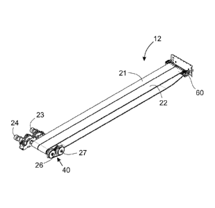
With particular reference to Fig. 2A to Fig. 8F, the left-side endless solid
product
metering assembly 12 will now be described. The right side endless solid
product metering
assembly 13 is constructed and operates in a similar manner.
The left-side solid product metering assembly 12 comprises a first endless
conveyor
21 (e.g. a belt, sometimes called a chain) and a second endless conveyor 22
(e.g. a belt,
sometimes called a chain) for conveying the product from the container 4 to
the meter
boxes 14a, 14b and thence to the air system 15. The first and second endless
conveyors
21, 22 are substantially parallel to each other and may have substantially
coplanar upper
surfaces. The first conveyor 21 is driven independently of the second conveyor
22. The
metering assembly 12 further comprises a first motor 23 to drive the first
conveyor 21 and
7
CA 03124717 2021-06-23
WO 2020/146937
PCT/CA2020/050031
a second motor 24 to drive the second conveyor 22. The first and second motors
23, 24
are not coaxial. The first and second motors 23, 24 are longitudinally spaced
apart at the
same side of the metering assembly 12. The first and second motors 23, 24 are
situated at
a same side of the metering assembly 12 because there is insufficient space
between the
left-side solid product metering assembly 12 and the right-side solid product
metering
assembly 13 to accommodate the presence of a motor. How the two motors 23, 24
can
independently drive the two conveyors 21, 22 despite the two motors 23, 24
being on the
same side of the metering assembly 12 next to the first endless conveyor 21 is
described
below.
The first motor 23 is directly attached to a first shaft 25 of a drive roller
assembly
30. The drive roller assembly 30 comprises a left sprocketed drive roller 31
seated around
and drivingly engaged with the first shaft 25. The left sprocketed drive
roller 31 comprises
at least one and preferably a plurality of sprockets 32 (only one labeled)
that engage with
engagement elements on an underside of the first endless conveyor 21 proximate
a rear
of the first conveyor 21. The engagement elements may be, for example,
apertures in or
protrusions on the underside of the first endless conveyor 21. Operation of
the first motor
23 rotationally drives the first shaft 25, which rotationally drives the left
sprocketed drive
roller 31, which in turn rotationally drives the first endless conveyor 21.
The second motor 24 is directly attached to a second shaft 26 extending
transversely across a width of the left-side solid product metering assembly
12, including
across widths of both the first and second endless conveyors 21, 22 at a rear
of the solid
product metering assembly 12. The second shaft is parallel to, longitudinally
separated
from and driven independently of the first shaft 25. A geared linkage 40
operatively
connects the second shaft 26 to a third shaft 27. The second shaft 26 is
parallel to and
longitudinally separated from the third shaft 27. The third shaft 27 is part
of the drive roller
assembly 30 and is coaxial with the first shaft 25. The drive roller assembly
30 comprises
a right sprocketed drive roller 33 seated around and drivingly engaged with
the third shaft
27. The right sprocketed drive roller 33 comprises at least one and preferably
a plurality of
sprockets 34 (only one labeled) that engage with engagement elements on an
underside
of the second endless conveyor 22. Operation of the second motor 24
rotationally drives
the second shaft 26, which rotationally drives the third shaft 27, which
rotationally drives
the right sprocketed drive roller 33 of the drive roller assembly 30, which in
turn rotationally
drives the second endless conveyor 22. With specific reference to Fig. 6A to
Fig. 6E, the
drive roller assembly 30 comprises left and right bushings 51, 52,
respectively, that support
free ends of the first shaft 25 and third shaft 27 within a shaft connector
50. The first shaft
8
CA 03124717 2021-06-23
WO 2020/146937
PCT/CA2020/050031
25 and third shaft 27 are able to freely and independently rotate within the
shaft connector
50 by virtue of the bushings 51, 52. The roller 31 is drivingly engaged with
the first shaft 25
at first engagement structure 55, while the roller 33 is drivingly engaged
with the third shaft
27 at second engagement structure 57. A belt separator 54 attached to and
extending
vertically downward from the shaft connector 50 keeps the first and second
endless
conveyors 21, 22 from interfering with each other during operation. The shaft
connector 50
is seated inside the sprocketed drive rollers 31, 33.
With specific reference to Fig. 5A to Fig. 5D, the geared linkage 40 that
operatively
connects the second shaft 26 to the third shaft 27 comprises a first toothed
gear 41
mounted on the third shaft 27 and a second toothed gear 42 mounted on the
second shaft.
The first and second toothed gears 41, 42, respectively, are connected by a
drive chain 43.
The first and second toothed gears 41, 42, respectively, are situated at a
side of the
metering assembly 12 opposite the first and second motors 23, 24,
respectively. Because
the geared linkage 40 has a much slimmer profile than the first and second
motors 23, 24,
it is possible to mount the geared linkage 40 in the narrow space between the
left-side and
right-side product metering assemblies 12, 13 (see Fig. 1B).
With specific reference to Fig. 7A to Fig. 70, the second shaft 26 is mounted
within
a first floating idler roller 36 and a second floating idler roller 37. The
second shaft 26 is
seated in bushings 38 within the idler rollers 36, 37 so that the second shaft
26 is able to
freely rotate within the idler rollers 36, 37 without driving the idler
rollers 36, 37, and so that
the idler rollers 36, 37 may rotate independently of each other in response to
operation of
respective first and second endless conveyors 21, 22. A belt separator 39
between the idler
rollers 36, 37 helps prevent the first and second endless conveyors 21, 22
from interfering
with each other during operation. In this manner, the second motor 24 can
drive the second
shaft 26 to drive the third shaft 27 to drive the second endless conveyor 22
without
interference from the first endless conveyor 21. As seen in Fig. 2A, the
second shaft 26
along with first and second idler rollers 36, 37 are situated at the rear end
of the metering
assembly 12 where the first and second endless conveyors 21, 22 loop around
the first and
second idler rollers 36, 37, respectively.
At the front end of the metering assembly 12, the metering assembly 12
comprises
a tensioner roller assembly 60 around which the first and second endless
conveyors 21, 22
loop, as shown in Fig. 8A to Fig. 8F. The tensioner roller assembly 60
comprises a
transversely oriented tensioner shaft 61 around a first portion of which a
first sprocketed
tensioner roller 62 is fixedly mounted and around a second portion of which a
second
sprocketed tensioner roller 63 is rotatably mounted. The first sprocketed
tensioner roller 62
9
CA 03124717 2021-06-23
WO 2020/146937
PCT/CA2020/050031
rotates with the tensioner shaft 61, while the second sprocketed tensioner
roller 63 freely
rotates around the tensioner shaft 61. While the first tensioner roller is
shown fixedly
mounted, the second tensioner roller could be fixedly mounted instead. In some
embodiments, neither of the tensioner rollers may be fixedly mounted on the
tensioner
shaft. Proximate ends of the tensioner shaft 61, the tensioner shaft 61 is
rotatably seated
in take-up bearings 64, which are mounted to a mounting plate 65, which is
mounted to an
inside of a front wall of the container 4. Each of the take-up bearings 64
comprises a
threaded bolt and nut arrangement 66, which can be operated to tension the
endless
conveyors 21, 22. The tensioner roller assembly 60 further comprises belt
separators 68
mounted on the tensioner shaft 61 and lock collars 67 proximate each end of
the tensioner
shaft 61 to hold the rollers 62, 63 and belt separators 68 in place on the
tensioner shaft 61.
All rollers may be provided with oil ports 70 (only some shown and labeled) to
permit
lubricating the various shafts, and the oil ports may be plugged with plugs 71
(only some
shown and labeled) to prevent oil leaks.
In some embodiments, the third shaft need not be coaxial with the second
shaft, but
may instead be longitudinally separated from both the first shaft and the
second shaft. All
three of the shafts may extend the entire width of the product metering
assembly, in which
case idler rollers may be mounted around appropriate sections of the first and
third shafts.
In addition or alternatively, intermediate support structures between the
first and second
endless conveyors may be used to support ends of the first and/or third
shafts.
Further, in embodiments where the first endless conveyor is vertically
separated
from the second endless conveyor, the first and second shafts are vertically
separated, and
the second and third shafts are vertically separated, without the need for the
second shaft
to be longitudinally separated from the first and third shafts. With
vertically separated
endless conveyors, a fourth shaft is required and idler rollers may be mounted
on the
second and fourth shafts. With vertically separated endless conveyors, another
tensioner
roller assembly is required at the front of the metering assembly, one for
each endless
conveyor.
The metering assembly described herein advantageously permits independent
operation of endless conveyors within the metering assembly and independent
operation
of the endless conveyors of adjacent metering assemblies while permitting the
adjacent
metering assemblies to be close enough together to feed solid product to
different closely
spaced funnels in the meter boxes of the product distribution system. The use
of multiple
individually controllable endless conveyors, each distributing product to
fewer funnels
CA 03124717 2021-06-23
WO 2020/146937
PCT/CA2020/050031
permits sectional control in an air boom spreader for selectively delivering
product to areas
of a field.
Further, the arrangement described herein for independently powering two
endless
conveyors in a single metering assembly can be extended to powering more than
two
endless conveyors in a single metering assembly. The addition of more motors
longitudinally separated on the same side of the metering assembly together
with more
transversely oriented shafts, appropriate placement of drive and idler rollers
on the shafts
and appropriate placement of geared linkages between the shafts can permit the
use of
more than two endless conveyors in a single metering assembly, all the endless
conveyors
spaced closely enough together to ultimately permit the use of a single
independently
controlled endless conveyor to feed a single funnel of the product
distribution system. A
one-to-one correspondence of endless conveyor to funnel provides for very fine
sectional
control of product delivery to the environment around the air boom spreader.
The novel features will become apparent to those of skill in the art upon
examination
of the description. It should be understood, however, that the scope of the
claims should
not be limited by the embodiments, but should be given the broadest
interpretation
consistent with the wording of the claims and the specification as a whole.
11