Note: Descriptions are shown in the official language in which they were submitted.
CA 03124984 2021-06-25
1
MECANUM WHEELS APPLIED TO THE SYSTEM FOR MOVING A SUSPENDED
MOBILE PLATFORM ON VERTICAL AND HORIZONTAL FLAT SURFACES
FIELD OF THE INVENTION
[0001] The present invention refers to technologies for ship and oil
platform
equipment, in addition to building maintenance. More specifically, the present
invention
relates to robot-automated painting technology.
BACKGROUND OF THE INVENTION
[0002] Large flat vertical surfaces are currently maintained or
inspected by
means of building access, such as using climbing harnesses or scaffolding. In
order to
paint, an employee must be able to access the location to be painted.
[0003] In shipbuilding, access is by scaffolding, as the work is done
in dry dock.
This access is financially expensive and time-consuming. Furthermore, it
involves work
safety risks.
[0004] To inspect or paint large areas, various technologies for
movement may
be employed, such as carts with magnetic wheels, paddle systems with suction
cups, and
rail installation in parts, among other solutions. These solutions are time-
consuming and
ineffective when using a painting system.
[0005] There is a need to reproduce the type of painting done by an
employee.
This means that there are certain variables to consider in performing the
work. One of
these is the linear manner in which the painting system applies paint. The
movement of
an employee that is considered to be the most effective is usually rectilinear
(horizontal
or vertical), stopping application at the ends. Since the speed in the
inversion of
movement is zero at these endpoints, the painting system could overspray. To
prevent
overspray, the mechanism of the paint application gun is stopped until it
returns to its
normal application speed.
[0006] Several technologies for mobile inspection of metal surfaces
may be
used, such as the use of carts with magnetic wheels, paddle systems with
suction cups,
installation of rails on the parts, among other solutions.
[0007] Document U53876255A discloses a wheel design with bearings
that
have an angle of approximately 45 with respect to the wheel axis. It has an
open side
structure where the rollers are exposed to the coating, which can be damaged
with its
entry, consequently causing the wheel to lock. Therefore, the model does not
meet the
stipulated requirements for it to be used in a painting system in which the
wheels come
Date Recue/Date Received 2021-06-25
CA 03124984 2021-06-25
2
into contact with the coating. Furthermore, regarding the adopted roller
model, it has a
structure with a central bearing, making it even less suitable for use in
painting systems.
[0008] Tavakoli et al. (Magnetic Omnidirectional Wheels for Climbing
Robots)
reveals omnidirectional magnetic wheels adapted for movement in 3D
ferromagnetic
structures, such as vertical walls and ceilings. The magnets are arranged on
the periphery
of the wheels and follow their movement.
[0009] As the magnets are not fixed and remain parallel to the
contact surface
at all times, we can identify a variation in magnetic force during the
vehicle's movement,
considering the geometric and constructive factors, which implies difficulty
in using
painting systems because it impacts the homogeneity of the coating to be
applied.
[00010] As will be further detailed below, the present invention aims
to solve the
problems of the state-of-the-art described above in a practical and efficient
manner.
SUMMARY OF THE INVENTION
[00011] The approach in this application is aimed at painting large
vertical walls
and consists of using a suspended mobile platform on controlled cables,
allowing a large
surface area to be covered using a lightweight modular infrastructure.
[00012] The suspended mobile platform is positioned by the cables,
with its
suspension system placed on free Mecanum wheels that act like spheres.
Additionally,
the wheels are provided with a proximity magnet system, which allows the
device not to
move away from the metal wall; the magnets in turn do not contact the surface
of the
metal wall, ensuring they do not damage the surface. This same principle
applies to the
rollers comprising the wheels, which are constructed of a material and have a
geometrical
design that prevents the surface from being damaged.
[00013] Various technologies for movement may be employed, such as
carts with
magnetic wheels, paddle systems with suction cups, and rail installation in
parts, among
other solutions.
[00014] The proposed system of Mecanum wheels must consider the
following
issues: clear irregular surfaces, be capable of moving along x and y
coordinates
(Cartesian plane), not impact the painted surface by using polymeric
components in the
rollers.
[00015] On uneven surfaces, furthermore, the wheels must cross side
weld
seams up to 3 mm wide in any direction. Because the magnets are away from the
contact
surface, it is possible to move over obstacles that are up to 10 mm in height,
ensuring
that the device can pass over any unevenness on side surfaces, including
obstacles such
Date Recue/Date Received 2021-06-25
CA 03124984 2021-06-25
3
as screws and weld beads, ensuring that the magnetic force continues to act on
the
surface.
[00016] Roller bearings allow for washing after coming into contact
with the
coatings.
[00017] The wheels do not require lubrication due to the use of
shielded external
weather-resistant bearings.
[00018] The movement speed must be such that it meets a minimum
process
speed. This minimum speed may be around 105 m2 per hour.
[00019] The wheels together with the system were designed to minimize
coating
losses during the painting process. The wheels are designed so that fresh
paint does not
get inside them. And after curing, the wheels do not damage the coating that
was applied.
[00020] The strategy used in the painting process is not to paint
while
descending, and to paint while ascending, such that the main obstacles will be
faced in
the process, as if descending stairs. Shifting to a side section will occur at
the top of the
hull when the ropes are very taut, and therefore momentum will be tightly
controlled.
There is no interference from the obstacles during painting. The movement of
the mobile
platform is independent of obstacles. The movement is mainly related to not
passing over
a newly painted region. The robot was developed to pass over obstacles without
interfering with the painting.
[00021] The wheels feature a set of magnets arranged in a line under a
central
base and parallel to the surface where movement will occur.
[00022] In addition to the oil and gas industry, this technology may
be used in civil
construction.
BRIEF DESCRIPTION OF THE FIGURES
[00023] The detailed description presented below references the
attached figures
and their respective reference numbers.
[00024] Figure 1 details the arrangement of magnets and rollers.
[00025] Figure 2 shows the arrangement of rollers, bearings and the
cylindrical
shape of the wheel.
[00026] Figure 3 shows the wheels fitted to the platform, where the
assembly
adapts to different surface curvatures.
[00027] Figure 4 shows examples of surfaces with irregularities with
the
proposed adapted wheel system.
[00028] Figure 5 shows the robotized paint assembly in which the wheel
system
Date Recue/Date Received 2021-06-25
CA 03124984 2021-06-25
4
(mobile platform) is used.
DETAILED DESCRIPTION OF THE INVENTION
[00029] The objective of the present invention is to adopt a
characteristic type of
wheel to be applied to a robotized painting system, with the main
characteristics of high
reliability, capacity to move very quickly, resistance to the type of coating
applied, low
need for lubrication of the bearings, good ability to pass over irregularities
and obstacles
on the surface and not be affected (be resistant) by the painting process,
including the
paint from the application process, making the wheels resistant to fresh
paint.
[00030] In order to achieve the objectives described above, the
present invention
provides a set of magnets arranged in line under a central base and parallel
to the surface
where movement will take place. Wheels behave like spheres.
[00031] Additionally, the wheels are provided with a proximity magnet
system,
which allows the device not to move away from the metal wall; the magnets in
turn do not
contact the surface of the metal wall, ensuring they do not damage the
surface. This same
principle applies to the rollers comprising the wheels, which are constructed
of a material
and have a geometrical design that prevents the surface from being damaged.
[00032] Regarding the ability to pass over obstacles, as the magnets
are away
from the contact surface, it is possible to move over obstacles that are up to
20 mm in
height, ensuring that the device can pass over any unevenness on side
surfaces,
including obstacles such as screws and weld beads, ensuring that the magnetic
force
continues to act on the surface.
[00033] A preferred embodiment of the invention will be presented
below. As will
be apparent to anyone skilled in the art, however, the invention is not
limited to that
particular embodiment.
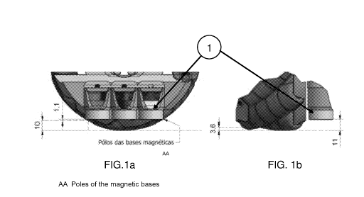
[00034] The magnetic base (1) is located between two wheel covers (2).
The
poles of the magnetic base are pointed directly at the surface where the
contact is made
by the wheels, directly on the rollers (3). Thus, the magnetic force is
uniform, does not
depend on the rollers (3) and there is no contact with the surface. The
rollers (3), in turn,
are arranged in several units along the wheel cover (2), preferably placed at
45 , but they
are not limited to this layout. The rollers (3) are hollow inside, allowing
the use of bearings
(4) and preventing the bearings from being impacted by coating entering in.
Figure 1a
details the magnetic base coupled to one of the wheel covers (2). Figure lb
details the
rollers, in a cylindrical shape along its body, but with a variable diameter,
with a larger
diameter in the center and a smaller diameter on the sides. Thus, the shape of
the roller
(3) along its body is convex in the direction of contact with the surface.
Date Recue/Date Received 2021-06-25
CA 03124984 2021-06-25
[00035] The same figures, 1a and lb, show the ability to pass over
obstacles that
are parallel up to 10 mm and perpendicular to the wheel axles up to 3.6 mm.
The obstacle
could be bigger, but it is limited by the magnetic bases, which have an
expected height
of 20 mm, resulting in a clearance of 1 mm. Thus, the height limit is not on
the wheel
covers (2) or rollers (3), but on the height of the magnetic base.
[00036] The height of the magnetic base, which may be adjusted
depending on
the need for more adherence, is determined by the trade-off between clamping
force and
the risk of blocking in the event it has to pass over or avoid a collision. If
the poles have
zero air gaps, the force would be too great, which could block the robot's
descent. In this
case, therefore, the assembly would only have traction from the weight. Thus,
in order to
have this characteristic of being able to pass over obstacles, the diameter of
the wheels,
which was initially 100 mm, increases to 172 mm, but they are not limited to
this specific
size.
[00037] Figure 2 shows the rollers (3) arranged at 45 between the
wheel covers
(2). The rollers (3) are hollowed for the passage of the bearings (4). The
rollers are free
of bearings (5). The wheel covers (2) are hollowed to receive the rollers (3)
with fastening
for screws. The bearings (5) are insulated (shielded) on the wheels and thus
are
unaffected by contact with the paint coating. The wheel covers (2) are like
the hubcaps
on a vehicle that do not come into contact with the surface and that serve to
support the
rollers (3).
[00038] Figure 3 shows the wheel assembly (Mecanum wheels) attached to
the
mobile platform (6), designed to cushion and adjust to surface deformities.
The radius of
curvature where the mobile platform is used is around 2000 m, fully designed
according
to the characteristics of the Mecanum wheels.
[00039] Figure 4 shows lines of obstacles that the wheels must be able
to pass
over. The biggest "steps" are the variations of plates on the hull, always
horizontal lines,
which in the design of the replicating platforms are on the external surface
of the hull,
precisely the one that will be painted. The decrease in thickness is always at
the bottom
of the hull to the first uncovered deck. Other steps of lower height are the
weld beads,
which go in all directions. The strategy used so that obstacles disturb the
painting process
as little as possible is not paint while descending, and to paint while
ascending.
[00040] Figure 5 shows a mobile platform (6) attached to the painting
platform,
serving as an example of use of the mobile platform (6), but not restricted to
operating
only with the painting platform. The set of Mecanum wheels (7), connected to
the mobile
platform, is shown, usually around four "4." The mobile platform is being
claimed in
Date Recue/Date Received 2021-06-25
CA 03124984 2021-06-25
6
another patent application.
[00041] We inform you that the use of Mecanum wheels is not restricted
to the
embodiment shown here, as they may be used in any application.
Date Recue/Date Received 2021-06-25