Note: Descriptions are shown in the official language in which they were submitted.
CA 03125430 2021-06-29
WO 2020/142206 PCT/US2019/066921
NASAL DRUG DELIVERY DEVICE
CROSS REFERENCE To RELATED APPLICATIONS
[0001] This application claims the benefit of priority to U.S. Provisional
Patent Application
No. 62/788,093, filed on January 3, 2019, entitled "Nasal Drug Delivery
Device" which is
incorporated herein by reference in its entirety for all purposes.
BACKGROUND
[0002] This disclosure relates generally to a drug delivery device, and
specifically to a nasal
drug delivery device for delivering drugs to an upper nasal cavity of a user.
[0003] The central nervous system (CNS) includes the brain, the brain stem,
and the spinal
cord. The CNS is isolated from the external world by several membranes that
both cushion and
protect the brain, the brain stem, and the spinal cord. For example, the
membranes that form the
blood-brain barrier (BBB) protect the brain from certain contents of the
blood. The blood-
cerebrospinal fluid barrier (BCSFB) protects other portions of the CNS from
many chemicals
and microbes.
[0004] Traditional methods for delivering compounds to the CNS are
typically invasive. For
example, a pump implanted in the skull, such as an intracerebroventricular
pump, can deliver a
variety of compounds to the brain. However, implanting such a pump requires
brain surgery,
which can entail a variety of serious complications. Certain compounds, for
example epidural
painkillers, can be injected directly through the protective membrane into the
CNS. However,
such injection is impractical for most compounds.
[0005] Intranasal administration has traditionally focused on the
distribution of drug
solutions as a mist for topical delivery to the nasal epithelium. Because of
the nasal cavity's
1
CA 03125430 2021-06-29
WO 2020/142206 PCT/US2019/066921
easily accessed vascular bed, nasal administration of medications has focused
the delivery of
medications either locally to the nasal cavity or directly to the blood
stream.
[0006] Much of the current brain research is focused on the enhancement of
the drug being
delivered to the brain by various formulations. The traditional approaches to
improve uptake of
compounds to the brain by formulation enhancement include (1) mucoadhesive
formulations; 2)
penetration enhancers; 3) liposomes; 4) vasoconstrictors; and 5)
nanoparticles. Examples of
various compounds with have enhanced formulations include various cytokines,
for example,
tumor necrosis factors, interleukins, and interferons discussed in U.S. Pat.
No. 6,991,785 and
growth and differentiation factor-5 (GDF-5) and related proteins discussed in
US Publication No.
20100074959.
[0007] Targeting of drugs to the central nervous system (CNS) is a
challenging task. A great
number of drugs, including biotechnology products, are candidates for
treatment of CNS
diseases, but drug delivery is a problem for brain targeting. A limitation in
the treatment of brain
tumors is that less than 1% of most therapeutic agents administered
systemically are able to cross
the BBB. The transport of small molecules across the BBB is the exception
rather than the rule,
and 98% of all small molecules do not cross the BBB (Pardride, NeuroRx. 2005
January; 2(1): 1-
2. 2005); approximately 100% of large-molecule drugs or genes do not cross the
BBB (Pardride,
NeuroRx. 2005 January; 2(1): 1-2. 2005). The BBB allows small (about less than
500 Da),
lipophilic molecules from the bloodstream to enter the CNS (Pardridge, Arch
Neurol. 2002;
59:35-40). Many larger therapeutic agents are prevented from reaching the
brain for treating
CNS disorders such as but not limited to Parkinson's disease, Alzheimer's
disease, depression,
stroke, and epilepsy (Pardridge, NeuroRx. 2005 January; 2(1): 3-14). Disorders
including autism,
lysosomal storage disorders, fragile X syndrome, ataxis, and blindness, are
serious disorders
where there is little effective treatment. In many of these cases, the gene
underlying the disease is
known, but BBB delivery is the rate-limiting problem in gene therapy or enzyme
replacement
therapy, and no therapeutics have been developed. Drug delivery of therapeutic
compounds, for
example proteins, faces several challenges because of their instability, high
enzymatic
metabolism, low gastrointestinal absorption, rapid renal elimination, and
potential
immunogenicity.
[0008] There is a need for devices that can deliver compounds to the upper
nasal cavity for
direct nose-to-brain delivery. Certain existing nasal drug delivery devices do
not adequately
2
CA 03125430 2021-06-29
WO 2020/142206 PCT/US2019/066921
propel the drug from the device. Inconsistent propulsion of drug due to
inconsistent user
actuation is also far from optimal. For example, some existing devices are
manually actuated and
may be used in conjunction with a manual pump, such that the actuation of the
device is
dependent on a user's rate and/or strength of actuation of the pump. Some
existing devices
require the user to coordinate their breathing with device actuation, which
can produce variable
results due to differences in a user's breath power. In addition, some drug
products are in an
encapsulated form, which requires the capsule to be opened or punctured to
administer the drug,
which may result in particulate matter from the capsule contaminating the
drug. Even further, in
a metered dose inhaler (MDI) type device, some drug products do not readily
mix and/or stay
suspended with propellants.
[0009] Better mechanisms for administering desired agents to the brain,
brain stem, and/or
spinal cord are needed.
SUMMARY
[0010] A device for delivering a compound to the upper nasal cavity is
described. In one
embodiment, the device includes a housing body comprising an actuator, a stem,
and a release
button. The actuator is configured to move relative to the housing body, where
actuation of the
actuator is configured to actuate a canister thereby releasing a contained
propellant. The stem
protrudes from the housing body and comprises a mating interface that mates
with a nozzle
containing the compound. The release button is positioned within the housing
body and moves
relative to the housing body. The release button is directly connected to a
securing mechanism
that couples the nozzle to the mating interface, where actuation of the
release button decouples
the nozzle from the mating interface.
[0011] In one embodiment, the nozzle comprises a nozzle body, a diffuser,
an outlet orifice,
a removable seal, and a receiving cavity. The nozzle body comprises a channel
that extends
between a proximal end and a distal end of the nozzle body, and the diffuser
is positioned within
the channel. The outlet orifice is disposed at a distal end of the channel,
and the removable seal is
positioned across the outlet orifice. The compound is contained within the
channel between the
diffuser and the removable seal, and the removable seal may be removed by a
user before the
3
CA 03125430 2021-06-29
WO 2020/142206 PCT/US2019/066921
compound is administered. The receiving cavity is disposed about an outer
surface of the nozzle
body and receives a reciprocal mating interface of the device.
[0012] Upon user actuation of the device, the released propellant travels
to the channel of the
nozzle body, contacts the diffuser, and propels the compound out the outlet
orifice for delivery
into the upper nasal cavity. In this configuration, the device administers the
dose to the upper
nasal cavity independent of the user's breathing and/or user's rate and/or
strength of actuation. In
addition, the nozzle may be coupled to and decoupled from the housing body.
The nozzle is used
to deliver a single dose of the compound, such that after dispensing the dose,
the nozzle may be
removed from the housing body and a new nozzle may be attached for delivering
a future dose.
This configuration maintains the integrity of the compound contained within
the detachable
nozzle and consistently administers the dose to the upper nasal cavity.
BRIEF DESCRIPTION OF THE DRAWINGS
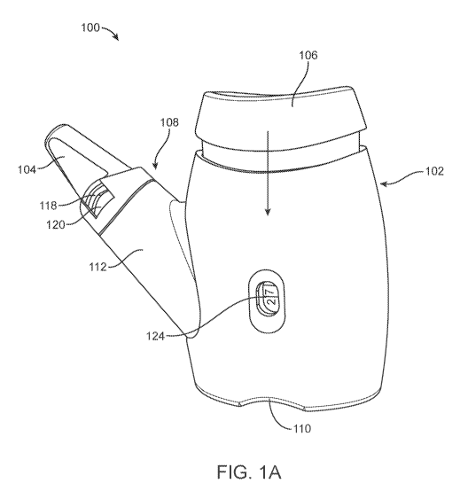
[0013] Figure (FIG.) lA illustrates a perspective view of a nasal drug
delivery device, in
accordance with one or more embodiments.
[0014] FIG. 1B illustrates a side view of the device of FIG. lA with a
nozzle detached, in
accordance with one or more embodiments.
[0015] FIG. 2 illustrates a cross-sectional view of the device of FIGS. lA
and 1B, in
accordance with one or more embodiments.
[0016] FIGS. 3A and 3B illustrate a side view and a cross-sectional view,
respectively, of an
internal assembly housed within the device of FIGS. lA and 1B, in accordance
with one or more
embodiments.
[0017] FIGS. 4A and 4B illustrate an exploded view and a cross-sectional
view, respectively,
of a nozzle, in accordance with one or more embodiments.
[0018] FIGS. 5A and 5B illustrate an exploded view and a cross-sectional
view, respectively,
of a nozzle, in accordance with one or more embodiments.
[0019] FIGS. 6A and 6B illustrate an exploded view of the internal assembly
and the internal
assembly seated within a housing body, respectively, in accordance with one or
more
embodiments.
4
CA 03125430 2021-06-29
WO 2020/142206 PCT/US2019/066921
[0020] FIGS. 7A-7C illustrate an internal surface of the housing of the
device of FIGS. lA
and 1B and a release button, in accordance with one or more embodiments.
[0021] FIG. 8 a perspective, partially exploded view of the device of FIGS.
lA and 1B, in
accordance with one or more embodiments.
[0022] The figures depict embodiments of the present disclosure for
purposes of illustration
only. One skilled in the art will readily recognize from the following
description that alternative
embodiments of the structures and methods illustrated herein may be employed
without
departing from the principles, or benefits touted, of the disclosure described
herein.
DETAILED DESCRIPTION
[0023] Unless defined otherwise, all technical and scientific terms used
herein have the same
meaning as commonly understood by one of ordinary skill in the art pertinent
to the methods and
compositions described. As used herein, the following terms and phrases have
the meanings
ascribed to them unless specified otherwise:
[0024] As used herein the specification, "a" or "an" may mean one or more.
[0025] A "diagnostic agent" refers to and encompasses an atom, molecule, or
compound that
is useful in diagnosing a disease. Diagnostic agents include, but are not
limited to, radioisotopes,
dyes, contrast agents, fluorescent compounds or molecules and enhancing agents
(e.g.,
paramagnetic ions). A non-radioactive diagnostic agent is a contrast agent
suitable for magnetic
resonance imaging, computed tomography, or ultrasound. The diagnostic agent
can be used to
perform positron emission tomography (PET), MRI, X-ray, CT, ultrasound,
operative,
intravascular, laparoscopic, or endoscopic procedure.
[0026] A "diffuser" refers to and encompasses a component for dispersing or
deflecting a
compound in various directions.
[0027] A "frit" is one type of a diffuser and shall refer to and encompass
a porous member or
filter.
[0028] An "imaging agent" refers to and encompasses an atom, molecule or
compound that
is useful in detecting physical changes or produces images of internal body
tissues. In some
aspects, the imaging agent may be a diagnostic agent.
CA 03125430 2021-06-29
WO 2020/142206 PCT/US2019/066921
[0029] A "propellant" shall refer to and encompass a compound that acts as
a vehicle for
creating propulsion or thrust.
[0030] The term "therapeutically effective amount" refers to and
encompasses an amount of
a drug effective to treat a disease or disorder in a mammal. In one aspect,
the therapeutically
effective amount refers to a target CNS concentration that has been shown to
be effective in, for
example, slowing disease progression. Efficacy can be measured in conventional
ways,
depending on the condition to be treated.
[0031] The term "treatment" and "treat", and the like, refers to and
encompasses therapeutic
or suppressive measures for a disease or disorder leading to any clinically
desirable or beneficial
effect, including, but not limited to, alleviation or relief of one or more
symptoms, regression,
slowing or cessation of progression of the disease or disorder. Treatment can
be evidenced as a
decrease in the severity of a symptom, the number of symptoms, or frequency of
relapse.
[0032] A "user" or "subject" shall refer to and encompass a human or other
animal. For
example, the animal may be a primate or a non-primate and may include a
rabbit, bovine, equine,
pig, rat, mouse, dog or cat.
[0033] The device may be used in treatment, prevention, palliative care for
humans and
veterinary purposes. The device may be used in research and industrial uses.
For example, the
device may be used to deposit compound in agricultural settings.
[0034] When trade names are used herein, applicants intend to independently
include the
trade name product formulation, the generic drug, and the active
pharmaceutical ingredient(s) of
the trade name product.
[0035] For clarity of disclosure, and not by way of limitation, the
detailed description of the
invention is divided into the subsections which follow.
[0036] Intranasal administration of compounds to the upper nasal cavity
offers several
advantages over traditional surgical, intravenous or oral routes for
administration across the
blood brain barrier (BBB). The upper nasal cavity may include the olfactory
region and the
middle and superior turbinate regions, among other regions within the nasal
cavity. Intranasal
administration to specifically the olfactory region avoids gastrointestinal
destruction and hepatic
first pass metabolism, such as destruction of drugs by liver enzymes, allowing
more drug to be
cost-effectively, rapidly, and predictably bioavailable than if it were
administered orally.
Intranasal administration provides ease, convenience and safety. Intranasal
drug administration is
6
CA 03125430 2021-06-29
WO 2020/142206 PCT/US2019/066921
generally painless (taking into consideration that pain may be a subjective
measurement which
varies by patient) and does not require sterile technique, intravenous
catheters or other invasive
devices, and is generally immediately and readily available for all patients.
Intranasal
administration can rapidly achieve therapeutic brain and spinal cord drug
concentrations.
[0037] Nasally administered compounds contact the upper olfactory region
and molecular
transport occurs directly across this tissue and into compartments of the
central nervous system.
(Henry, R. J., et al., Pediatr Dent, 1998. 20(5): p. 321-6; Sakane, T., et
al., J Pharm Pharmacol,
1991. 43(6): p. 449-51; Banks, W. A., et al., J Pharmacol Exp Ther, 2004.
309(2): p. 469-75;
Westin, et al., Pharm Res, 2006. 23(3): p. 565-72). The olfactory mucosa is
located in the upper
nasal cavity, just below the cribriform plate of the skull. It contains
olfactory cells which traverse
the cribriform plate and extend up into the cranial cavity. When compounds
come in contact with
this specialized mucosa, they are rapidly transported directly into the brain,
they bypass the
BBB, and are rapidly transported directly into the central nervous system,
often faster than if the
compound is given intravenously.
[0038] The olfactory mucosa includes the olfactory epithelium. The
olfactory epithelium is
located at the top of the nose between the superior turbinate and the roof of
the nasal cavity, just
beneath the cribriform plate of the ethmoid bone. In humans, it covers about
10 to about 20 cm2,
or about 8% of the total nasal surface area, and is composed of four main cell
types: epithelial
cells, olfactory receptor neurons, supporting cells, and basal cells.
(Mathison S. et al., (1998)
Journal of Drug Targeting 5: 415-441). Although 3% of the nasal cavity is
occupied by olfactory
epithelium (Morrison and Costanzo, 1990), this route is direct, since the
olfactory neurons do not
have a synapse between the receptive element and the afferent path (Ding and
Dahl, 2003). The
olfactory epithelium is more than twice the depth of the respiratory
epithelium, with the olfactory
nerve cell bodies typically located in the middle and deeper regions of the
epithelium while
nuclei of the supporting cells are organized in a single layer closer to the
mucosal surface. Tight
junctions exist between the supporting cells and between the supporting cells
and olfactory nerve
cells. Morrison E. E, et al. (1992) Journal of Comparative Neurology 297(1): 1-
13.
[0039] When a nasal drug formulation is delivered deep and high enough into
the nasal
cavity, the olfactory mucosa is reached and drug transport into the brain
and/or CSF via the
olfactory receptor neurons occurs. The transfer of compounds from the nose to
the brain is
referred to as the nose-brain pathway. The nose-brain pathway has implications
when centrally
7
CA 03125430 2021-06-29
WO 2020/142206 PCT/US2019/066921
acting medications such as but not limited to sedatives, anti-seizure drugs,
and opiates are
delivered nasally. The present device allows for delivery via the nose-brain
pathway allowing for
nearly immediate delivery of nasal medications to the central nervous system
and brain, by-
passing the blood brain barrier.
[0040] The current challenge in nose-to-brain drug delivery is also due to
the complex
architecture of the nose, which is naturally designed to channel drugs into
the lower nasal airway
toward the lungs making it difficult for drugs to reach the olfactory region.
Most of the drug
dispensed from traditional nasal devices such as sprayers or pumps is
subjected to the natural air
movement in the nasal cavity towards the esophagus. The majority of the spray
dispensed from
traditional devices encounters the natural downward airflow displacement
within the nasal
cavity. The remaining fraction from traditional devices is found in the
respiratory epithelium and
cleared by the mucocilliary clearance mechanism or absorbed into the blood
stream. While nasal
catheter instillation and nose drops are less impacted by this natural
downward air movement, it
requires subjects to be in a supine position, is often associated with user
discomfort, and is not
optimal for frequent clinical administration.
[0041] Moreover, a reservoir of residual air exists at the top of the nasal
cavity that is not
removed during normal respiration, thus remaining in the olfactory region and
acting as a barrier
to deposition. This residual air must be displaced in order to deliver
aerosolized drug to the
olfactory epithelium in the upper nasal cavity in a consistent manner. The
device described
herein delivers a majority of the aerosolized drug to the upper part of the
nasal cavity to increase
exposure of the drug at the olfactory epithelium, a site of nose-to-brain
pathway, by both
avoiding the natural downward air movement and displacing the residual air of
the upper nasal
cavity.
[0042] The device herein advantageously and consistently deposits a large
fraction of dose
into the more distal parts of the nasal cavity such as the olfactory region. A
drug product (also
referred to herein as drug formulation, drug compound, or intranasal dosage
form) is propelled
from the device with a velocity into the nasal cavity.
[0043] FIGS. lA and 1B illustrate a perspective view of a nasal drug
delivery device 100 and
a side view of the device 100 with the nozzle detached, respectively, in
accordance with one or
more embodiments. The device 100 is designed to deliver a drug compound to an
upper nasal
cavity of a user. The drug compound may be a liquid, powder, or some
combination thereof. In
8
CA 03125430 2021-06-29
WO 2020/142206 PCT/US2019/066921
various embodiments, the device 100 may deliver a single dose or a multi-dose,
may be single-
use or reusable, may be manually actuated and propellant-driven, or some
combination thereof.
In the embodiments of FIGS. lA and 1B, the device 100 is propellant-driven,
delivers a single
dose, and may be reused to deliver several individual doses. In the
embodiments of FIGS. lA
and 1B, the device 100 comprises a housing body 102, a nozzle 104 that
contains the drug
compound, an actuator 106, and a coupling interface 108 that couples the
nozzle 104 to the
housing body 102. The nozzle 104 may be coupled to the housing body 102 for
delivery of the
dose, as shown in FIG. 1A, and may be decoupled from the housing body 102, as
shown in FIG.
1B, after the drug compound is dispensed into an upper nasal cavity of the
user. A new nozzle
104 may be coupled to the housing body 102 for delivery of a subsequent dose.
[0044] The housing body 102 represents the body of the device 100. The
housing body 102
is designed to be held in a hand of a user and may include one or more
ergonomic features for
the comfort of the user. For example, in the embodiment of FIGS. lA and 1B,
the housing body
102 includes an indentation 110 that allows a user to comfortably hold and
engage the device
100 with the fingers, for example a thumb positioned on the indentation 110
and one or more
fingers positioned on top of the actuator 106. In the embodiment of FIGS. lA
and 1B, the
housing body 102 is composed of two "clamshells" pieces that conceal an
internal assembly of
the device 100 and retain all of the components in alignment to ensure
functionality. A top
portion of the housing body 102 couples with the actuator 106 such that the
actuator 106 moves
relative to the housing body 102. In this configuration, the user may apply a
vertical downward
force (in the direction of the arrow) to the actuator 106 to actuate the
device 100. In alternate
embodiments, the housing body 102 and the actuator 106 may be arranged in a
different
orientation such that the user applies a vertical upward force, a horizontal
force, a diagonal force,
or some combination thereof to the actuator 106 to actuate the device 100. A
stem 112 of the
housing body 102 couples to the nozzle 104 via the coupling interface 108.
[0045] The nozzle 104 contains the drug compound. In the embodiment of
FIGS. lA and 1B,
the nozzle 104 is a single-use nozzle, where the nozzle 104 holds a single
dose and may be
replaced after each use. The nozzle 104 includes a channel (shown in FIG. 2)
that holds the drug
compound and an outlet orifice at a distal end (shown in FIG. 2) of the nozzle
104 through which
the drug compound may exit the nozzle 104. Housed within the housing body 102
is a propellant
canister (shown in FIG. 2) that is in fluid communication with the channel of
the nozzle 104,
9
CA 03125430 2021-06-29
WO 2020/142206 PCT/US2019/066921
such that propellant released from the canister travels through the nozzle
channel and propels the
drug compound out the outlet orifice. In the embodiments of FIGS. lA and 1B,
the nozzle 104
may be coupled to and decoupled from the stem 112 via the coupling interface
108.
[0046] The actuator 106 is manually actuated by a user to dispense a dose
from the nozzle
104. The actuator 106 moves relative to the housing body 102 (e.g., slides,
translates, rotates, or
other similar motion). In the embodiment of FIGS. 1A and 1B, the actuator 106
translates in a
vertical motion, represented by the direction of the arrow. The actuator 106
is coupled to the
propellant canister (shown in FIG. 2) housed within the housing body 102. In
this configuration,
actuation of the actuator 106 causes actuation of the propellant canister,
thereby releasing
propellant that travels through the housing body 102 to the channel of the
nozzle 104 and propels
the drug compound out the outlet orifice of the nozzle 104.
[0047] The coupling interface 108 couples the nozzle 104 to the housing
body 102 and
decouples the nozzle 104 from the housing body 102 upon actuation of a release
button 116. In
the embodiment of FIG. 2, the coupling interface 108 comprises a mating
interface 114 on the
stem 112, a reciprocal mating interface (shown in FIGS. 4-5) on the nozzle
104, the release
button 116 which is directly connected to a securing latch 118, and an opening
120 that receives
the securing latch 118. Specifically, the mating interface 114 of the stem 112
couples the
reciprocal mating interface of the nozzle 104.
[0048] In the embodiments of FIGS. lA and 1B, the mating interface 114
comprises one or
more protruding tabs 121, and the reciprocal mating interface is a receiving
cavity, where the
receiving cavity receives the one or more protruding tabs 121. In alternate
embodiments, the
configuration of the receiving cavity and protruding tabs 121 may be reversed
(e.g., on opposite
components). The mating interface 114 comprises one or more holes 122 such
that the securing
latch 118 protrudes through a respective hole 122. To couple the nozzle 104 to
the housing body
102, the nozzle 104 is positioned onto the stem 112 such that the receiving
cavity receives the
one or more protruding tabs 121. The opening 120 receives the securing latch
118, which secures
the nozzle 104 to the housing body 102. In the embodiments of FIGS. lA and 1B,
the securing
latch 118 is directly connected to the release button 116, where actuating the
release button 116
causes movement of the securing latch 118. To decouple the nozzle 104 from the
housing body
102, the release button 116 is actuated, and the securing latch 118 is
displaced from the opening
120. The coupling mechanism is discussed in further detail in FIGS. 6-7. In
one embodiment, an
CA 03125430 2021-06-29
WO 2020/142206 PCT/US2019/066921
outer surface of the nozzle 104 and an outer surface of the stem 112 are flush
when coupled
together.
[0049] In some embodiments, the device 100 includes a dose counter 124. The
dose counter
124 tracks the number of actuations of the propellant canister, such that a
user may be aware of
the amount of propellant remaining in the propellant canister. For example, a
propellant canister
may have a capacity for distributing propellant for a certain number of doses.
In some
embodiments, the propellant canister may be replaced with a new propellant
canister, such that
the device 100 may be reused. In one aspect, when a MDI device is actuated, a
discrete amount
of pressurized HFA fluid is released. The MDI may contain between about 30 to
about 300
actuations, inclusive of endpoints, of HFA propellant. The amount of fluid
propellant released
upon actuation may be between about 20 microliters (i.1.1) and about 200
microliters (i.1.1) inclusive
of endpoints, of liquid propellant.
[0050] FIG. 2 illustrates a cross-sectional view of the device of FIGS. lA
and 1B, in
accordance with one or more embodiments. The cross-sectional view exposes the
internal
assembly within the housing body 102 and the mating interfaces between the
nozzle 104 and the
housing body 102. In the embodiment of FIG. 2, the internal assembly comprises
a propellant
canister 202 and a junction 204 that couples to the nozzle 104, the junction
204 having a
propellant channel 206.
[0051] The propellant canister 202 contains propellant. In one embodiment,
the propellant
may be pressurized. The propellant is a fluid, for example, a liquid or gas.
In one aspect, the
propellant is a liquid. In another aspect, the propellant is a gas.
Propellants include
pharmaceutically suitable propellants. Some examples of pharmaceutically
suitable propellants
include hydrofluoroalkane (HFA) including but not limited to HFA, HFA 227, HFA
134a, HFA-
FP, HFA-BP and the like HFA's. In one aspect, the propellant is liquid HFA. In
another aspect,
the propellant is gaseous HFA. Additional examples of suitable propellants
include nitrogen or
choloroflourocarbons (CFC). Additionally, propellants may be pressurized air
(e.g. ambient air).
[0052] The canister 202 may be a metered dose inhaler (MDI) device that
includes a
pressurized canister and metering valve 208 (including stem) to meter the
propellant upon
actuation. In one embodiment, a pump fitment (not shown) secures the metered
valve 208 to the
canister 202 and holds both components in place during device 100 use. One
series of
embodiments of the pump fitment consists of securing interfaces that retain
the pump fitment
11
CA 03125430 2021-06-29
WO 2020/142206 PCT/US2019/066921
within the housing body 102, provide vertical displacement, and prevent
rotation during
installation of the canister 202. As shown in FIG. 2, the canister 202 is
coupled to the actuator
106. A portion of the canister 202 is positioned within a cavity 210 of the
actuator 106 such that
movement of the actuator 106 causes actuation of the canister 202 (i.e., the
canister 202 moves
relative to the metering valve 208, thereby releasing propellant). In the
embodiment of FIG. 2,
the canister 202 is coupled to the junction 204 such that the metering valve
208 is in fluid
communication with the propellant channel 206. In this configuration, the
propellant in the
canister 202 acts as a vehicle to deliver propulsion or thrust to expel the
drug compound from the
nozzle 104.
[0053] The junction 204 is an internal structure that couples the canister
202 to the nozzle
104. The propellant channel 206 extends through the junction 204, thereby
creating a flow path
from the canister 202 to the nozzle 104. As shown in FIG. 2, the junction 204
comprises a base
212, a first branch 214, and a second branch 216. The first branch 214 and the
second branch 216
both extend from the base 212. In the embodiment of FIG. 2, the first branch
214 couples to the
metering valve 208, and the second branch 216 couples to the nozzle 104. The
propellant
channel 206 extends from the proximal end of the first branch 214 to the
distal end of the second
branch 216 and is in fluid communication with the canister 202 and the nozzle
104. Propellant
released from the canister 202 travels through the propellant channel 206 to
the nozzle 104. In
alternate embodiments, the junction 204 may have a varying number of branches
that may be in
a different arrangement. For example, an angle between the branches may vary
between 0 to 180
degrees. In one series of embodiments, the angle is 30 degrees, 35 degrees, 40
degrees, 45
degrees, 50 degrees, 55 degrees, 60 degrees, inclusive of endpoints and
intervening degrees.
[0054] The distal end of the second branch 216 couples with the nozzle 104.
Specifically, the
distal end of the second branch 216 is inserted into a nozzle channel 218 when
the nozzle 104 is
positioned onto the stem 112. The distal end of the second branch 216 may have
a tapered end
and/or a chamfer to facilitate insertion into the nozzle channel 218. In the
embodiment of FIG. 2,
the distal end of the second branch 216 comprises a sealing ring 220 that
creates an airtight seal
between the junction 204 and an internal surface of the nozzle channel 218.
The sealing ring 220
may be an o-ring or an x-ring (lubricated or non-lubricated). In the
embodiment of FIG 2, the
sealing ring 220 is an x-ring, which has a lower insertion force than an o-
ring when the distal end
of the second branch 216 is inserted into the nozzle channel 218. Stated
differently, an x-ring
12
CA 03125430 2021-06-29
WO 2020/142206 PCT/US2019/066921
does not have to deform as much as an o-ring to be positioned within the
nozzle channel 218.
This configuration decreases both the stiffness of the sealing ring 220 and
the potential friction
created by the sealing ring 220, which enables a user to easily couple and
decouple the nozzle
104 to and from the device 100, thus improving the user experience. In
addition, the x-ring is
non-lubricated, which prevents lubricant from leeching onto other components
of the device 100
or a user of the device.
[0055] As shown in FIG. 2, the nozzle 104 comprises the nozzle channel 218,
an outlet
orifice 222, and a diffuser 224. The nozzle channel 218 extends between a
proximal end and a
distal end of the nozzle 104. The outlet orifice 222 is an opening at the
distal end of the nozzle
104. The diffuser 224 is positioned within the channel such that the diffuser
224 spans across the
diameter of the nozzle channel 218. The drug compound is positioned within the
nozzle channel
218 between the diffuser 224 and the outlet orifice 222. In this
configuration, the nozzle channel
218 is in fluid communication with the propellant channel 206 such that
propellant released from
the canister travels through the propellant channel 206, into the nozzle
channel 218, contacts the
diffuser 224, and propels the drug compound out the outlet orifice 222.
[0056] The diffuser 224 diffuses propellant released from the canister 202.
In one aspect, a
majority of the propellant is diffused via the diffuser. In another aspect, a
minority of the
propellant is diffused via the diffuser. Majority refers to and encompasses at
least 50 percent.
Minority refers to and encompasses less than 50 percent. In another aspect, at
least about 10%,
15%, 20%, 25%, 30%, 35%, 40%, 45%, 50%, 55%, 60%, 65%, 70%, 75%, 80%, 85%,
90%,
95%, 99% or about 100%, inclusive of endpoints, of the propellant is diffused
via the diffuser.
The diffuser 224 is in communication with the nozzle channel 218.
[0057] In some aspects, the diffuser 224 functions to convert propellant
from a liquid to a
gas. Specifically, the diffuser 224 expands the propellant from a liquid state
to a gaseous state. In
other aspects, the diffuser 224 functions to prevent the drug compound
contained in the nozzle
channel 218 from coming in contact with the canister 202. In another aspect,
the diffuser acts as
a one-way check valve. In other aspects, the diffuser 224 functions to convert
propellant from a
liquid to a gas and to prevent the compound contained in the nozzle channel
218 from coming
into contact with the canister 202. In yet another aspect, the diffuser
functions to increase the
temperature of the propellant. In one aspect, the diffuser converts the liquid
propellant into a
13
CA 03125430 2021-06-29
WO 2020/142206 PCT/US2019/066921
gaseous state, which then aerosolizes the drug compound and propels the
aerosolized drug
compound through the nozzle channel 218 and out the outlet orifice 222.
[0058] An example of a diffuser 224 includes a frit, a plurality of frits,
or a diffuser member
or combinations thereof. In one aspect, the diffuser is a frit. In another
aspect, the diffuser is a
plurality of frits. In another aspect, the diffuser is a diffuser member.
[0059] In one aspect, the frit(s) are of any suitable size and shape and
are formed using any
suitable porous material of any suitable density. In one aspect, the frit is
made of a hydrophobic
material. In one aspect, the frit is made of an inert material to avoid
chemically reacting with any
of the compounds. The inert material may be metal or non-metal. In one aspect,
the frit is
composed of metal. In another aspect, the frit is composed of a non-metal. In
one aspect, the
inert material is sintered nickel. As one example, a frit formed using a
porous stainless steel
having a pore size in the range of approximately 1 micron to approximately 100
microns can be
used. In another aspect the pore size is in the range of about 1 to about 10,
about 10 to about 20,
about 20 to about 30, about 30 to about 40, about 40 to about 50, about 50 to
about 60, about 60
to about 70, about 70 to about 80, about 80 to about 90, about 90 to about 100
microns, inclusive
of endpoints. In another aspect, the frit can be formed using aluminum foam.
The number and
size of the pores and the overall dimensions (e.g., diameter and thickness) of
the frit are set to
maximize surface area for vaporization while limiting pressure drops
accompanying passage of
vaporized propellant through the frit. The frit may be homogenously or
heterogeneously porous.
In certain aspects, the frit may be constructed of Teflon, glass, metal mesh,
screen, porous metal,
polyether ether ketone or another plastic material. In one aspect, the passage
of liquid propellant
through the increased surface area of the frit transitions the liquid to gas
and increases the
temperature of the resulting gas. In another aspect, the passage of gas
propellant through the
increased surface area of the frit increases the temperature of the gas.
[0060] FIGS. 3A and 3B illustrate a side view and a cross-sectional view,
respectively, of the
internal assembly housed within the device of FIGS. lA and 1B, in accordance
with one or more
embodiments. As previously described, the internal assembly comprises the
propellant canister
202 and the junction 204 having the propellant channel 206. FIGS. 3A and 3B
also show the
metering valve 208 and the sealing ring 220.
[0061] FIGS. 4A and 4B illustrate an exploded view and a cross-sectional
view, respectively,
of a nozzle 400, in accordance with one or more embodiments. The nozzle 400 is
an embodiment
14
CA 03125430 2021-06-29
WO 2020/142206 PCT/US2019/066921
of the nozzle 104. In the embodiment of FIGS. 4A and 4B, the nozzle 400
comprises a nozzle
body 402, a diffuser 404, and a removable seal 406. The removable seal 406 is
a seal that retains
the drug compound within the nozzle 400 and may be removed by a user before
delivery of the
dose. The nozzle body 402 comprises a nozzle channel 408, an outlet orifice
410, a ledge 412, a
reciprocal mating interface 414 (for coupling the housing body 102), an
opening 416 (for
receiving the securing latch 118), a tip seal interface 418, and an ejector
sleeve interface 420. For
the sake of clarity, the description of corresponding elements in FIGS. 1-3 is
incorporated herein
for FIGS. 4A and 4B.
[0062] In the embodiments of FIGS. 4A and 4B, a diameter of the nozzle
channel 408 tapers
toward the outlet orifice 410. This configuration may beneficially increase
the velocity of the
drug compound before it exits the outlet orifice 410. In addition, this
configuration may
beneficially decrease the plume width, enabling the drug compound to be
propelled further into
the nasal cavity and into the upper regions of the nasal cavity (e.g., the
middle and superior
turbinate regions and/or the olfactory region). In alternate embodiments, the
nozzle channel 408
may be cylindrical or conical in shape. The design of the nozzle 400 may
optimized for various
compounds having different characteristics. For example, the diameter of the
nozzle channel, the
angle and/or shape of the taper, the diameter of the outlet orifice may be
modified (e.g.,
increased or decreased) to suitably deliver the compound to the upper nasal
cavity. As an
example, larger nozzles may be used for some drug compounds in powder form to
prevent
clogging within the nozzle.
[0063] The ledge 412 is a surface within the nozzle channel 408 against
which the diffuser
404 is seated. In the embodiments of FIGS. 4A and 4B, a proximal portion of
the nozzle channel
408 (closer to the propellant channel 206) has a greater diameter than a
distal portion of the
nozzle channel 408 (closer to the outlet orifice 410), thereby creating the
ledge 412 between the
two portions. In one embodiment, the proximal portion comprises a tapered or
chamfered portion
that leads to ledge 412 to facilitate the placement of the diffuser 404 within
the nozzle channel
408.
[0064] The tip seal interface 418 is positioned at a tip of the nozzle 400
and couples to the
removable seal 406. In the embodiments of FIGS. 4A and 4B, the tip seal
interface 418 is a
cavity surrounding the outlet orifice 410 that receives a reciprocal securing
interface 422 of the
removable seal 406. The removable seal 406 is in the shape of a pull tab but
may have other
CA 03125430 2021-06-29
WO 2020/142206 PCT/US2019/066921
suitable geometries for sealing the outlet orifice 410 and providing a portion
that a user may grab
to remove the removable seal 406 from the nozzle body 402. In this
configuration, the removable
seal 406 retains the drug compound within the nozzle channel 408 and prevents
the drug
compound from prematurely coming out of the outlet orifice 410. The removable
seal 406 also
maintains the integrity of the drug compound (i.e., preventing contamination)
until the dose is to
be delivered. In one embodiment, a portion of the removable seal 406 inserts
into the outlet
orifice 410. Accordingly, the drug compound is secured within the nozzle
channel 408 between
the diffuser 404 and the removable seal 406. The removable seal 406 may be
removed (e.g., by
twisting, pulling, tearing, or similar) from the tip seal interface 418 once
the dose is ready to be
delivered to a user's upper nasal cavity.
[0065] The ejector sleeve interface 420 is configured to couple to an
ejector sleeve, which is
described in further detail in FIGS. 6A and 6B. The ejector sleeve is a
component of the coupling
mechanism that enables the nozzle 400 to decouple from the housing body 102.
In the
embodiments of FIGS. 4A and 4B, the ejector sleeve interface 420 is a ledge
about an external
surface of the nozzle channel 408. The ejector sleeve is a ring-like structure
(shown in FIG. 6A)
that slides onto and mates with the ejector sleeve interface 420.
[0066] FIGS. 5A and 5B illustrate an exploded view and a cross-sectional
view, respectively,
of a nozzle, in accordance with one or more embodiments. The nozzle 500 is an
embodiment of
the nozzle 104 or the nozzle 400. In the embodiment of FIGS. 5A and 5B, the
nozzle 500
comprises a nozzle body 502, a diffuser 504, and a removable seal 506. The
nozzle body 502
comprises a nozzle channel 508, an outlet orifice 510, a ledge 512, a
reciprocal mating interface
514 (for coupling the housing body 102), an opening 516 (for receiving the
securing latch 118), a
tip seal interface 518, and an ejector sleeve interface 520. For the sake of
clarity, the description
of corresponding elements in FIGS. 1-4 is incorporated herein for FIGS. 5A and
5B.
[0067] In the embodiments of FIGS. 5A and 5B, the removable seal 506 is in
the shape of a
foil tab that may be adhered to the tip seal interface 518, which is a surface
surrounding the
outlet orifice 510. In other embodiments, the removable seal 506 may have
other suitable
geometries for sealing the outlet orifice 410 and providing a portion that a
user may grab to
remove the removable seal 406 from the nozzle body 402.
[0068] FIGS. 6A and 6B illustrate an exploded view of the internal assembly
and the internal
assembly seated within a portion of the housing body 102, respectively, in
accordance with one
16
CA 03125430 2021-06-29
WO 2020/142206 PCT/US2019/066921
or more embodiments. In FIG. 6A, additional components of the coupling
mechanism for
coupling and decoupling the nozzle 104 to and from the housing body 102 are
shown. In the
embodiment of FIGS. 6A and 6B, the coupling mechanism enables the nozzle 104
to be
positioned on and secured to a distal end of the stem 112 and enables the
nozzle 104 to be
released from the stem 112 upon depression of the release button 116. In
particular, the coupling
mechanism retains the nozzle 104 on the distal end of the stem 112 after the
nozzle 104 is
released to prevent the nozzle 104 from fully ejecting off the stem 112. These
components
comprise a compression spring 602 and an ejector sleeve 604.
[0069] The compression spring 602 is positioned about a distal end of the
second branch of
the junction. In the embodiments of FIGS. 6A and 6B, a first end of the
compression spring 602
is coupled to the second branch via one or more engagement ribs 606, and a
second end of the
compression spring 602 is coupled to the ejector sleeve 604. In FIG. 6A, the
compression spring
602 is shown at its full length (at rest). The compression spring 602 may be
compressed when a
force is applied to it.
[0070] The ejector sleeve 604 couples to an ejector sleeve interface of a
nozzle (as described
in FIGS. 4A and 4B). In the embodiment of FIGS. 6A and 6B, the ejector sleeve
604 is a ring-
like structure that mates with the ejector sleeve interface of the nozzle. A
proximal end of the
ejector sleeve 604 is coupled to the compression spring 602 such that the
ejector sleeve 604
moves with the compression spring 602 as the compression spring 602 is fully
compressed,
partially compressed, or returning to a resting length. FIG. 6B illustrates
the internal assembly
seated within a portion of the housing body 102, where the compression spring
602 is partially
compressed such that the ejector sleeve 604 may be positioned within the
housing body 102. In
some embodiments, the compression spring 602 may be at rest when positioned
within the
housing body 102.
[0071] When a nozzle is coupled to the housing body 102, the nozzle couples
to the ejector
sleeve 604 and compresses the compression spring 602 such that the securing
latch of the release
button mates with the opening on the nozzle. In this configuration, the
ejector sleeve 604 moves
between a first position, in which the compression spring 602 is partially
compressed, and a
second position, in which the compression spring 602 is further partially
compressed or fully
compressed. In one embodiment, the ejector sleeve 604 moves between a first
position, in which
the compression spring 602 is at rest, and a second position, in which the
compression spring 602
17
CA 03125430 2021-06-29
WO 2020/142206 PCT/US2019/066921
is partially compressed or fully compressed. The ejector sleeve 604
transitions between the first
position and the second position as the nozzle is being coupled to the housing
body 102 or as the
nozzle is being decoupled from the housing body 102.
[0072] As previously described, to decouple the nozzle from the housing
body 102, a user
provides user input to the release button 116, which displaces the securing
latch from the
opening in the nozzle. Once the securing latch is displaced from the nozzle
opening, the ejector
sleeve 604 transitions from the second position to the first position. In the
embodiment of FIGS.
6A and 6B, a protrusion (e.g., in the shape of a wedge or ramp) on an internal
surface of a first
side of the housing body 102 contacts the ejector sleeve 604 and biases the
movement of the
ejector sleeve 604 towards a second side of the housing body 102. Thus, as the
ejector sleeve 604
transitions from the second position to the first position, the nozzle coupled
to the ejector sleeve
604 abuts the second side of the housing body 102. In this configuration,
friction created
between the nozzle and the side of the housing body 102 prevents the nozzle
from fully ejecting
from the housing body 102 (i.e., launching off of the housing body 102) such
that the nozzle
remains on a distal portion of the stem 112 once decoupled from the housing
body 102, enabling
a user to manually remove the decoupled nozzle from the stem 112.
[0073] FIGS. 7A-7C illustrate an internal surface 702 of the housing body
102 and a release
button 704, in accordance with one or more embodiments. In the embodiments of
FIGS. 7A-7C,
the release button 704 is coupled to the internal surface 702, specifically an
internal surface of
the stem 112 which comprises an opening 706 for exposing the release button
704. The release
button 704 is positioned such that a securing latch 708 directly connected to
the release button
704 protrudes through the opening 706 in the mating interface 114. The release
button 704 may
have one or more locating features 710 that mate with reciprocal locating
features 712 on the
internal surface 702 for fine tune alignment of the release button 704. In one
embodiment, the
release button 704 is molded with a bend such that, when the device is
assembled and the
junction 204 is positioned against the release button 704, the securing latch
is pre-loaded to
better retain the nozzle.
[0074] FIG. 8 a perspective, partially exploded view of the device of FIGS.
lA and 1B, in
accordance with one or more embodiments. FIG. 8 illustrates the housing body
102 with the
actuator 106 removed and without a nozzle. In some embodiments, the propellant
canister 202
may be replaced such that the device 100 may be reused.
18
CA 03125430 2021-06-29
WO 2020/142206 PCT/US2019/066921
Additional Configuration Information
[0075] The foregoing description of the embodiments of the disclosure has
been presented
for the purpose of illustration; it is not intended to be exhaustive or to
limit the disclosure to the
precise forms disclosed. Persons skilled in the relevant art can appreciate
that many
modifications and variations are possible in light of the above disclosure.
[0076] The language used in the specification has been principally selected
for readability
and instructional purposes, and it may not have been selected to delineate or
circumscribe the
inventive subject matter. It is therefore intended that the scope of the
disclosure be limited not
by this detailed description, but rather by any claims that issue on an
application based hereon.
Accordingly, the disclosure of the embodiments is intended to be illustrative,
but not limiting, of
the scope of the disclosure, which is set forth in the following claims.
19