Note: Descriptions are shown in the official language in which they were submitted.
, .
GOLF CLUB HEAD AND SHAFT CONNECTOR
BACKGROUND
[0001] The present disclosure generally relates to golf clubs, and more
particularly
to connectors used between a golf club shaft and a golf club head.
[0002] The typical method to connect a golf club shaft and a golf club head
is to
use an adhesive to secure a tip end of the golf club shaft into a bore formed
within a
hosel portion of the golf club head. The sizing of the tip end of the shaft as
well as the
bore of the hosel is generally standardized in the golf industry. As a result,
these
components are interchangeable, i.e. different shafts from different shaft
manufacturers may be combined with different club heads from different club
head
manufacturers. This interchangeability allows a golf club to be comprised of
various
combinations of shafts and club heads from different manufacturers.
[0003] To test the performance, feel, and appearance of different shaft and
club
head combinations, golfers often go to golf-equipment-stores that offer a
selection of
different shafts and different club heads. The typical adhesive connection
between the
shaft and club head is not a releasable connection and it generally takes over
ten
minutes for the adhesive to set. As such, to facilitate the ease and speed in
which
various combinations of shafts and club heads may be tested by a golfer, golf-
equipment-stores use releasable connectors for testing purposes. For testing
purposes, golf-equipment-stores typically designate some shafts as test-shafts
and
some club heads as test-club-heads. Releasable connectors are used to secure
test-
shafts to test-club-heads. These releasable connectors enable golfers to
quickly test
many combinations of shafts and club heads without the golf-equipment-store
needing
to stock every possible combination of shaft and club head or needing to use
an
adhesive to connect each combination of shaft and club head for testing.
[0004] Although a releasable connector is normally used on test-shafts and
test-
club-heads, the golf-equipment-store typically uses an adhesive to connect the
shaft
and club head on the golf club that is sold to a golfer. As such, there are
benefits in
1
CA 3126017 2021-07-23
, .
having a releasable connector that performs, feels, and appears similar to how
the
golf club would if the shaft and club head were connected using an adhesive.
Thus,
the design, the weight, and the appearance of a releasable connector are
important.
[0005] To facilitate the ease in which various combinations of shafts
and club
heads may be evaluated by the golfer, some companies have devised releasable
connectors that quickly secure a shaft and a club head together.
Unfortunately, the
known connectors have significant deficiencies. For example, some connectors
require the hosel of the club head to be bored to a larger inner diameter or
to be
threaded to accept the connector. This process of boring the hosel or
threading the
hosel is not something that many golf-equipment-stores have the tools to
perform and
would otherwise not perform such processes to a hosel. Boring the hosel to a
larger
inner diameter also prevents the test-club-head from being able to be sold by
the golf-
equipment-store as a used product.
[0006] Other known connectors attach to the outer surface of the club
head hosel.
This creates a bulky appearance. This is also the case with connectors that
are
thicker, at any point, than the diameter of the hosel. The appearance of the
golf club is
a factor considered by golfers when they test a golf club. Thus it is a
deficiency when
a connector appears significantly different on test-shafts and test-club-heads
than
when shafts and club heads are secured by an adhesive.
[0007] Other known connectors are not compatible with golf club heads
that
feature adjustable adapters at the hosel. This includes most connectors that
require
the hosel to be bored to a larger inner diameter because the walls of an
adjustable
adapter are thinner than the walls of a non-adjustable hosel. This also
includes most
connectors that attach to the outer surface of the hosel because the
adjustability of the
adapter typically requires access to the outer surface of the adapter. A
connector that
is not compatible with adjustable adapters is a deficiency of the connector
because
there are performance, feel, appearance and adjustability advantages to being
able to
use the adjustable adapter from a golf club head manufacturer. Adjustable
adapters
typically allow for adjustments that include lie, loft, and face angle
adjustments of the
golf club.
2
CA 3126017 2021-07-23
, .
[0008] Other known connectors that feature threaded coupling members that mate
to form a releasable connection only have singularly-handed-threads, i.e. left-
handed-
threads or right-handed-threads, and thus cannot follow left-handed-thread
convention
and right-handed-thread convention on the same connector. As such, these
connectors are not equally functional for both left-handed and right-handed
club
heads. This is because during impact with a golf ball or impact with the
ground or
throughout a golf swing, a golf club experiences torque between the club head
and the
shaft. This torque is resisted by the method of connection between the club
head and
the shaft so that ideally there is no relative rotation that is apparent
between the shaft
and club head. The direction of the torque is opposite between left and right-
handed
golfers, i.e. if a right-handed club head experiences clockwise torque about
the hosel
relative to the shaft, then a left-handed club head experiences counter-
clockwise
torque about the hosel relative to the shaft. As such, if a connector with
threaded
coupling members that mate to form a releasable connection tends to tighten
from the
toque in a right-handed golf club then that same connector will tend to loosen
from the
torque in a left-handed golf club. When the connection tends to tighten from
the
torque, no relative rotation is apparent between the shaft and club head.
However,
when the connection tends to loosen from the torque, the club head can rotate
relative
to the shaft. This prevents a golfer from using the golf club. As such, when
using these
known connectors, a test-shaft with a shaft-mount will not function equally
for both left-
handed and right-handed club heads. This is a major disadvantage of a
connector
because a golf-equipment-store would need to stock different test-shafts for
left-
handed and right-handed golfers.
[0009] Other known connectors require a wrench or other external tool to be
used
to tighten a lock nut, compression nut, or similar functioning threaded
coupling
members. The use of such external tool is tedious. Also, ambiguity can exist
regarding
the amount of torque in which the threaded coupling members should be
tightened.
This ambiguity can lead to over-tightening which can damage the threaded
coupling
members or under-tightening which can lead to inadequate securing of the shaft
to the
club head. As such, a connector that eliminates ambiguity in the amount of
torque
3
CA 3126017 2021-07-23
, .
used to tighten the threaded coupling members is advantageous. This can be
achieved by different means, including the abutment of the shaft-mount against
the
head-mount or club head hosel as a means to prevent further tightening and
relative
rotation between threaded coupling members.
[0010] Other known connectors use an anti-rotational member to enable
a test-
shaft with a shaft-mount to be used on both left-handed and right-handed club
heads.
The use on anti-rotational members is typically coupled by the use of a lock
nut,
compression nut or similar functioning threaded coupling member to prevent
axial
movement between the shaft-mount and head-mount. These connectors share the
same disadvantages mentioned above for connectors with a lock nut, compression
nut, or similar functioning threaded coupling members.
[0011] Therefore, there is a need in the art for a connector for a
golf club that
overcomes the noted problems in the art. The present disclosure provides such
a
connector. These and other advantages of the invention, as well as additional
inventive features, will be apparent from the description of the present
disclosure
provided herein.
SUMMARY
[0012] According to one aspect of the present disclosure, a golf club
connector for
forming a releasable connection of an associated golf club shaft and one of an
associated right-handed golf club head and an associated left-handed golf club
is
provided. The connector comprising a shaft-mount and a head-mount. The shaft-
mount is adapted to secure an end portion of the associated golf shaft. The
shaft-
mount includes a first threaded coupling member having left-handed threads and
right-handed threads. The head-mount is adapted to secure a hosel of the one
associated golf club head. The head-mount includes a second threaded coupling
member sized to threadingly mate with the first threaded coupling member to
form a
releasable connection of the head-mount and shaft-mount.
[0013] According to another aspect of the present disclosure, a golf
club connector
for forming a releasable connection of an associated golf club shaft and one
of an
4
CA 3126017 2021-07-23
associated right-handed golf club head and an associated left-handed golf club
is
provided. The connector comprises a shaft-mount adapted to secure an end
portion
of the associated golf shaft and one of a right-handed head-mount adapted to
secure
a hosel of the associated right-handed golf club head and a left-handed head-
mount
adapted to secure a hosel of the associated left-handed golf club head. The
shaft-
mount includes a first threaded coupling member having left-handed threads and
right-handed threads. The right-handed head-mount includes a second threaded
coupling member having mating left-handed threads for threaded engagement with
the first threaded coupling member to form a releasable connection of the
right-
handed head-mount and shaft-mount. The left-handed head-mount includes a
second
threaded coupling member having mating right-handed threads for threaded
engagement with the first threaded coupling member to form a releasable
connection
of the left-handed head-mount and shaft-mount.
[0014] According to another aspect, a golf club connector for forming a
releasable
connection of an associated golf club shaft and one of an associated right-
handed golf
club head and an associated left-handed golf club head is provided. The
connector
comprises a shaft-mount adapted to secure an end portion of the associated
golf club
shaft. The shaft-mount includes a first threaded coupling member having left-
handed
threads and right-handed threads. A second threaded coupling member is located
on
the one associated golf club head sized to threadingly mate with the first
threaded
coupling member to form a releasable connection of the golf club head and
shaft-
mount.
[0015] Therefore, according to the present disclosure, a connector is used
to form
a releasable connection of a golf club shaft and a golf club head. The
connector
includes a shaft-mount and a head-mount. The shaft-mount has a first threaded
coupling member. The shaft-mount has a bore that is sized to receive the golf
club
shaft. The golf club shaft is secured within the bore of the shaft-mount with
an
adhesive. The head-mount has a second threaded coupling member. The head-mount
is sized to be received within the bore of the hosel of the golf club head.
The head-
mount is secured within the bore of the hosel of the golf club head with an
adhesive.
CA 3126017 2021-07-23
, .
The releasable connection is formed by mating the threaded coupling members on
each of the shaft-mount and head-mount. The first and second threaded coupling
members are able to follow both left-handed thread convention and right-handed
thread convention, herein referred to as dual-handed threads.
[0016] In certain embodiments, dual-handed threads are achieved with
intersecting
left-handed threads and right-handed threads on the shaft-mount and optionally
on the
head-mount. Intersecting left-handed threads and right-handed threads are also
referred to as overlapping left-handed threads and right-handed threads.
[0017] In certain embodiments, dual-handed threads are achieved with
staggered
left-handed threads and right-handed threads on the shaft-mount and optionally
on the
head-mount.
[0018] In certain embodiments, dual-handed threads are achieved with
concentric
left-handed threads and right-handed threads on an outer surface and inner
surface of
the shaft-mount and optionally on the head-mount.
[0019] The first and second threaded coupling members are capable of
preventing
rotational movement and axial movement between the shaft-mount and head-mount
by the abutment of the shaft-mount against the head-mount or against the club
head
hosel. This abutment prevents rotational movement and axial movement between
the
shaft-mount and head-mount.
[0020] The dual-handed-threads allow for the mating of the first and
second
threaded coupling members to be equally functional for right-handed and left-
handed
club heads. As such, opposite thread conventions should be followed by right-
handed
and left-handed club heads so that the maximum torque on the golf club tends
to
tighten the threaded coupling members and there is no relative rotation that
is
apparent between the shaft and club head.
[0021] The equal functionality of the connector for right-handed and
left-handed
club heads allows a golf-equipment-store to use the same test-shafts and shaft-
mounts for both right-handed and left-handed club heads. This is a major
advantage
over known connectors that require the use of an anti-rotational member and
the use
of lock nuts, compression nuts or similar functioning threaded coupling
members to
6
CA 3126017 2021-07-23
, .
achieve equal functionality, using the same test-shaft and shaft-mount, for
both left-
handed and right-handed club heads.
[0022] The connector of the present disclosure allows golf-equipment-
stores, golf-
club-fitters, golf-club-builders, and golfers to quickly and easily connect
various
combinations of shafts and club heads. As such, many combinations of shafts
and
club heads can be tested by a golfer for performance, feel, and appearance
without
the need to use an adhesive to secure each combination of shaft and club head
together. Such a method of releasable connection allows for the appearance and
design of the connector to resemble that of a ferrule, which is traditionally
placed
around the shaft and on top of the hosel when a shaft is secured into a club
head
hosel with an adhesive.
[0023] The connector of the present disclosure can be configured so
that it can be
used on any type of golf club including drivers, woods, hybrids, irons,
wedges, and
putters. While maintaining dual-handed-threads, the shaft-mount and head-mount
can
be adapted to be compatible with various golf club head designs and shaft
designs.
For example, the bore diameter of the shaft-mount can be sized to fit
different size tip
ends for different shafts. The head-mount can be sized to be received within
different
size hosel bores for different club heads. The head-mount can be received
within
adjustable adapters. The head-mount can be adapted to fit onto a club head
with a
hosel-stem, which is commonly used in the golf industry on putter heads. The
head-
mount can be adapted to fit onto a club head without a hosel, which is
commonly used
in the golf industry on putter heads. The shaft-mount can be adapted to be
received
within the bore of the golf shaft and secured with an adhesive. The head-mount
can
be adapted to attach to the outer surface of the club head hosel.
[0024] The shaft-mount and/or head-mount can be fabricated from various
materials or combinations of materials including aluminum, titanium, steel,
and carbon
fiber composites.
7
CA 3126017 2021-07-23
BRIEF DESCRIPTION OF THE DRAWINGS
[0025] FIG. 1 is a perspective view of a right-handed golf club employing
an
exemplary embodiment of a connector according to the teachings of the present
invention.
[0026] FIG. 2 is a perspective view of a left-handed golf club employing an
exemplary embodiment of a connector according to the teachings of the present
invention.
[0027] FIG. 3A is an exploded side view of the connector shown in FIG. 1,
which is
shown in association with a golf club shaft and a golf club head in accordance
with
one embodiment of the present invention.
[0028] FIG. 3B is an exploded side view of the connector shown in FIG. 2,
which is
shown in association with a golf club shaft and a golf club head in accordance
with
one embodiment of the present invention.
[0029] FIG. 3C is an exploded side view of the connector shown in FIG. 1,
which is
shown in association with a golf club shaft and a golf club head in accordance
with
one embodiment of the present invention.
[0030] FIG. 3D is an exploded side view of the connector shown in FIG. 2,
which is
shown in association with a golf club shaft and a golf club head in accordance
with
one embodiment of the present invention.
[0031] FIG. 4A is an exploded side view of the connector shown in FIG. 1,
which is
shown in association with a golf club shaft and a golf club head in accordance
with
another embodiment of the present invention.
[0032] FIG. 4B is an exploded side view of the connector shown in FIG. 2,
which is
shown in association with a golf club shaft and a golf club head in accordance
with
another embodiment of the present invention.
[0033] FIG. 5A is an exploded side view of the connector shown in FIG. 1,
which is
shown in association with a golf club shaft and a golf club head in accordance
with
another embodiment of the present invention.
8
CA 3126017 2021-07-23
[0034] FIG. 5B is an exploded side view of the connector shown in FIG. 2,
which is
shown in association with a golf club shaft and a golf club head in accordance
with
another embodiment of the present invention.
[0035] FIG. 6A is an exploded side view of the connector shown in FIG. 1,
which is
shown in association with a golf club shaft and a golf club head in accordance
with
another embodiment of the present invention.
[0036] FIG. 6B is an exploded side view of the connector shown in FIG. 2,
which is
shown in association with a golf club shaft and a golf club head in accordance
with
another embodiment of the present invention.
[0037] FIG. 7A is an exploded side view of the connector shown in FIG. 1,
which is
shown in association with a golf club shaft and a golf club head in accordance
with
another embodiment of the present invention.
[0038] FIG. 7B is an exploded side view of the connector shown in FIG. 2,
which is
shown in association with a golf club shaft and a golf club head in accordance
with
another embodiment of the present invention.
[0039] FIG. 7C is an exploded side view of the connector shown in FIG. 1,
which is
shown in association with a golf club shaft and a golf club head in accordance
with
another embodiment of the present invention.
[0040] FIG. 7D is an exploded side view of the connector shown in FIG. 2,
which is
shown in association with a golf club shaft and a golf club head in accordance
with
another embodiment of the present invention.
[0041] FIG. 8A is an exploded side view of the connector shown in FIG. 1,
which is
shown in association with a golf club shaft and a golf club head in accordance
with
another embodiment of the present invention.
[0042] FIG. 8B is an exploded side view of the connector shown in FIG. 2,
which is
shown in association with a golf club shaft and a golf club head in accordance
with
another embodiment of the present invention.
[0043] FIG. 9A is an exploded side view of the connector shown in FIG. 1,
which is
shown in association with a golf club shaft and a golf club head in accordance
with
another embodiment of the present invention.
9
CA 3126017 2021-07-23
= ,
[0044] FIG. 9B is an exploded side view of the connector shown in FIG.
2, which is
shown in association with a golf club shaft and a golf club head in accordance
with
another embodiment of the present invention.
DETAILED DESCRIPTION
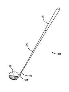
[0046] Referring now to the drawings, wherein like numerals refer to
like parts
throughout the several views, FIG. 1 depicts an embodiment of the present
invention
as a connector 10 that is used to form a releasable connection of a right-
handed club
head 20 to a golf club shaft 30. In FIG. 1, a right-handed golf club 50 is
typically
comprised of a right-handed club head 20, a shaft 30 secured into the right-
handed
club head hosel 24, and a grip 40 secured onto the shaft 30. The right-handed
club
head hosel 24 can be a fixed hosel or an adjustable hosel. The right-handed
club
head 20 can be any type of right-handed club head including a driver club
head, a
woods club head, a hybrid club head, an irons club head, a wedge club head, or
a
putter club head.
[0046] Referring to FIG. 2, an embodiment of the present invention is
shown as the
same connector 10 that is used to form a releasable connection of a left-
handed club
head 21 to a golf club shaft 30. In FIG. 2, a left-handed golf club 51 is
typically
comprised of a left-handed club head 21, a shaft (similar to and depicted as
the shaft
30) secured into the left-handed club head hosel 25, and a grip secured onto
the shaft
(similar to and depicted as the grip 40 secured onto the shaft 30). The left-
handed
club head hosel 25 can be a fixed hosel or an adjustable hosel. The left-
handed club
head 21 can be any type of left-handed club head including a driver club head,
a
woods club head, a hybrid club head, an irons club head, a wedge club head, or
a
putter club head.
[0047] FIG. 3A depicts one aspect of the exemplary connector 10. The
connector
includes a shaft-mount 12, and is shown to have a right-handed head-mount 14.
The right-handed head-mount 14 is adapted to be secured in the right-handed
club
head hosel 24. FIG. 3B depicts another aspect of the exemplary connector 10.
The
connector 10 includes the shaft-mount 12, and is shown to have a left-handed
head-
CA 3126017 2021-07-23
mount 15. The left-handed head-mount 15 is adapted to be secured in the left-
handed club head hosel 25. The shaft-mount 12 includes a shaft-mount bore 32
that is
sized to receive an end portion of the shaft 30. An outer surface 31 of the
shaft 30 is
secured with an adhesive (not shown) within the shaft-mount bore 32. The shaft-
mount 12 further includes a first threaded coupling member in the form of a
shaft or
stem that features external male left-handed threads and right-handed threads
60
intersecting (or overlapping) on the same surface. This threading allows the
shaft-
mount 12 to threadingly mate with the right-handed head-mount 14 or the left-
handed
head-mount 15 to form a releasable connection.
[0048] In FIG. 3A, the right-handed head-mount 14 features female, left-
handed
threads 61 so that the maximum torque on the golf club during a golf swing
tends to
tighten the releasable connection between the shaft-mount 12 and the right-
handed
head-mount 14. The right-handed head-mount 14 incudes a second threaded
coupling
member sized to threadingly mate with the first threaded coupling member to
form a
releasable connection of the right-handed head-mount 14 and shaft-mount 12. In
the
depicted aspect, the second threaded coupling member is a right-handed head-
mount
stem 70, an inner surface of which includes the female, left-handed threads
61, sized
to be securely received within a right-handed club head hosel bore 72, e.g.,
with an
adhesive (not shown). The right-handed head-mount 14 can also include a flange
80.
When the right-handed head-mount 14 is secured to the right-handed club head
hosel
24, a bottom surface 82 of the flange 80 abuts against an upper surface 86 of
the
right-handed club head hosel 24. When the male, intersecting left-handed
threads and
right-handed threads 60 of the shaft-mount 12 mate with the female, left-
handed
threads 61 of the right-handed head-mount 14, an upper surface 84 of the
flange 80
abuts against a bottom surface 88 of the shaft-mount 12. This abutment
prevents axial
and rotational movement between the shaft-mount 12 and the right-handed head-
mount 14.
[0049] Similarly, in FIG. 3B, the left-handed head-mount 15 features
female, right-
handed threads 62 so that the maximum torque on the golf club during a golf
swing
tends to tighten the releasable connection between the shaft-mount 12 and the
left-
11
CA 3126017 2021-07-23
, .
handed head-mount 15. The left-handed head-mount 15 incudes a second threaded
coupling member sized to threadingly mate with the first threaded coupling
member to
form a releasable connection of the left-handed head-mount 15 and shaft-mount
12.
A left-handed head-mount stem 71 (i.e., the second threaded coupling member)
of the
left-handed head-mount 15, an inner surface of which includes the female,
right-
handed threads 62, is sized to be securely received within a left-handed club
head
hosel bore 73, e.g., with an adhesive (not shown). The left-handed head-mount
15
can also include a flange 81. When the left-handed head-mount 15 is secured to
the
left-handed club head hosel 25, a bottom surface 83 of the flange 81 abuts
against an
upper surface 87 of the left-handed club head hose! 25. When the male,
intersecting
left-handed threads and right-handed threads 60 of the shaft-mount 12 mate
with the
female, right-handed threads 62 of the left-handed head-mount 15, an upper
surface
85 of the flange 81 abuts against the bottom surface 88 of the shaft-mount 12.
This
abutment prevents axial and rotational movement between the shaft-mount 12 and
the
left-handed head-mount 15.
[0050] FIGS. 3C and 3D depict another aspect of the exemplary
connector 10. The
connector 10 includes the shaft-mount 12 having the male, intersecting left-
handed
and right-handed threads 60, and a universal head-mount 114. The universal
head-
mount 114 is adapted be secured within the right-handed club head hosel 24 or
the
left-handed club head hose! 25. The depicted universal head-mount 114 includes
a
second threaded coupling member in the form of a head-mount stem, an inner
surface
of which includes female, intersecting (or overlapping) left-handed threads
and right-
handed threads 161. The female, intersecting left-handed and right-handed
threads
161 threadingly mate with the first threaded coupling member (i.e., the male,
intersecting left-handed and right-handed threads 60) to form a releasable
connection
of the universal head-mount 114 and shaft-mount 12. Therefore, the shaft-mount
12
can threadingly mate with the universal head-mount 114 by either right-handed
thread
convention or left-handed thread convention. As such, a single head-mount and
a
single shaft-mount can be used for left-handed club heads or right-handed club
heads.
12
CA 3126017 2021-07-23
[0051] FIG. 4A depicts another aspect of the exemplary connector 10. The
connector 10 includes a shaft-mount 13, and is shown to have a right-handed
head-
mount 16 that is intended to be secured into the right-handed club head hosel
24.
FIG. 4B depicts another aspect of the exemplary connector 10, wherein the
connector
includes the shaft-mount 13, and is shown to have a left-handed head-mount 17
that is intended to be secured in the left-handed club head hosel 25. The
shaft-mount
13 includes a first threaded coupling member in the form of a threaded shaft
or stem
64. The threaded stem 64 includes a first section formed with male, right-
handed
threads 68 and a second section formed with male, left-handed threads 69. The
first
and second sections are axially spaced such that male, right-handed threads 68
and
male, left-handed threads 69 are staggered on the stem 65 (i.e., the male,
right-
handed threads 68 and male, left-handed threads 69 are not intersecting or
overlapping on stem 64). It should be appreciated that the major diameter of
the
male, right-handed threads 68 can differ from the major diameter of the male,
left-
handed threads 69.
[0052] In FIG. 4A, the right-handed head-mount 16 includes a second
threaded
coupling member in the form of a stem or sleeve having an inner surface
defining a
bore sized and dimensioned to receive the threaded stem 64 of the shaft-mount
13.
The inner surface includes a first section corresponding the first section of
the stem 64
and a second section corresponding with the second section of the stem 64. The
first
section of the inner surface is substantially smooth (i.e., devoid of threads)
to avoid
engagement with the male, right-handed threads 68 of the stem 64. The male,
left-
handed threads 69 of the stem mate with female, left-handed threads 67 formed
on
the second section of the inner surface to form a releasable connection
between the
shaft-mount 13 and the right-handed head-mount 16. And the threading
engagement
between the male, left-handed threads 69 and the female, left-handed threads
67
ensures that the maximum torque on the golf club during a golf swing tends to
tighten
the releasable connection between the shaft-mount 13 and the right-handed head-
mount 16.
13
CA 3126017 2021-07-23
[0053] Similarly, in FIG. 4B the left-handed head-mount 17 includes a
second
threaded coupling member in the form of a stem or sleeve having an inner
surface
defining a bore sized and dimensioned to receive the threaded stem 64 of the
shaft-
mount 13. The inner surface includes a first section corresponding the first
section of
the stem 64 and a second section corresponding with the second section of the
stem
64. The second section of the inner surface is substantially smooth (i.e.,
devoid of
threads) to avoid engagement with the male, left-handed threads 69 of the stem
64.
The male, right-handed threads 68 of the stem mate with female, right-handed
threads
66 formed on the first section of the inner surface to form a releasable
connection
between the shaft-mount 13 and the left-handed head-mount 17. And the
threading
engagement between the male, right-handed threads 68 and the female, right-
handed
threads 66 ensures that the maximum torque on the golf club during a golf
swing
tends to tighten the releasable connection between the shaft-mount 13 and the
left-
handed head-mount 17.
[0054] Regarding the embodiment of FIGS. 4A and 4B, it should be
appreciated
that the order of staggered right-handed threads 68 and left-handed threads 69
on the
threaded stem 64 of the shaft-mount 13 can be reversed. Accordingly, the order
of the
female, left-handed threads 67 and female, right-handed threads 66 on the
respective
right-handed head-mount 16 and the left-handed head-mount 17 can be reversed.
[0055] FIG. 5A depicts another aspect of the exemplary connector 10. The
connector 10 includes a shaft-mount 11 and a right-handed head-mount 18 that
is
adapted to be secured into a right-handed club head hose! 24. FIG. 5B depicts
another aspect of the exemplary connector 10 including the shaft-mount 11 and
a left-
handed head-mount 19 that is intended to be secured in a left-handed club head
hosel
25. The shaft-mount 11 includes a first threaded coupling member in the form
of a
threaded stem or sleeve 94 having an outer surface and an inner surface
defining a
bore. The outer surface of the stem 94 includes male, right-handed threads 96
and
the inner surface of the stem 94 includes female, left-handed threads 95. The
male,
right-handed threads 96 and the female, left-handed threads 95 are arranged
concentric to one another.
14
CA 3126017 2021-07-23
. .
[0056] In FIG. 5A, the right-handed head-mount 18 includes a second
threaded
coupling member featuring a shaft formed with male, left-handed threads 97 so
that
the maximum torque on the golf club during a golf swing tends to tighten the
releasable connection between the shaft-mount 11 and the right-handed head-
mount
18. The female, left-handed threads 95 on the inner surface of the stem 94
mate with
the male, left-handed threads 97 to form a releasable connection between the
shaft-
mount 11 and the right-handed head-mount 18.
[0057] In FIG. 56, the left-handed head-mount 19 includes a second
threaded
coupling member featuring a stem or sleeve having an inner surface formed with
female, right-handed threads 98 so that the maximum torque on the golf club
during a
golf swing tends to tighten the releasable connection between the shaft-mount
11 and
the left-handed head-mount 19. The male, right-handed threads 96 on the outer
surface of the stem 94 mate with the female, right-handed threads 98 to form a
releasable connection between the shaft-mount 11 and the left-handed head-
mount
19.
[0058] It should be appreciated that the order of the concentric right-
handed
threads 96 and left-handed threads 95 on the stem 94 can be reversed.
Accordingly,
the right-handed head-mount 18 would change to resemble the shape of the left-
handed head-mount 19 depicted in FIG. 5B, and feature female, left-handed
threads.
And the left-handed head-mount 19 would change to resemble the shape of the
right-
handed head-mount 18 depicted in FIG. 5A, and feature male, right-handed
threads.
Further, the right-handed and left-handed head-mounts 18, 19 are shown in
FIGS. 5A
and 5B without a flange to abut against the shaft-mount 11. As such, the
bottom
surface of the shaft-mount 11 would abut against the upper surface of each
hosel 24,
25 of the club head to prevent axial and rotational movement between the shaft-
mount
and respective head-mount. In similar embodiments, a flange can be featured on
one
or both head-mounts to abut against the shaft-mount.
[0059] FIGS. 6A and 6B depict another aspect of the exemplary connector
10. The
connector 10 includes a shaft-mount 112 having a first threaded coupling
member in
the form of a shaft or stem that features external male left-handed threads
and right-
CA 3126017 2021-07-23
handed threads 160 intersecting (or overlapping) on the same surface. In FIG.
6A, a
right-handed club head hosel 24 includes a second threaded coupling member
sized
to threadingly mate with the first threaded coupling member to form a
releasable
connection of the right-handed club head hosel 24 and shaft-mount 112. The
second
threaded coupling member features female, left-handed threads 164 so that the
maximum torque on the golf club during a golf swing tends to tighten the
releasable
connection between the shaft-mount 112 and the right-handed club-head hosel
24.
Similarly, in FIG. 6B a left-handed club head hosel 25 includes a second
threaded
coupling member sized to threadingly mate with the first threaded coupling
member to
form a releasable connection of the left-handed club head hosel 25 and shaft-
mount
112. The second threaded coupling member features female, right-handed threads
165 so that the maximum torque on the golf club during a golf swing tends to
tighten
the releasable connection between the shaft-mount 112 and the left-handed club-
head
hose! 25.
[0060]
FIG. 7A depicts another aspect of the exemplary connector 10. The
connector 10 includes a shaft-mount 212 and a right-handed head-mount 214
adapted
to be secured in a right-handed club head hosel 24. The shaft-mount 212
includes a
first threaded coupling member defined by an inner surface having intersecting
(or
overlapping) female left-handed threads and right-handed threads 224. As
shown, the
inner surface defines a threaded bore. In FIG. 7A, the right-handed head-mount
214
incudes a second threaded coupling member sized to threadingly mate with the
first
threaded coupling member to form a releasable connection of the right-handed
head-
mount 214 and shaft-mount 212. In the depicted aspect, the right-handed head-
mount 214 features a stem sized to be received within the threaded bore of the
shaft-
mount 212. The stem is formed with male, left-handed threads 225 which mate
with
the intersecting (or overlapping) female left-handed threads and right-handed
threads
224 so that the maximum torque on the golf club during a golf swing tends to
tighten
the releasable connection between the shaft-mount 212 and the right-handed
head-
mount 214.
16
CA 3126017 2021-07-23
[0061] FIG. 7B depicts another aspect of the exemplary connector 10 wherein
the
connector 10 includes the shaft-mount 212 and a left-handed head-mount 215
adapted to be secured in a left-handed club head hosel 25. In FIG. 7B, the
left-handed
head-mount 215 incudes a second threaded coupling member sized to threadingly
mate with the first threaded coupling member to form a releasable connection
of the
left-handed head-mount 215 and shaft-mount 212. In the depicted aspect, the
left-
handed head-mount 215 features a stem sized to be received within the threaded
bore of the shaft-mount 212. The stem is formed with male, right-handed
threads 226
which mate with the intersecting (or overlapping) female left-handed threads
and right-
handed threads 224 so that the maximum torque on the golf club during a golf
swing
tends to tighten the releasable connection between the shaft-mount 212 and the
left-
handed head-mount 215.
[0062] FIGS. 7C and 7D depict another aspect of the exemplary connector 10
wherein the connector 10 includes the shaft-mount 212 and a universal head-
mount
216 adapted be secured within the right-handed club head hosel 24 or left-
handed
club head hose! 25. The universal head-mount 216 incudes a second threaded
coupling member sized to threadingly mate with the first threaded coupling
member to
form a releasable connection of the universal head-mount 216 and shaft-mount
212.
In the depicted aspect, the universal head-mount 216 features a stem sized to
be
received within the threaded bore of the shaft-mount 212. The stem is formed
with
male, intersecting (or overlapping) left-handed and right-handed threads 228
which
mate with the intersecting (or overlapping) female, left-handed and right-
handed
threads 224 of the shaft-mount 212. Therefore, the shaft-mount 212 can
threadingly
mate with the universal head-mount 216 by either right-handed thread
convention or
left-handed thread convention. As such, a single head-mount and a single shaft-
mount
can be used for left-handed club heads or right-handed club heads.
[0063] FIG. 8A depicts another aspect of the exemplary connector 10. The
connector 10 includes a shaft-mount 232 and a right-handed head-mount 252
adapted
to be secured in a right-handed club head hosel 24. The shaft-mount 232
includes an
inner surface defining a threaded bore. A stem is provided within the threaded
bore,
17
CA 3126017 2021-07-23
with an outer surface of the stem spaced radially inward of the inner surface
relative to
a center axis of the shaft-mount. The inner surface defining the threaded bore
features female, left-handed threads 234, and the outer surface of the stem
features
male, right-handed threads 235. The threads 234, 235 together define a first
threaded
coupling member of the shaft-mount 232.
[0064] In FIG. 8A, the right-handed head-mount 252 incudes a second
threaded
coupling member sized to threadingly mate with the first threaded coupling
member to
form a releasable connection of the right-handed head-mount 252 and shaft-
mount
232. As depicted, the second threaded coupling member includes a stem or
sleeve
sized to be received in the threaded bore of the shaft-mount 232, the sleeve
having an
outer surface and an inner surface defining a bore sized to receive the stem
of the
shaft-mount 232. The outer surface features male, left-handed threads 253 and
the
inner surface 254 is substantially smooth (i.e. devoid of threads) to avoid
engagement
with the male, right-handed threads 235 of the shaft-mount 232. The male, left-
handed
threads 253 threadingly engage the female, left-handed threads 234 so that the
maximum torque on the golf club during a golf swing tends to tighten the
releasable
connection between the shaft-mount 232 and the right-handed head-mount 252.
[0065] FIG. 8B depicts another aspect of the exemplary connector 10 wherein
the
connector 10 includes the shaft-mount 232, and a left-handed head-mount 255
adapted to be secured in a left-handed club head hosel 25. The left-handed
head-
mount 255 includes a second threaded coupling member sized to threadingly mate
with the first threaded coupling member to form a releasable connection of the
left-
handed head-mount 255 and shaft-mount 232. As depicted, the second threaded
coupling member includes a stem or sleeve sized to be received in the threaded
bore
of the shaft-mount 232, the sleeve having an outer surface 257 and an inner
surface
defining a bore sized to receive the stem of the shaft-mount 232. The outer
surface
257 is substantially smooth (i.e. devoid of threads) to avoid engagement with
the
female, left-handed threads 234 of the shaft-mount 232. The inner surface is
formed
with female, right-handed threads 256 which threadingly engage the male, right-
handed threads 235 of the shaft-mount 232 so that the maximum torque on the
golf
18
CA 3126017 2021-07-23
. .
club during a golf swing tends to tighten the releasable connection between
the shaft-
mount 232 and the left-handed head-mount 255.
[0066] It should be appreciated that the order of the right-handed
threads 235 and
left-handed threads 234 of the shaft-mount 232 can be reversed on the shaft-
mount
232. Accordingly, the order and location of the right-handed threads 256 and
left-
handed threads 253 of the respective left-handed head-mount 255 and right-
handed
head-mount 252 can be reversed.
[0067] FIG. 9A depicts another aspect of the exemplary connector 10.
The
connector 10 includes a shaft-mount 262 and a right-handed head-mount 272 that
is
adapted to be secured into a right-handed club head hosel 24. The shaft-mount
262
includes a first threaded coupling member in the form of a stem or sleeve
having an
outer surface and an inner surface defining a threaded bore. The inner surface
of the
stem includes a first section with female, left-handed threads 263 and a
second
section with female, right-handed threads 264. The first and second sections
are
axially spaced such that female, right-handed threads 264 and female, left-
handed
threads 263 are staggered on the inner surface of the threaded bore (i.e., the
female,
right-handed threads 264 and female, left-handed threads 263 are not
intersecting or
overlapping on the inner surface of the stem). Further, the diameter of the
first section
with the female, right-handed threads 264 differs from the diameter of the
second
section with the female, left-handed threads 263.
[0068] In FIG. 9A, the right-handed head-mount 272 includes a second
threaded
coupling member in the form of a stem having an outer surface with male, left-
handed
threads 273. The male, left-handed threads 273 mate with female, left-handed
threads 263 to form a releasable connection between the shaft-mount 262 and
the
right-handed head-mount 272. And the threading engagement between the male,
left-
handed threads 273 and the female, left-handed threads 263 ensures that the
maximum torque on the golf club during a golf swing tends to tighten the
releasable
connection between the shaft-mount 262 and the right-handed head-mount 272.
[0069] FIG. 9B depicts another aspect of the exemplary connector 10
wherein the
connector 10 includes the shaft-mount 262 and a left-handed head-mount 275
that is
19
CA 3126017 2021-07-23
adapted to be secured into a left-handed club head hosel 25. The left-handed
head-
mount 275 includes a second threaded coupling member in the form of a stem
having
an outer surface with male, right-handed threads 276. The threaded stem of the
head-
mount 275 is sized to be received in the threaded bore of the shaft-mount 262.
The
size and dimensions of the threaded stem of the head-mount 275 are such that
they
avoid engagement with the female, left-handed threads 263 on the first section
of the
inner surface of the threaded bore of the shaft-mount 262. The male, right-
handed
threads 276 mate with female, right-handed threads 264 to form a releasable
connection between the shaft-mount 262 and the left-handed head-mount 275. And
the threading engagement between the male, right-handed threads 276 and the
female, right-handed threads 264 ensures that the maximum torque on the golf
club
during a golf swing tends to tighten the releasable connection between the
shaft-
mount 262 and the left-handed head-mount 275.
[0070] It
should be appreciated that the order of staggered female, right-handed
threads 264 and female, left-handed threads 263 on the shaft-mount 262 can be
reversed. Accordingly, the right-handed head-mount 272 would change to
resemble
the shape of the left-handed head-mount 275 depicted in FIG. 9B, with male,
left-
handed threads. And the left-handed head-mount 275 would change to resemble
the
shape of the right-handed head-mount 272 depicted in FIG. 9A, with male, right-
handed threads.
[0071] In
yet another embodiment, certain of the shaft-mounts described above
can include a stem to secure within a bore of the shaft 30.
[0072] In
yet another embodiment, certain of the right-handed or left-handed head-
mounts described above can include a bore to secure onto a stem of the
respective
right-handed or left-handed hosel 24, 25 of an associated club head.
[0073] It
will be appreciated that the above-disclosed embodiments and other
features and functions, or alternatives or varieties thereof, may be desirably
combined
into many other different systems or applications. Also that various presently
unforeseen or unanticipated alternatives, modifications, variations or
improvements
CA 3126017 2021-07-23
therein may be subsequently made by those skilled in the art which are also
intended
to be encompassed by the following claims.
21
CA 3126017 2021-07-23