Note: Descriptions are shown in the official language in which they were submitted.
CA 03126197 2021-07-08
WO 2020/164881
PCT/EP2020/051684
TITLE
Apparatus for extracorporeal treatment of blood and method for determining a
parameter
indicative of the progress of an extracorporeal blood treatment.
DESCRIPTION
The invention relates to an apparatus for extracorporeal treatment of blood
and a method for determining
a parameter indicative of the progress of an extracorporeal blood treatment
(referred to as effectiveness
parameter), in particular a purification treatment whose purpose is to
alleviate renal insufficiency, such
as - without limitation - hemodialysis or hemodiafiltration. It is also
disclosed a method of determining
said parameter indicative of the progress of an extracorporeal blood
treatment. For instance, the
parameter may be one of:
- the concentration in the blood of a given solute (for example, sodium),
- the actual dialysance D or the actual clearance K of the exchanger for a
given solute (the dialysance D
and the clearance K representing the purification efficiency of the
hemodialyzer or hemofilter used in
the blood treatment),
.. - the dialysis dose administered after a treatment time t, which, according
to the work of Sargent and
Gotch, may be linked to the dimensionless ratio Kt/V, where K is the actual
clearance in the case of
urea, t the elapsed treatment time and V the volume of distribution of urea,
i.e. the total volume of water
in the patient (Gotch F. A. and Sargent S. A., "A mechanistic analysis of the
National Cooperative
Dialysis Study (NCDS)", Kidney Int. 1985, Vol. 28, pp. 526-34). The dialysis
dose ¨ as above defined
¨ is an integrated value K(t)dtN across a time interval, e.g. the dose after
treatment time tn is the integral
from the beginning of treatment until time instant tn.
In an haemodialysis treatment a patient's blood and a treatment liquid
approximately (but not
necessarily) isotonic with blood flow are circulated in a respective
compartment of haemodialyser, so
that, impurities and undesired substances present in the blood (urea,
creatinine, etc.) may migrate by
diffusive transfer from the blood into the treatment liquid. The ion
concentration of the treatment liquid
is chosen so as to correct the ion concentration of the patient's blood. In a
treatment by
haemodiafiltration, a convective transfer by ultrafiltration, resulting from a
positive pressure difference
created between the blood side and the treatment-liquid side of the membrane
of a haemodiafilter, is
added to the diffusive transfer obtained by dialysis.
.. It is of interest to be able to determine, throughout a treatment session,
one or more parameters indicative
of the progress of the treatment so as to be able, where appropriate, to
modify the treatment conditions
that were initially fixed or to at least inform the patient and the medical
personnel about the effectiveness
of the treatment. The knowledge of one or more of the following parameters may
make it possible to
follow the progress of the treatment, and for instance may allow assessing the
suitability of the initially
fixed treatment conditions:
- concentration in the blood of a given solute (for example, sodium),
1
CA 03126197 2021-07-08
WO 2020/164881
PCT/EP2020/051684
- actual dialysance D or the actual clearance K of the exchanger for solute
(the dialysance D and the
clearance K representing the purification efficiency of the exchanger),
- dialysis dose administered after a treatment time Kt/V, where K is the
actual clearance in the case of
urea, t the elapsed treatment time and V the volume of distribution of urea.
The determination of these parameters requires precise knowledge of a physical
or chemical
characteristic of the blood. As it can be understood, determination of this
characteristic cannot in practice
be obtained by direct measurement on a specimen for therapeutic, prophylactic
and financial reasons.
Indeed, it is out of the question taking - in the course of a treatment -
multiple specimens necessary to
monitor the effectiveness of the treatment from a patient who is often anemic;
furthermore, given the
risks associated with handling specimens of blood which may possibly be
contaminated, the general
tendency is to avoid such handling operations; finally, laboratory analysis of
a specimen of blood is both
expensive and relatively lengthy, this being incompatible with the desired
objective of knowing the
effectiveness of a treatment while the treatment is still ongoing.
Several methods have been proposed for in vivo determining haemodialysis
parameters without having
to take measurements on blood samples. Document EP 0547025 describes a method
for determining the
concentration of a substance, such as sodium, in a patient's blood subjected
to a haemodialysis treatment.
This method also makes it possible to determine the dialysance D - for example
for sodium - of the
haemodialyser used. The method comprises the steps of circulating a first and
a second haemodialysis
liquids having different sodium concentrations in succession through the
haemodialyser, measuring the
conductivity of the first and second dialysis liquids upstream and downstream
of the haemodialyser, and
computing the concentration of sodium in the patient's blood (or the
dialysance D of the haemodialyser
for sodium) from the values of the conductivity of the liquid which are
measured in the first and second
dialysis liquids upstream and downstream of the haemodialyser. Document EP
0658352 describes
another method for the in vivo determination of haemodialysis parameters,
which comprises the steps
of: making at least a first and a second treatment liquids, having a
characteristic (the conductivity, for
example) associated with at least one of the parameters (the ion concentration
of the blood, the
dialysance D, the clearance K, Kt/V, for example) indicative of the treatment,
flow in succession through
the haemodialyser, the value of the characteristic in the first liquid
upstream of the exchanger being
different from the value of the characteristic in the second liquid upstream
of the hemodialyzer;
measuring, in each of the first and second treatment liquids, two values of
the characteristic, respectively
upstream and downstream of the hemodialyzer; making a third treatment liquid
flow through the
hemodialyzer while the characteristic of the second liquid has not reached a
stable value downstream of
the hemodialyzer, the value of the characteristic in the third liquid upstream
of the hemodialyzer being
different from the value of the characteristic in the second liquid upstream
of the hemodialyzer;
measuring two values of the characteristic in the third liquid, respectively
upstream and downstream of
the hemodialyzer; and computing at least one value of at least one parameter
indicative of the progress
2
CA 03126197 2021-07-08
WO 2020/164881
PCT/EP2020/051684
of the treatment from the measured values of the characteristic in the first,
second and third treatment
liquids. Another method for the in vivo determination of the haemodialysis
parameters which does not
require taking measurements on blood samples is described in document EP
0920877. This method
includes the steps of: making a treatment liquid flow through the exchanger,
this treatment liquid having
a characteristic which has an approximately constant nominal value upstream of
the exchanger; varying
the value of the characteristic upstream of the exchanger and then re-
establishing the characteristic to
its nominal value upstream of the exchanger; measuring and storing in memory a
plurality of values
adopted by the characteristic of the treatment liquid downstream of the
exchanger in response to the
variation in the value of this characteristic caused upstream of the
exchanger; determining the area of a
.. downstream perturbation region bounded by a baseline and a curve
representative of the variation with
respect to time of the characteristic; and computing the parameter indicative
of the effectiveness of a
treatment from the area of the downstream perturbation region and from the
area of an upstream
perturbation region bounded by a baseline and a curve representative of the
variation with respect to
time of the characteristic upstream of the exchanger. Document EP2732834
describes an apparatus for
extracorporeal treatment of blood comprising a control unit which is
configured to calculate values of a
parameter relating to treatment effectiveness based on measures of the
conductivity in the spent dialysate
line. The value of the effectiveness parameter is calculated using one or more
values representative of
the conductivity in the spent dialysate line obtained relying on a
mathematical model. The control unit
causes an upstream (with respect to the treatment unit) variation of the value
of a characteristic Cdin in
the fresh treatment liquid with respect to a prescription baseline Cdset and
then re-establishes the
characteristic Cdin in the fresh treatment liquid to said prescription
baseline Cdset. The upstream variation
causes a corresponding and timely delayed downstream (with respect to the
treatment unit) variation of
the same characteristic Cdout in the spent liquid flowing in the spent
dialysate line. The control unit is
configured to receive at least one parametric mathematical model, which puts
into relation the
characteristic Cdin in the fresh treatment liquid with the characteristic
Cdout in the spent liquid. In order
to determine the parameters of the parametric mathematical model, the control
unit is configured to
receive, e.g. from a sensor, measures of a plurality of values taken by a
reference portion of the
downstream variation of the characteristic Cdout in the spent liquid, wherein
the reference portion, which
is used by the control unit to characterize the mathematical model, has a
duration ATR significantly
.. shorter than an entire duration AT of the downstream variation. The above
described methods require
a relatively short - compared to treatment time - modification of the value of
a characteristic of the
dialysis liquid (the conductivity, for example) and then the re-establishment
of this characteristic to its
initial value, which is generally the prescribed value. Since, deviations from
the prescription are not
desirable and since the above described methods require a minimum duration of
the introduced
modification, it derives that all these methods can be carried out only few
times during a treatment.
Document US 2001004523 describes a solution for continuously determining a
parameter (D, Cbin, K,
3
CA 03126197 2021-07-08
WO 2020/164881
PCT/EP2020/051684
Kt/V) indicative of the effectiveness of an extracorporeal blood treatment
comprising the steps of:
causing a succession of sinusoidal variations in the characteristic (Cd) a
treatment liquid upstream of
the exchanger, continuously storing in memory a plurality of values (Cdmi . .
. Cd mi . . . Cd) of the
characteristic (Cd) upstream of the exchanger, measuring and continuously
storing in memory a plurality
of values (Cdopu . . . Cdopti . . Cd) adopted by the characteristic (Cd)
downstream of the exchanger
in response to the variations in the characteristic (Cd) which are caused
upstream of the exchanger,
computing - each time that a predetermined number of new values (Cdpmj) of the
characteristic (Cd)
downstream of the exchanger has been stored - a parameter (D, Cbin, K, Kt/V)
indicative of the
effectiveness of the extracorporeal blood treatment, from a first series of
values (Cdmj) of the
characteristic (Cd) upstream of the exchanger, from a second series of values
(Cdpmj) of the characteristic
(Cd) downstream of the exchanger. Another apparatus and method for determining
a parameter
indicative of the progress of an extracorporeal blood treatment is disclosed
in document EP2687248,
which describes an apparatus for extracorporeal treatment of blood wherein a
control unit is configured
to calculate values of a parameter relating to treatment effectiveness based
on measures of the
conductivity in the spent dialysate line subsequent to an alternating
conductivity perturbation
continuously imposed on the preparation line of fresh dialysis fluid. The
control unit is configured to
cause a plurality of consecutive and continuously repeated variations Vk of
the characteristic Cd around
the prescription baseline Cdsm in the liquid flowing in the preparation line.
The variations define for
instance a square wave around the prescription baseline. The above methods,
which require a continuous
perturbation in the characteristic of the treatment liquid, prevent execution
of tasks, other than the one
for measuring the effectiveness parameter, which may affect the concerned
characteristic
(conductivity/concentration) of the dialysis fluid. Indeed, while the control
system is executing the
effectiveness parameter detection, the control system will not execute other
tasks taking an active control
on the conductivity/composition of the dialysis liquid (e.g. tasks acting on
the sodium concentration of
the dialysis liquid in response to detection of certain parameters such as
blood concentration).
Furthermore, the system dynamic may depend on the working conditions, like
dialysis fluid flow and
dialyzer type and the system is not always able to converge to a meaningful
solution. In some cases,
with low dialysis fluid flows and filters with large areas (or vice versa) the
measure could fail.
It is therefore an object of the present invention to provide an apparatus and
a method configured to
reliably calculate an effectiveness parameter one or more times during
treatment without substantially
impairing on prescription delivered to the patient and minimally affecting the
operation flexibility of the
blood treatment apparatus. In particular, it is an object to tune and optimize
said method and an apparatus
configured to calculate the effectiveness parameter even just one time without
substantially impairing
on prescription delivered to the patient. Additionally, it is an object
providing a method and an apparatus
which may be implemented with no need of high computational power and time
machine. Another
auxiliary object is an apparatus capable of operating in a safe manner. A
further auxiliary object is an
4
CA 03126197 2021-07-08
WO 2020/164881
PCT/EP2020/051684
apparatus capable of automatically calculate the effectiveness parameter and
inform the operator
accordingly.
SUMMARY
At least one of the above objects is substantially reached by an apparatus
according to one or more of
the appended claims. Apparatus and methods according to aspects of the
invention and capable of
achieving one or more of the above objects are here below described.
A 1st aspect concerns an apparatus for extracorporeal treatment of blood
comprising:
a blood treatment unit having a primary chamber and a secondary chamber
separated by a semi-
permeable membrane;
a preparation line having one end connected to an inlet of a secondary chamber
of the treatment unit and
configured to convey fresh treatment liquid to the secondary chamber, the
fresh treatment liquid
presenting a characteristic which is one selected in the group of:
conductivity in the fresh treatment liquid, and
concentration of at least one substance in the fresh treatment liquid,
a spent dialysate line having one end connected to an outlet of said secondary
chamber and configured
to remove spent liquid from the secondary chamber, the spent liquid presenting
a characteristic which
is one selected in the group of:
conductivity in the spent liquid, and
concentration of at least one substance in the spent liquid,
a control unit configured for commanding execution of a task for determination
of a parameter indicative
of the effectiveness of the extracorporeal blood treatment, said task
comprising the following steps:
- receiving at least one prescription baseline for the characteristic in
the fresh treatment liquid;
- causing fresh treatment liquid to flow in the preparation line to the
secondary chamber with the
characteristic being at said prescription baseline;
- causing spent liquid to flow out of the secondary chamber into the spent
dialysate line;
- causing an upstream variation of the value of the characteristic in the
fresh treatment liquid with
respect to said prescription baseline thereby causing a corresponding and
timely delayed
downstream variation of the same characteristic in the spent liquid flowing in
the spent dialysate
line; wherein the upstream variation has an amplitude (e.g., an absolute value
variation of the
characteristic) and a duration over time;
- computing at least one value of a parameter indicative of the
effectiveness of the extracorporeal
blood treatment by using values correlated to the upstream variation of the
value of the
characteristic in the fresh treatment liquid and values correlated to the
downstream variation of
the same characteristic in the spent liquid; optionally said values correlated
to the upstream
variation being set and/or measured and said values correlated to the
downstream variation
being measured and/or computed;
5
CA 03126197 2021-07-08
WO 2020/164881
PCT/EP2020/051684
wherein said task further comprises:
- receiving a flow rate, or a parameter/parameters correlated to the flow
rate, of the fresh treatment
liquid in the preparation line;
- computing said amplitude and/or said duration over time of the upstream
variation to be caused
as a function of the flow rate or of the parameter correlated to the flow
rate.
It is noted that having knowledge of the effluent flow rate and of the
ultrafiltration flow rate is equivalent
to knowing the flow rate of the fresh treatment liquid in the preparation line
in a hemodialysis treatment;
in an HDF treatment, knowledge of the effluent flow rate, infusion flow rate
and of the ultrafiltration
flow rate is equivalent to knowing the flow rate of the fresh treatment liquid
in the preparation line.
It is also noted that the flow rate in the preparation line may be the set
flow rate or a measured flow rate
in the preparation line (if relevant, the same applies to the other mentioned
flow rates, namely effluent
flow rate, infusion flow rate, ultrafiltration flow rate).
In an additional aspect, the control unit execute the task including receiving
a blood or plasma flow rate
at the inlet of the primary chamber (e.g., set or measured blood/plasma flow
rate) and including
computing said amplitude and/or said duration over time of the upstream
variation to be caused as a
function of the blood or plasma flow rate, the computing of the amplitude
and/or said duration over time
of the upstream variation being made either as a function of both the flow
rate (or of the parameter
correlated to the flow rate) of the fresh treatment liquid in the preparation
line and the blood (or plasma)
flow rate, or as a function of the blood (or plasma) flow rate.
.. In an additional aspect, the control unit execute the task including
receiving an efficiency parameter of
the blood treatment unit, such as clearance or dialysance or mass transfer
area coefficient KoA, and
including computing said amplitude and/or said duration over time of the
upstream variation to be
caused as a function of the efficiency parameter of the blood treatment unit,
the computing of the
amplitude and/or said duration over time of the upstream variation being made
as a function of anyone
of (let alone or in any combination) the flow rate (or of the parameter
correlated to the flow rate) of the
fresh treatment liquid in the preparation line, the blood (or plasma) flow
rate and/or the efficiency
parameter of the blood treatment unit. The efficiency parameter may be
received from a memory or an
input device of the apparatus, or may be calculated.
In a 2nd aspect according to the 1st aspect/previous aspects, the amplitude
and/or the duration over time
are/is higher if the flow rate of the fresh treatment liquid is lower and
wherein the amplitude and/or the
duration over time are/is lower if the flow rate of the fresh treatment liquid
(and/or the blood or plasma
flow rate) is higher.
In another aspect according to anyone of the previous aspects, the computed
duration over time being
between 50 s (being in particular a prefixed minimum duration over time) and
200 s (being in particular
a prefixed maximum duration over time), optionally between 90 s and 150 s.
In another aspect according to anyone of the previous aspects, the
characteristic is the conductivity in
6
CA 03126197 2021-07-08
WO 2020/164881
PCT/EP2020/051684
the fresh liquid and, optionally, the computed amplitude of conductivity being
between 0.4 mS/cm
(milliSiemens/centimeter) and 1.1 mS/cm, optionally between 0.5 mS/cm and 1
mS/cm (absolute
values).
In another aspect according to anyone of the previous aspects, the flow rate
of the fresh treatment liquid
is lower than a prefixed maximum flow rate, being at most 850 ml/min, in
particular the flow rate of the
fresh treatment liquid being between 250 ml/min and 850 ml/min, optionally
between 300 ml/min and
800 ml/min. The prefixed minimum flow rate of the fresh treatment liquid being
for example 200
ml/min, or 300 ml/min.
In a 3rd aspect according to any one of the preceding aspects, the amplitude
and/or the duration over
time are/is inversely proportional with respect to the flow rate of the fresh
treatment liquid (and/or the
blood or plasma flow rate).
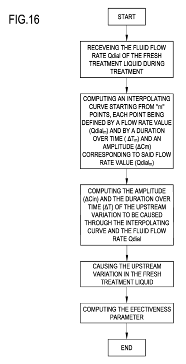
In a 4th aspect according to any one of the preceding aspects, computing the
amplitude and/or the
duration over time is performed through at least one mathematical formula;
wherein optionally the
mathematical formula is an interpolating curve; wherein optionally the
interpolating curve is computed
starting from "m" points, each point being defined by a flow rate value of the
fresh treatment liquid and
by a duration over time value and/or by an amplitude value corresponding to
said flow rate value;
wherein optionally "m" is equal to or greater than two.
In a 5th aspect according to any one of the preceding aspects, computing the
amplitude and/or the
duration over time is a function of a prefixed maximum flow rate of the fresh
treatment liquid. The
prefixed maximum flow rate of the fresh treatment liquid may be received from
a memory or an input
device of the apparatus, or may be calculated, based on e.g., an apparatus set-
up.
In a further aspect according to any one of the preceding aspects, computing
the amplitude and/or the
duration over time is a function of a difference between the flow rate of the
fresh treatment liquid and a
prefixed maximum flow rate of the fresh treatment liquid. In particular, the
difference between the flow
rate of the fresh treatment liquid and a prefixed maximum flow rate of the
fresh treatment liquid being
multiplied by a multiplying factor.
In a further aspect according to any one of the preceding aspects, computing
the amplitude and/or the
duration over time is a function of a prefixed minimum flow rate of the fresh
treatment liquid. The
prefixed minimum flow rate of the fresh treatment liquid may be received from
a memory or an input
device of the apparatus, or may be calculated, based on e.g., an apparatus set-
up.
In a further aspect according to any one of the preceding aspects, computing
the amplitude and/or the
duration over time is a function of a difference between a prefixed minimum
flow rate of the fresh
treatment liquid and the flow rate of the fresh treatment liquid. In
particular, the prefixed minimum flow
rate of the fresh treatment liquid and the flow rate of the fresh treatment
liquid being multiplied by a
multiplying factor.
7
CA 03126197 2021-07-08
WO 2020/164881
PCT/EP2020/051684
In a further aspect according to any one of the preceding aspects, computing
the amplitude and/or the
duration over time is a function of a difference between a prefixed maximum
flow rate of the fresh
treatment liquid and a prefixed minimum flow rate of the fresh treatment
liquid.
In a further aspect according to any one of the preceding aspects, computing
the amplitude and/or the
duration over time is a function of a prefixed maximum duration over time, in
particular corresponding
to a minimum flow rate of the apparatus. The prefixed maximum duration over
time may be received
from a memory or an input device of the apparatus, or may be calculated, based
on e.g., an apparatus
set-up.
In a further aspect according to any one of the preceding aspects, computing
the amplitude and/or the
duration over time is a function of a prefixed minimum duration over time, in
particular corresponding
to a maximum flow rate of the apparatus. The prefixed minimum duration over
time may be received
from a memory or an input device of the apparatus, or may be calculated, based
on e.g., an apparatus
set-up.
In a further aspect according to any one of the two preceding aspects,
computing the amplitude and/or
the duration over time is a function of a difference between the prefixed
maximum duration over time
and the prefixed minimum duration over time.
In a further aspect according to the preceding aspect, computing the amplitude
and/or the duration over
time is a function of a ratio between the difference between the prefixed
maximum duration over time
and the prefixed minimum duration over time and the difference between a
prefixed maximum flow rate
of the fresh treatment liquid and a prefixed minimum flow rate of the fresh
treatment liquid. In particular,
the ratio being the multiplying factor.
In a further aspect according to any one of the preceding aspects, computing
the duration over time
includes a sum of a main term based on the flow rate of the fresh treatment
liquid and an auxiliary term
being a time duration, in particular the time duration being a prefixed
minimum duration over time or a
prefixed maximum duration over time.
In a further aspect according to any one of the preceding aspects, the task
comprises:
- receiving a minimum duration over time corresponding to a maximum flow
rate of the apparatus;
- receiving a maximum duration over time corresponding to a minimum flow
rate of the apparatus;
- computing a duration over time interpolating curve based on the minimum
duration over time, the
maximum flow rate, the maximum duration over time, the minimum flow rate;
- computing the duration over time through said duration over time
interpolating curve.
In a 6th aspect according to the preceding aspect, the task further comprises:
- receiving at least one mid duration over time corresponding to a mid flow
rate of the apparatus,
wherein the mid flow rate is comprised between the maximum flow rate and the
minimum flow
rate;
8
CA 03126197 2021-07-08
WO 2020/164881
PCT/EP2020/051684
- computing a duration over time interpolating curve based on the minimum
duration over time, the
maximum flow rate, the maximum duration over time, the minimum flow rate and
the mid duration
over time and the mid flow rate.
In a 7th aspect according to any one of the preceding aspects, the duration
over time is computed using
the mathematical formula:
AT = ((AT. - AT.) / (Qdial. - Qdialmin))* (Qdial - Qdial.) + ATmin
where:
Qdial is the flow rate of the fresh treatment liquid in the preparation line
(note that Qdial is the current
set or actual flow rate of the fresh treatment liquid in the preparation line;
Qdial is generally the flow
.. rate of the fresh treatment liquid in the preparation line at the time the
calculation is made);
Qdialmax is a prefixed maximum flow rate of the fresh treatment liquid in the
preparation line of the
apparatus;
ATmin is a prefixed minimum duration over time corresponding to the maximum
flow rate of the
apparatus;
Qdialmin is a prefixed minimum flow rate of the fresh treatment liquid in the
preparation line of the
apparatus;
AT. is a prefixed maximum duration over time corresponding to the minimum flow
rate of the
apparatus.
In a further aspect according to any one of the preceding aspects, computing
the amplitude is a function
of a difference between a prefixed maximum flow rate of the fresh treatment
liquid and a prefixed
minimum flow rate of the fresh treatment liquid.
In a further aspect according to any one of the preceding aspects, computing
the amplitude is a function
of a prefixed maximum amplitude, in particular corresponding to a minimum flow
rate of the apparatus.
The prefixed maximum amplitude may be received from a memory or an input
device of the apparatus,
or may be calculated, based on e.g., an apparatus set-up.
In a further aspect according to any one of the preceding aspects, computing
the amplitude is a function
of a prefixed minimum amplitude, in particular corresponding to a maximum flow
rate of the apparatus.
The prefixed minimum amplitude may be received from a memory or an input
device of the apparatus,
or may be calculated, based on e.g., an apparatus set-up.
In a further aspect according to any one of the two preceding aspects,
computing the amplitude is a
function of a difference between the prefixed maximum amplitude and the
prefixed minimum amplitude.
In a further aspect according to the preceding aspect, computing the amplitude
is a function of a ratio
between the difference between the prefixed maximum amplitude and the prefixed
minimum amplitude
and the difference between a prefixed maximum flow rate of the fresh treatment
liquid and a prefixed
minimum flow rate of the fresh treatment liquid. In particular, the ratio
being the multiplying factor.
9
CA 03126197 2021-07-08
WO 2020/164881
PCT/EP2020/051684
In a further aspect according to any one of the preceding aspects, computing
the amplitude includes a
sum of a main term based on the flow rate of the fresh treatment liquid and an
auxiliary term being an
amplitude, in particular the amplitude being a prefixed minimum amplitude or a
prefixed maximum
amplitude.
.. In an 8th aspect according to any one of the preceding aspects, the task
comprises:
- receiving a minimum amplitude corresponding to a maximum flow rate of the
apparatus;
- receiving a maximum amplitude corresponding to a minimum flow rate of the
apparatus;
- computing an amplitude interpolating curve based on the minimum
amplitude, the maximum
flow rate, the maximum amplitude, the minimum flow rate;
- computing the amplitude through said amplitude interpolating curve.
In a 9th aspect according to the preceding aspect, the task further comprises:
- optionally receiving at least one mid amplitude corresponding to a mid
flow rate of the
apparatus, wherein the mid flow rate is comprised between the maximum flow
rate and the
minimum flow rate;
- computing an amplitude interpolating curve based on the minimum amplitude,
the maximum
flow rate, the maximum amplitude, the minimum flow rate and, optionally, the
mid amplitude
and the mid flow rate.
In a 10th aspect according to any one of the preceding aspects, the amplitude
is computed using the
mathematical formula:
ACin = ((AC. - AC.) / (Qdial. - Qdialmin)))* (Qdial - Qdial.) + ACnun
where:
Qdial is the flow rate of the fresh treatment liquid in the preparation line;
Qdialmax is a prefixed maximum flow rate of the fresh treatment liquid in the
preparation line of the
apparatus;
.. ACmin is a prefixed minimum amplitude corresponding to the maximum flow
rate of the apparatus;
Qdialmin is a prefixed minimum flow rate of the fresh treatment liquid in the
preparation line of the
apparatus;
AC, is a prefixed maximum amplitude corresponding to the minimum flow rate of
the apparatus.
In a 11th aspect according to any one of the preceding aspects, optionally the
minimum flow rate of the
apparatus is between 250 ml/min and 350 ml/min and, optionally, the maximum
flow rate of the
apparatus is between 750 ml/min and 850 ml/min and, optionally, the mid flow
rate of the apparatus is
between 500 ml/min and 600 ml/min.
In a 12th aspect according to any one of the preceding aspects, optionally the
minimum duration over
time corresponding to the maximum flow rate of the apparatus is between 80 s
and 100 s and, optionally,
the maximum duration over time corresponding to the minimum flow rate of the
apparatus is between
140 s and 160 s and, optionally, the mid duration over time corresponding to
the mid flow rate of the
CA 03126197 2021-07-08
WO 2020/164881
PCT/EP2020/051684
apparatus is between 110 s and 130 s.
In a 13th aspect according to any one of the preceding aspects, the
characteristic is the conductivity in
the fresh liquid and, optionally, the minimum amplitude corresponding to the
maximum flow rate of the
apparatus is between 0.4 mS/cm and 0.6 mS/cm and, optionally, the maximum
amplitude corresponding
to the minimum flow rate of the apparatus is between 0.9 mS/cm and 1.1 mS/cm
and, optionally, the
mid amplitude corresponding to the mid flow rate of the apparatus is between
0.7 mS/cm and 0.8 mS/cm.
In a 14th aspect according to any one of the preceding aspects, computing the
amplitude and/or the
duration over time comprises: selecting the amplitude and/or the duration over
time among a plurality
of fixed amplitudes and/or fixed durations over time stored in the control
unit and each corresponding
to a range which the received flow rate falls in.
In a 15th aspect according to the preceding aspect, said range is one of a
plurality of ranges of flow rate
stored in the control unit.
In a 16th aspect according any of the preceding aspects 1, 2, 14 or 15, said
task comprises:
- receiving "n" fixed durations over time;
- receiving "n" ranges of the flow rate of the fresh treatment liquid, each of
the "n" ranges being
allocated to a fixed duration over time;
wherein computing the durations over time comprises:
- comparing the received flow rate with the "n" ranges;
- selecting the fixed duration over time corresponding to a range of said
"n" ranges which the
flow rate falls in.
In a 17th aspect according to the preceding aspect, the "n" fixed durations
over time comprise:
- a first duration over time, optionally of 150 s;
- a second duration over time, optionally of 120 s;
- a third duration over time, optionally of 90 s.
In an 18th aspect according to any of the preceding aspects 1, 2, 14 to 17,
said task comprises:
- receiving "n" fixed amplitudes;
- receiving "n" ranges of the flow rate of the fresh treatment liquid, each
of the "n" being allocated
to a fixed amplitude;
wherein computing the amplitude comprises:
- comparing the received flow rate with the "n" ranges;
- selecting the fixed amplitude corresponding to a range of said "n" ranges
which the flow rate
falls in.
In a 19th aspect according to preceding aspect, the "n" fixed amplitudes
comprise:
- a first amplitude, optionally of 0.5 mS/cm;
- a second amplitude, optionally of 0.7 mS/cm;
- a third amplitude, optionally of 1 mS/cm.
11
CA 03126197 2021-07-08
WO 2020/164881
PCT/EP2020/051684
In a 20th aspect according to any of the preceding aspects 16 to 19, the "n"
ranges of the flow rate
comprise:
- a first range, optionally between 300 and 400 ml/min;
- a second range, optionally between 400 and 650 ml/min;
- a third range, optionally between 650 and 800 ml/min.
In a 21st aspect according any of the preceding aspects, said task comprises:
causing the upstream
variation of the value of the characteristic such that the upstream variation
of the value of the
characteristic is all above or all below the prescription baseline and wherein
said amplitude is a
difference between the prescription baseline and a maximum or a minimum of the
upstream variation.
In a 22nd aspect according to any one of the preceding aspects from 1 to 20,
said task comprises: causing
the upstream variation of the value of the characteristic such that the
upstream variation of the value of
the characteristic comprises at least one part above the prescription baseline
and at least one part below
the prescription baseline; the duration over time being a sum of partial
durations over time of said at
least one part above the prescription baseline and said at least one part
below the prescription baseline;
optionally, said amplitude being a difference between a maximum and a minimum
of the upstream
variation; optionally, said part/s above the prescription baseline and said
part/s below the prescription
baseline being arranged consecutively one after the other; optionally, said
part/s above the prescription
baseline being arranged alternately with said part/s below the prescription
baseline.
In a 23rd aspect according to the preceding aspect, causing the upstream
variation of the value of the
characteristic such that a total area of the part or parts of the upstream
variation of the value of the
characteristic above the prescription baseline is equal to or substantially
equal to a total area of the part
or parts of the upstream variation of the value of the characteristic below
the prescription baseline.
A 24th aspect concerns apparatus for extracorporeal treatment of blood
comprising:
a blood treatment unit having a primary chamber and a secondary chamber
separated by a semi-
permeable membrane;
a preparation line having one end connected to an inlet of a secondary chamber
of the treatment unit and
configured to convey fresh treatment liquid to the secondary chamber, the
fresh treatment liquid
presenting a characteristic which is one selected in the group of:
conductivity in the fresh treatment liquid, and
concentration of at least one substance in the fresh treatment liquid,
a spent dialysate line having one end connected to an outlet of said secondary
chamber and configured
to remove spent liquid from the secondary chamber, the spent liquid presenting
a characteristic which
is one selected in the group of:
conductivity in the spent liquid, and
concentration of at least one substance in the spent liquid,
a control unit configured for commanding execution of a task for determination
of a parameter indicative
12
CA 03126197 2021-07-08
WO 2020/164881
PCT/EP2020/051684
of the effectiveness of the extracorporeal blood treatment, said task
comprising the following steps:
- receiving at least one prescription baseline for the characteristic in
the fresh treatment liquid;
- causing fresh treatment liquid to flow in the preparation line to the
secondary chamber with the
characteristic being at said prescription baseline;
- causing spent
liquid to flow out of the secondary chamber into the spent dialysate line;
- causing an upstream variation of the value of the characteristic in the
fresh treatment liquid with
respect to said prescription baseline thereby causing a corresponding and
timely delayed
downstream variation of the same characteristic in the spent liquid flowing in
the spent dialysate
line; wherein the upstream variation has an amplitude and a duration over
time;
- computing at least one value of a parameter indicative of the effectiveness
of the extracorporeal
blood treatment by using values correlated to the upstream variation of the
value of the
characteristic in the fresh treatment liquid and to the downstream variation
of the same
characteristic in the spent liquid;
wherein said task comprises: causing the upstream variation of the value of
the characteristic such that
said upstream variation comprises at least one part above the prescription
baseline and at least one part
below the prescription baseline and such that a total area of the part or
parts of the upstream variation
above the prescription baseline is equal to or substantially equal to a total
area of the part or parts of the
upstream variation below the prescription baseline; optionally, said part/s
above the prescription
baseline and said part/s below the prescription baseline being arranged
consecutively one after the other;
optionally, said part/s above the prescription baseline being arranged
alternately with said part/s below
the prescription baseline.
In a 25th aspect according to any one of the preceding aspects 22 or 23 or 24,
said task comprises:
- receiving a maximum allowed value of the characteristic in the fresh
treatment liquid;
- receiving a minimum allowed value of the characteristic in the fresh
treatment liquid;
- causing the upstream variation of the value of the characteristic such that
said upstream variation
is all between the minimum allowed value of the characteristic and the maximum
allowed value
of the characteristic.
In a 26th aspect according to anyone of the preceding aspects, the
characteristic in the fresh treatment
liquid is conductivity and optionally the maximum allowed conductivity
absolute value is between 15
mS/cm and 16 mS/cm and optionally the minimum allowed conductivity absolute
value is between 12
mS/cm and 13 mS/cm.
In a 27th aspect according to any one of the preceding aspects, said task
comprises: causing the upstream
variation of the value of the characteristic such that the upstream variation
of the value of the
characteristic or the parts of the upstream variation of the value of the
characteristic has/have a
rectangular or substantially rectangular shape or is/are bell-shaped or
substantially bell-shaped.
In a 28th aspect according to any one of the preceding aspects, said task
comprises the following steps:
13
CA 03126197 2021-07-08
WO 2020/164881
PCT/EP2020/051684
- receiving at least one parametric mathematical model which puts into
relation the characteristic
in the fresh treatment liquid with the characteristic in the spent liquid,
said parametric
mathematical model presenting a prefixed number of free parameters;
- measuring a plurality of values taken by a reference portion of said
downstream variation of the
characteristic in the spent liquid, said reference portion having duration
shorter than the entire
duration of the downstream variation;
- estimating said free parameters of the at least one parametric
mathematical model through said
reference portion measured values and identifying one single characteristic
mathematical model
which puts into relation the characteristic in the fresh treatment liquid with
the characteristic in
the spent liquid;
- computing said at least one value of a parameter indicative of the
effectiveness of the
extracorporeal blood treatment by using said characteristic mathematical model
and one or more
values taken by the characteristic in the fresh treatment liquid.
In a 29th aspect according to the preceding aspect, said parameter comprises
one selected in the group
of:
- an effective dialysance for one or more substances of the treatment unit
(D),
- an effective clearance for one or more substances of the treatment unit
(K),
- a concentration of a substance in blood (Cbin) upstream the blood
treatment unit (2),
- a dialysis dose at time (t) after start of the treatment (K=tN);
.. - a plasma conductivity upstream the blood treatment unit (2).
A 30th aspect concerns a method for determining an effectiveness parameter
which may be used in an
apparatus for extracorporeal treatment of blood comprising:
a blood treatment unit having a primary chamber and a secondary chamber
separated by a semi-
permeable membrane;
a preparation line having one end connected to an inlet of a secondary chamber
of the treatment unit and
configured to convey fresh treatment liquid to the secondary chamber, the
fresh treatment liquid
presenting a characteristic which is either the conductivity in the fresh
treatment liquid or the
concentration of at least one substance (for instance sodium or calcium or
potassium) in the fresh
treatment liquid;
a spent dialysate line having one end connected to an outlet of said secondary
chamber and configured
to remove spent liquid from the secondary chamber, the spent liquid presenting
a characteristic which
is either the conductivity in the fresh treatment liquid or the concentration
of at least one substance (for
instance sodium or calcium or potassium) in the fresh treatment liquid;
wherein the method comprises:
- causing an upstream variation of the value of the characteristic in the
fresh treatment liquid with
respect to a prescription baseline thereby causing a corresponding and timely
delayed
14
CA 03126197 2021-07-08
WO 2020/164881
PCT/EP2020/051684
downstream variation of the same characteristic in the spent liquid flowing in
the spent dialysate
line; wherein the upstream variation has an amplitude and a duration over
time;
- computing at least one value of a parameter indicative of the
effectiveness of the extracorporeal
blood treatment by using values correlated to the upstream variation of the
value of the
characteristic in the fresh treatment liquid and to the downstream variation
of the same
characteristic in the spent liquid; optionally said values correlated to the
upstream variation and
values correlated to the downstream variation being measured and/or computed;
wherein said amplitude and/or said duration over time of the upstream
variation to be caused are/is
computed as a function of a flow rate of the fresh treatment liquid or of the
parameter correlated to said
flow rate.
In a 31st aspect according to the preceding aspect, the method comprises:
- using at least one parametric mathematical model which puts into relation
the characteristic in
the fresh treatment liquid with the characteristic in the spent liquid, said
parametric
mathematical model presenting a prefixed number of free parameters;
- measuring a plurality of values taken by a reference portion of said
downstream variation of the
characteristic in the spent liquid, said reference portion having duration
shorter than the entire
duration of the downstream variation;
- estimating said free parameters of the at least one parametric
mathematical model through said
reference portion measured values and identifying one single characteristic
mathematical model
which puts into relation the characteristic in the fresh treatment liquid with
the characteristic in
the spent liquid;
- computing at least one value of a parameter indicative of the
effectiveness of the extracorporeal
blood treatment by using said characteristic mathematical model and one or
more values taken
by the characteristic in the fresh treatment liquid.
The method of the 30th and 31st aspects may be used adopting the apparatus of
any one of aspects from
the 1st to the 29th.
DESCRIPTION OF THE DRAWINGS
Aspects of the invention are shown in the attached drawings, which are
provided by way of non-limiting
example, wherein:
Figure 1 shows a schematic diagram of a blood treatment apparatus according to
one aspect of the
invention;
Figure 2 shows a schematic diagram of an alternative embodiment of a blood
treatment apparatus
according to another aspect of the invention;
Figure 3 shows a schematic diagram of another alternative embodiment of a
blood treatment apparatus
according to a further aspect of the invention;
Figure 4 shows a conductivity (or concentration) vs. time diagram showing the
conductivity (or
CA 03126197 2021-07-08
WO 2020/164881
PCT/EP2020/051684
concentration) profile in the fresh and in the spent dialysate line, according
to another aspect of the
invention;
Figures 5 and 6 show a conductivity (or concentration) vs. time diagram in the
fresh and in the spent
dialysate line wherein the conductivity (or concentration) variation in the
fresh dialysate line is in the
form of a relatively long step;
Figures 7 and 8 show a conductivity (or concentration) vs. time diagram in the
fresh and in the spent
dialysate line wherein the conductivity (or concentration) variation in the
fresh dialysate line is in the
form of a relatively short step;
Figure 9 shows a conductivity (or concentration) vs. time diagram in the fresh
and in the spent dialysate
line wherein the conductivity (or concentration) variation in the fresh
dialysate line is in the form of
pulse;
Figure 10 is a diagram showing the outlet conductivity (or concentration) vs.
time and schematically
illustrating an angular correction of the conductivity (or concentration)
baseline;
Figure 11 is a schematic flowchart of a method according to one aspect of the
invention;
Figure 12 shows a conductivity (mS=100/cm) vs. time (seconds) diagram showing
the real measured
conductivity profile in the fresh and in the spent dialysate line in the case
of a step conductivity variation
in the fresh dialysate of lmS/cm.
Figure 13 is an enlarged view of the measured outlet conductivity profile of
figure 12;
Figure 14 is an enlarged view of the measured outlet conductivity profile of
figure 12 where the reference
time ATR is identified;
Figure 15 is an enlarged view of the measured outlet conductivity profile of
figure 12 (dotted line) and
of the calculated curve representing the outlet conductivity as determined
using a mathematical model
according to aspects of the invention;
Figure 16 is another schematic flowchart of a method according to one aspect
of the invention;
Figures 17, 18 and 19 show a conductivity (or concentration) vs. time diagrams
showing the conductivity
(or concentration) profile in the fresh dialysate line, according other
aspects of the invention.
DETAILED DESCRIPTION
Non-limiting embodiments of an apparatus 1 for extracorporeal treatment of
blood ¨ which may
implement innovative aspects of the invention ¨ are shown in figures 1 to 3.
Figure 1 is a more schematic
representation of the extracorporeal blood treatment apparatus 1, while
figures 2 and 3 represent, in
greater detail, two possible non limiting embodiments of the apparatus 1.
The apparatus 1 may be configured to determine a parameter indicative of the
effectiveness of the
treatment delivered to a patient (here below also referred to as effectiveness
parameter). The
effectiveness parameter may be one of the following:
- an effective dialysance for one or more substances of the treatment unit
(D), e.g. electrolyte or sodium
clearance;
16
CA 03126197 2021-07-08
WO 2020/164881
PCT/EP2020/051684
- an effective clearance for one or more substances of the treatment unit
(K), e.g. urea clearance;
- a concentration of a substance in blood (Cbin) upstream the blood
treatment unit, e.g. sodium
concentration in the blood upstream the treatment unit;
- a plasma conductivity upstream the blood treatment unit;
- a dialysis dose delivered until a certain point in time after start of the
treatment (K=tN), where K is
clearance, t represents the time interval from start of treatment until the
point in time, and V represents
a reference volume characteristic of the patient.
Note that a parameter proportional to one of the above parameters or known
function of one or more of
the above parameters may alternatively be used as 'effectiveness' parameter.
In below description and in figures 1 to 3 same components are identified by
same reference numerals.
In figure 1 it is represented an apparatus for the extracorporeal treatment of
blood 1 comprising a
treatment unit 2 (such as an hemofilter, an ultrafilter, an hemodiafilter, a
dialyzer, a plasmafilter and the
like) having a primary chamber 3 and a secondary chamber 4 separated by a semi-
permeable membrane
5; depending upon the treatment, the membrane of the filtration unit may be
selected to have different
properties and performances. A blood withdrawal line 6 is connected to an
inlet of the primary chamber
3, and a blood return line 7 is connected to an outlet of the primary chamber
3. In use, the blood
withdrawal line 6 and the blood return line 7 are connected to a needle or to
a catheter or other access
device (not shown) which is then placed in fluid communication with the
patient vascular system, such
that blood may be withdrawn through the blood withdrawal line, flown through
the primary chamber
and then returned to the patient's vascular system through the blood return
line. An air separator, such
as a bubble trap 8, may be present on the blood return line; moreover, a
safety clamp 9 controlled by a
control unit 10 may be present on the blood return line downstream the bubble
trap 8. A bubble sensor
8a, for instance associated to the bubble trap 8 or coupled to a portion of
the line 7 between bubble trap
8 and clamp 9 may be present: if present, the bubble sensor is connected to
the control unit 10 and sends
to the control unit 10 signals for the control unit 10 to cause closure of the
clamp 9 in case one or more
bubbles above certain safety thresholds are detected. The blood flow through
the blood lines is controlled
by a blood pump 11, for instance a peristaltic blood pump, acting either on
the blood withdrawal line or
on the blood return line. An operator may enter a set value for the blood flow
rate QB through a user
interface 12 and the control unit 10, during treatment, is configured to
control the blood pump based on
the set blood flow rate QB. The control unit 10 may comprise a digital
processor (CPU) and a memory
(or memories), an analogical type circuit, or a combination thereof as
explained in greater detail in below
section dedicated to the 'control unit 10'. An effluent fluid line or spent
dialysate line 13 is connected,
at one end, to an outlet of the secondary chamber 4 and, at its other end, to
a waste which may be a
discharge conduit or an effluent fluid container collecting the fluid
extracted from the secondary
chamber. A fresh dialysis fluid line 19 is connected to the inlet of the
secondary chamber 4 and supplies
fresh dialysate to from a source to said second chamber. Conductivity or
concentration sensors 109,
17
CA 03126197 2021-07-08
WO 2020/164881
PCT/EP2020/051684
109a are respectively positioned on the fresh dialysis fluid line 19 and on
the spent dialysate line 13.
Concentration or conductivity sensor 109 is configured for detecting the
conductivity or the
concentration for one substance of for a group of substances - identified as
Cdin - in the fresh dialysis
fluid line 19. Concentration or conductivity sensor 109a is configured for
detecting the conductivity or
the concentration for one substance of for a group of substances - identified
as Cdout - in the spent
dialysate line 13. Figure 2 shows an apparatus 1 configured to deliver any one
of treatments like
ultrafiltration and hemodialysis and hemodiafiltration. The apparatus of
figure 2 comprises all the
features described above in connection with figure 1, which are identified in
figure 2 with same reference
numerals. Furthermore, in the apparatus of figure 2, other features of a
possible embodiment of the
apparatus 1 are schematically shown: an effluent fluid pump 17 that operates
on the effluent fluid line
under the control of control unit 10 to regulate the flow rate Oaf across the
effluent fluid line. The
apparatus 1 may also include an ultrafiltration line 25 branching off the
effluent line 13 and provided
with a respective ultrafiltration pump 27 also controlled by control unit 10.
The embodiment of figure 2
presents a pre-dilution fluid line 15 connected to the blood withdrawal line:
this line 15 supplies
.. replacement fluid from an infusion fluid container 16 connected at one end
of the pre-dilution fluid line.
Although in figure 2 a container 16 is shown as the source of infusion fluid,
this should not be interpreted
in a limitative manner: indeed, the infusion fluid may also come from an on
line preparation section 100
part of the apparatus 1. Note that alternatively to the pre-dilution fluid
line 15 the apparatus of figure 1
may include a post-dilution fluid line (not shown in figure 2) connecting an
infusion fluid container to
the blood return line. Finally, as a further alternative (not shown in figure
2) the apparatus of figure 2
may include both a pre-dilution and a post infusion fluid line: in this case
each infusion fluid line may
be connected to a respective infusion fluid container or the two infusion
fluid lines may receive infusion
fluid from a same source of infusion fluid such as a same infusion fluid
container. Once again, the source
of infusion fluid may alternatively be an online preparation section part of
the apparatus 1 (similar to
the device 100 described herein below) supplying fluid to the post and/or pre
dilution lines. Furthermore,
an infusion pump 18 operates on the infusion line 15 to regulate the flow rate
Qmp through the infusion
line. Note that in case of two infusion lines (pre-dilution and post-dilution)
each infusion line may be
provided with a respective infusion pump. The apparatus of figure 2 includes a
dialysis fluid line 19
connected at one end with a water inlet and at its other end with the inlet of
the secondary chamber 4 of
the filtration unit for supplying fresh dialysis liquid to the secondary
chamber 4. A dialysis fluid pump
21 is operative on the dialysis liquid fluid line 19 under the control of said
control unit 10, to supply
fluid from the dialysis liquid container to the secondary chamber at a flow
rate Qdial. The dialysis fluid
pump 21, the ultrafiltration pump 27, the concentrate pumps 105 and 108, the
infusion fluid pump 15
and the effluent fluid pump 17 are operatively connected to the control unit
10 which controls the pumps
as it will be in detail disclosed herein below. An initial tract of line 19
links the haemodialyser or
hemodiafilter 2 to a device 100, for preparing the dialysis liquid, which also
includes a further tract of
18
CA 03126197 2021-07-08
WO 2020/164881
PCT/EP2020/051684
said line 19. The device 100 comprises a main line 101, the upstream end of
which is designed to be
connected to a supply of running water. Connected to this main line 101 are a
first secondary line 102
and a second secondary line 103. The first secondary line 102, which may be
looped back onto the main
line 101, is provided with a connector configured for fitting a container 104,
such as a bag or cartridge
or other container, containing sodium bicarbonate in granule form
(alternatively a concentrate in liquid
form may be used). Line 102 is furthermore equipped with a concentrate pump
105 for metering the
sodium bicarbonate into the dialysis liquid: as shown in figure 7 the pump may
be located downstream
of the container 104. The operation of the pump 105 is determined by the
comparison between 1) a
conductivity set point value for the solution forming at the junction of the
main line 101 and the first
secondary line 102 and 2) the value of the conductivity of this mixture
measured through a first
conductivity probe 106 located in the main line 101 immediately downstream of
the junction between
the main line 101 and the first secondary line 102. The free end of the second
secondary line 103 is
intended to be immersed in a container 107 for a concentrated saline solution,
e.g. containing sodium
chloride, calcium chloride, magnesium chloride and potassium chloride, as well
as acetic acid. The
second secondary line 103 is equipped with a pump 108 for metering sodium into
the dialysis liquid, the
operation of which pump depends on the comparison between 1) a second
conductivity set point value
for the solution forming at the junction of the main line 101 and the second
secondary line 103 and 2)
the value of the conductivity of this solution measured through a second
conductivity probe 109 located
in the main line 12 immediately downstream of the junction between the main
line 12 and the secondary
line 103. Note that as an alternative, instead of conductivity sensors
concentration sensors may in
principle be used. Moreover, the specific nature of the concentrates contained
in containers 104 and 107
may be varied depending upon the circumstances and of the type of dialysis
fluid to be prepared. The
control unit 10 is also connected to the user interface 12, for instance a
graphic user interface, which
receives operator's inputs and displays the apparatus outputs. For instance,
the graphic user interface 12
may include a touch screen, a display screen and hard keys for entering user's
inputs or a combination
thereof The embodiment of figure 3 shows an alternative apparatus 2 designed
for delivering any one
of treatments like hemodialysis and ultrafiltration. The apparatus of figure 3
includes the same
components described for the apparatus of figure 1. In the apparatus shown in
figure 3 the same
components described for the embodiment of figure 2 are identified by same
reference numerals and
thus not described again. In practice, differently from the hemodiafiltration
apparatus of figure 2, the
apparatus of figure 3 does not present any infusion line. In each one of the
above described
embodiments, flow sensors 110, 111 (either of the volumetric or of the mass
type) may be used to
measure flow rate in each of the lines. Flow sensors are connected to the
control unit 10. In the example
of figure 2 where the infusion line 15 and the ultrafiltration line 25 lead to
a respective bag 16, 23, scales
may be used to detect the amount of fluid delivered or collected. For
instance, the apparatus of figure 2
includes a first scale 33 operative for providing weight information W1
relative to the amount of the
19
CA 03126197 2021-07-08
WO 2020/164881
PCT/EP2020/051684
fluid collected in the ultrafiltration container 23 and a second scale 34
operative for providing weight
information W2 relative to the amount of the fluid supplied from infusion
container 16. In the
embodiment of figure 3, the apparatus includes a first scale 33 operative for
providing weight
information W1 relative to the amount of the fluid collected in the
ultrafiltration container 23. The scales
are all connected to the control unit 10 and provide said weight information
Wi for the control unit 10
to determine the actual quantity of fluid in each container as well as the
actual flow rate of fluid supplied
by, or received in, each container. In the example of figure 1 there is no
dedicated ultrafiltration line and
the total amount of ultrafiltration is determined by the difference of the
flow rates detected by sensors
110 and 111. The control unit 10 is configured to act on appropriate
actuators, such as pumps, present
on lines 13 and 19 and - using the information concerning the difference of
flow rates as detected by
sensors 110, 111 - to make sure that a prefixed patient fluid removal is
achieved in the course of a
treatment time T, as required by the prescription provided to the control unit
10, e.g. via user interface
12. In the example of figures 2 and 3, in order to control the fluid balance
between the quantity of fluid
supplied to the secondary chamber 4 and the quantity of fluid extracted from
the secondary chamber,
the flow-meters 110, 111 positioned on the fresh dialysate line and on the
waste line 13 provide the
control unit 10 with signals indicative of the flow of fluid through the
respective lines and the scale or
scales provide weight information which allow the control unit 10 to derive
the flow rate through the
ultrafiltration line 25 and, if present, through the infusion line 15. The
control unit 10 is configured to
control at least pumps 17, 21 and 27 (in case of figure 2 also pump 18) to
make sure that a prefixed
patient fluid removal is achieved in the course of a treatment time T, as
required by the prescription
provided to the control unit 10, e.g. via user interface 12. Note that other
fluid balance systems may be
used: for instance in case the apparatus includes a container as source of
fresh dialysis fluid and a
container to collect waste, then scales may be used to detect the amount of
fluid delivered or collected
by each container and then inform the control unit 10 accordingly. As a
further alternative, systems
based on volumetric control may be used where the fresh dialysis liquid line
19 and the waste line 13
are connected to a balance chamber system assuring that - at each instant -
the quantity of liquid flowing
into line 19 is identical to the quantity of fluid exiting from line 13. From
a structural point of view one
or more, containers/bags 104, 107, 14, 16, 23 may be disposable plastic
containers. The blood lines 6, 7
lines and the filtration unit may also be plastic disposable components which
may be mounted at the
.. beginning of the treatment session and then disposed of at the end of the
treatment session. Pumps, e.g.
peristaltic pumps or positive displacement pumps, have been described as means
for regulating fluid
flow through each of the lines; however, it should be noted that other flow
regulating means may
alternatively be adopted such as for example valves or combinations of valves
and pumps. The scales
may comprise piezoelectric sensors, or strain gauges, or spring sensors, or
any other type of transducer
able to sense forces applied thereon. As already explained, the conductivity
sensors may be replaced by
concentration sensors.
CA 03126197 2021-07-08
WO 2020/164881
PCT/EP2020/051684
Determination of the effectiveness parameter
As mentioned at the beginning of the detailed description, the apparatus 1 is
capable of determining an
effectiveness parameter. In this regard, the control unit 10 of the apparatus
1 is configured for
commanding execution of a number of procedures including a task specifically
devoted to the
determination of the parameter indicative of the effectiveness of the
extracorporeal blood treatment. The
task devoted to determination of the effectiveness parameter comprises the
steps described herein below.
First, the control unit 10 is configured for receiving at least one
prescription baseline Cdset for the
characteristic Cdin in the fresh treatment liquid; the characteristic may be
the concentration for one
substance in the dialysis liquid (e.g. the sodium concentration, or the
calcium concentration), or the
concentration for a group of substances in the dialysis liquid (such as the
electrolyte concentration) or
the conductivity of the dialysis liquid. Furthermore, the set value for the
prescription baseline may be
either pre set in a memory connected to the control unit 10 or, alternatively,
it may be entered by the
user via user interface 12. Although the prescription baseline is frequently a
constant value, it may
alternatively comprise a time-variable value which changes during treatment
according to a prefixed
law. The control unit 10, acting on appropriate actuators such as pumps 21 and
17, causes circulation of
dialysis fluid through lines 19 and 13 and through the secondary chamber 4 of
the treatment unit 2. In
greater detail, the control unit 10 is configured for causing fresh treatment
liquid to flow in the
preparation line 19 to the secondary chamber 4 with the characteristic being
at said prescription baseline
Cdset: the characteristic at the baseline value may for instance be achieved
by appropriately controlling
the concentrate pumps 105, 108 of the preparation section 100. Furthermore,
the control unit 10 is
configured for reading the value of the characteristic through the spent
dialysis fluid using sensor 109a.
Depending upon the case, sensor 109a may for instance be a conductivity
sensor, or a concentration
sensor (sensitive to one or more substances).
In addition to command the circulation of dialysis liquid in lines 19 and 13,
the control unit 10, e.g. by
acting one or more concentrate pumps 105, 108, causes an upstream variation of
the value of the
characteristic Cdin in the fresh treatment liquid with respect to said
prescription baseline Cdset and then
re-establishes the characteristic Cdin in the fresh treatment liquid to said
prescription baseline Cdset. Note
that the alteration of the characteristic may be made using any means able to
momentarily change the
characteristic of the dialysis liquid, e.g. the conductivity or the
concentration for one or more substances
in the fresh dialysis fluid: for instance, a bolus pump configured to inject a
predefined bolus of saline
may be used for this purpose. The upstream variation causes a corresponding
and timely delayed
downstream variation of the same characteristic Cdout in the spent liquid
flowing in the spent dialysate
line: figure 4 schematically shows the time delay ATD between the upstream
variation and the
downstream variation; the time delay which is also referred to as hydraulic
delay depends upon the
components such as tubing and second chamber interposed between the sensor 109
and the sensor 109a.
The time delay ATD between the upstream variation and the downstream variation
is also shown in
21
CA 03126197 2021-07-08
WO 2020/164881
PCT/EP2020/051684
figures 5, 6, 7, 8.
Parametric mathematical model
The control unit 10 is also configured to receive at least one parametric
mathematical model which puts
into relation the characteristic Cdin in the fresh treatment liquid with the
characteristic Cdout in the spent
liquid. The parametric mathematical model, which mathematically describes the
components interposed
between the two sensors 109, 109a, may for instance be pre-stored in a memory
connected to the control
unit 10, or it may be transferred to said memory via user interface 12 or via
other input means such as a
data reader, or it may be remotely transmitted from a remote source. The
parametric model
mathematically models the portion of hydraulic circuit between the sensors 109
and 109a and presents
a prefixed number of free parameters that are determined as described herein
below in order to
characterize the parametric mathematical model into one single model. In
practice, the parametric
mathematical model defines a family of mathematical models and is univocally
characterized only once
the parameters of the model are determined.
In order to determine the parameters of the parametric mathematical model, the
control unit 10 is
configured to receive, e.g. from sensor 109a, measures of a plurality of
values taken by a reference
portion 200 of the downstream variation of the characteristic Cdout in the
spent liquid. The measured
values taken by the reference portion 200 of the variation in the
characteristic Cdout may be measured
by first identifying the initiation of a ramp-up or of a ramp-down portion of
the downstream variation
with respect to a respective baseline value of the same characteristic Cdout
in the spent liquid, and then
by measuring the plurality of values, as values taken by said ramp-up portion
or ramp-down portion of
said downstream variation. According to an aspect of the invention, the
reference portion 200 which is
used by the control unit 10 to characterize the mathematical model has a
duration ATR significantly
shorter than the entire duration AT of the downstream variation: duration ATR
may be less than 70%
and optionally less than 50% of duration ATM. This is visible e.g. in figures
5 and 6: figure 5 shows the
duration AT of the entire downstream variation which certain conventional
systems have to wait in
order to calculate the effectiveness parameter, while figure 6 shows the much
shorter interval ATR
necessary to characterize the mathematical model and then calculate the
effectiveness parameter. More
in detail, according to an aspect of the invention, the control unit 10
characterizes the mathematical
model without having to wait for the entire interval AT by estimating the free
parameters of the
parametric mathematical model using measured values taken by the reference
portion thereby
identifying one single characteristic mathematical model using measured values
taken during time
interval ATR which is much shorter than ATM. Once the parameters of the model
have been determined,
the control unit 10 has the characteristic mathematical model and may compute
the value of the
effectiveness parameter supplying as input to the characteristic mathematical
model one or more values
taken by the characteristic Cdin in the fresh treatment liquid. In other words
with use of the parametric
mathematical model and with the characterization of the same through measured
values taken by the
22
CA 03126197 2021-07-08
WO 2020/164881
PCT/EP2020/051684
characteristic Cdom during ATR , it is possible to then calculate the
effectiveness parameter with no need
to take measures during the entire downstream variation, thus shortening the
time during which control
of the characteristic (e.g. concentration or conductivity of the dialysis
liquid) should not be taken over
by procedures other than the task for the determination of the effectiveness
parameter. In other words
the task for determining the effectiveness parameter should prevent execution
of other procedures acting
on the characteristic of the fresh dialysis liquid only until the end
measurement instant TEND MEAS
represented in figures 6, 8 and 9 which is the instant at which the
measurement of said plurality of values
of the reference portion of said downstream variation necessary for
characterizing the model has been
completed. In order to calculate the effectiveness parameter, the control unit
10 may for instance first
compute at least one significant value of said downstream variation of the
characteristic Cdmit: the
significant value of the downstream variation is a computed not measured value
which, as shown in the
example of figure 6, relates to a time subsequent to the duration of the
reference portion, for instance it
may represent an asymptotic value Cd0i12 that the downstream variation would
take after a relatively
long time. This value is computed by using the characteristic mathematical
model providing one or more
real or set values representative of the upstream variation; once the
significant value Cd0i12 has been
determined, the control unit 10 may compute at least one value of a parameter
(D, Cbm, K, KIN)
indicative of the effectiveness of the extracorporeal blood treatment from
said computed significant
value and from one or more values taken by the characteristic Cdm in the fresh
treatment liquid.
The computation of the at least one significant value or directly of the
effectiveness parameter comprises
determining the value Cdom(n) of characteristic Cdom in the spent liquid at
time instant (n) by using as
input to the mathematical model:
a) the measured values of characteristic Cdm in the fresh treatment
liquid at a plurality of time
instants (n-1, n-2, n-3) preceding in time the time instant (n), as measured
for instance by sensor
109; or
b) a mathematically calculated version of characteristic Cdm in the fresh
treatment liquid; in this
second case the input is a set curve or a number of set values which are fed
as input to the
mathematical model.
The mathematical model ¨ for instance a time invariant linear (LTI) model -
may be represented in the
time domain by the following recursive equation:
y(n) = ao= u(n) + by y(n-1) + b2. y(n-2) + bm= y(n-m),
Thus, the value Cdom(n) of characteristic Cdom in the spent liquid at time
instant (n) subsequent to said
reference portion is calculated with the following recursive equation:
Cdmit(n) = acr Cdm(n) + b1 Cd0i1(n-1) + b2. Cd01(n-2) + bm= Cdom(n-m),
wherein:
Cdmit(n) is the calculated value of the outlet characteristic at time instant
(n),
23
CA 03126197 2021-07-08
WO 2020/164881
PCT/EP2020/051684
Cdm(n) is the known value of the inlet characteristic at time instant (n),
Cdom(n-1) , Cd01(n-2), Cdom(n-m) are values of the outlet characteristic at
preceding time instants
(n-1, n-2, ...n-m) prior to time instant (n) and recursively computed through
the mathematical model.
ao, b1, b2,..., bm are constant parameters that characterize the mathematical
model, as estimated by using
said measured values of the reference portion of the downstream variation.
In the frequency domain and using the z-Transform - the mathematical model is
described by a transfer
function H(z) having at least one zero and at least one pole. In an
embodiment, the transfer function
H(z) comprises a plurality of poles, e.g. from 2 to 5 poles, and is described
by one of the following:
H(z) = Cdom(z) / Cdm(z) = ao / (1- b1 = z-1 - b2. z-2 - b3 z3- b4* z-4- 1)5. z-
5),
H(z) = Cdom(z) / Cdm(z) = ao / (1- b1 = z-1 - b2. z-2 - b3 z3- b4* z-4),
H(z) = Cdom(z) / Cdm(z) = ao / (1- b1 = z-1 - b2. z-2 - b3. Z-3),
H(z) = Cdom(z) / Cdm(z) = ao / (1- b1 = z-1 - b2 z-2),
wherein
ao, b1, b2, b3, b4, b5 are constant parameters of the model, as estimated by
using said measured values of
the reference portion of the downstream variation.
Figures 5, 6 and 7, 8 respectively show two possible implementations of the
invention. In figures 5 and
6 the characteristic is altered from a first to a second value and kept at the
second value for a relatively
long time, while in figures 7 and 8 the characteristic is kept at the second
value for a relatively short
time. More in detail, in the example of figure 5 ad 6, the value of the
characteristic Cdm in the fresh
treatment liquid is varied by imposing a change of the same from a first inlet
value Cdmi to a second
inlet value Cd112, which may be kept constant for a prefixed time interval of
e.g. 3 to 10 minutes, thereby
causing a corresponding change of the characteristic Cdom in spent liquid from
a respective first outlet
value Cdomi to a respective second outlet value Cd012 defining said timely
delayed downstream variation
of the characteristic Cdom. In the example of figures 5 and 6, the reference
portion of the downstream
variation begins after the characteristic in the spent liquid changes from
said first outlet value Cdoun and
lasts a period - for instance prefixed period ATR - during which the
characteristic either continuously
increases or decreases without reaching the second outlet value Cd012. In the
example shown, during
ATR the characteristic Cdom does not reach a prefixed fraction, e.g. 80%, of
the second outlet value Cd012.
Moreover, there is no need to wait until the real value Cd012 is actually
reached. Instead, the second
outlet value Cd012 of the characteristic Cdom is calculated by using as input
to the characteristic
mathematical model the values of characteristic Cdm in the fresh treatment
liquid, or a mathematically
calculated version of the characteristic Cdm in the fresh treatment liquid.
Notably, a different mathematical model and approach may be used to determine
the second outlet value
Cdom2.
Indeed, the response in the spent dialysate (effluent) line to the
conductivity step, may be the input for
24
CA 03126197 2021-07-08
WO 2020/164881
PCT/EP2020/051684
the differential evolution algorithm that uses a mathematical model to predict
the system response at the
steady state. The differential evolution algorithm is an alternative method
that optimizes the problem by
iteratively trying to improve a candidate solution with regard to a given
measure of quality. Such method
is commonly known as metaheuristic as it makes few or no assumptions about the
problem being
optimized and can search very large spaces of candidate solutions. It has been
proved from practical
evidences that running a differential evolution algorithm for about 1000
generations provides a
meaningful result for the second outlet value Cd0u12 in about 1 minute of
computations on PC104 board.
Other strategies different from the previously described mathematical models
might be used, but the
differential evolution algorithm has proven good and reliable results in most
cases. Then, the calculated
second outlet value Cd0u12 is used as significant value for the computation of
at least one value of a
parameter (D, Cb111, K, Kt/V) indicative of the effectiveness of the
extracorporeal blood treatment. In
accordance with an aspect, if the parameter comprises is effective dialysance
D, each computed value
Dk of the dialysance each respective variation is obtained using the formula:
Dk = (Qdial + WLR) = [1 - (Cd0u12 - Cdoua)/ (Cdt112 - Cdt11i)1
where:
Cdoutt is the first outlet value taken by the characteristic in the spent
dialysate line downstream of the
secondary chamber in response to the change of characteristic Cdtu in the
preparation line to said first
inlet value Cdtut,
Cdout2 is the calculated second value (namely the significant value) which is
representative of the value
.. taken by the characteristic in the spent dialysate line downstream of the
secondary chamber in response
to the change of characteristic Cdtu in the preparation line from said first
inlet value Cdtut to said second
inlet value Cdt112,
Cdtut, Cdtu2 are first and second inlet values taken by the characteristic
(Cd) in the preparation line
upstream of the secondary chamber,
Qdial is the fresh treatment liquid flow rate in the preparation line,
WLR is the weight loss rate of a patient under treatment.
In figures 7, 8 the upstream variation/perturbation is shorter and the value
of the characteristic Cdtu in
the fresh treatment liquid is varied by imposing a change of the same from a
first inlet value Cdtut to a
second inlet value Cdt112, which may optionally be kept constant for a
prefixed time interval of e.g. 1 to
2 minutes, and then a further change to a third inlet value Cd0u13thereby
causing a corresponding change
of the characteristic Cdout in spent liquid from a respective first outlet
value Cdoutt to a respective second
outlet value Cd0u12 and then back to a third value Cd0u13 to define said
timely delayed downstream
variation of the characteristic Cdout. In the example of figures 7 and 8,
Cdtut is equal or close to Cdtto. In
case a short variation/perturbation is used, the formula needed for the
calculation of the effectiveness
parameter requires more than simply the knowledge of one significant value
such as Cdoutz. In the
CA 03126197 2021-07-08
WO 2020/164881
PCT/EP2020/051684
example of figures 7 and 8, the reference portion of the downstream variation
begins after the
characteristic in the spent liquid changes from said first outlet value Cd0u11
and lasts a period - for
instance prefixed period ATR - during which the characteristic either
continuously increases or
decreases. During ATR the characteristic Cdout may or may not reach the second
outlet value Cdoutz. In
.. accordance with an aspect, there is no need to wait until Cdout reaches
Cd0u12 and returns to the baseline
value Cd0u13. Instead, the second and third Cd0u12 and Cd0u13 or at least the
third outlet value Cd0u13 of the
characteristic Cdout are/is calculated by using as input to the characteristic
mathematical model the values
of characteristic Cdtu in the fresh treatment liquid, or a mathematically
calculated version of the
characteristic Cdtu in the fresh treatment liquid.
.. Once the values Cd0u11 , Cdoutz, Cdouo have been calculated, the
effectiveness parameter may be
determined based on these calculated values and on one or more inlet values of
the conductivity, e.g.
Cdtut , Cdttc, Cdtto.
For instance if dialysance is to be calculated, the following formula may be
adopted:
D = (Qdial + WLR) [1¨ (2 x Cd0u11 ¨ Cd0u12 ¨ Cdouo) 1(2 x Cdtut ¨ Cdi112 ¨
Cdt113)1
where:
Cdoutt is the first outlet value taken by the characteristic in the spent
dialysate line downstream of the
secondary chamber in response to the change of characteristic Cdtu in the
preparation line to said first
inlet value Cdtut,
Cd0u12 is the calculated second value (namely one of the significant values)
which is representative of
the value taken by the characteristic in the spent dialysate line downstream
of the secondary chamber in
response to the change of characteristic Cdtu in the preparation line from
said first inlet value Cdtut to
said second inlet value Cdt112,
Cdouois the calculated third value (namely one of the significant values)
which is representative of the
value taken by the characteristic in the spent dialysate line downstream of
the secondary chamber in
.. response to the change of characteristic Cdtu in the preparation line from
said second inlet value Cdt112 to
said third inlet value Cdtto,
Cdtut, Cdtu2 , Cdtto are first, second and third inlet values taken by the
characteristic (Cd) in the
preparation line upstream of the secondary chamber,
Qdial is the fresh treatment liquid flow rate in the preparation line,
.. WLR is the weight loss rate of a patient under treatment.
According to a further embodiment, see figure 9, varying the value of the
characteristic Cdtu in the fresh
treatment liquid comprises imposing an upstream variation/perturbation, which
may be in the shape of
a sinusoid or of a short peak, in the characteristic of the fresh treatment
liquid thereby causing a
corresponding downstream variation/perturbation of the characteristic Cdout in
spent liquid. The
.. reference portion of said downstream variation/perturbation begins after
the characteristic in the spent
26
CA 03126197 2021-07-08
WO 2020/164881
PCT/EP2020/051684
liquid changes from said first outlet value Cdoutt and lasts a prefixed period
shorter than a fraction, e.g.
60% or even 50%, of the duration of the entire downstream
variation/perturbation. The control unit 10
determines in this case a plurality, e.g. 10 or more, of significant values of
the characteristic Cdout,
describing a remaining portion of the downstream variation/perturbation
consecutive to said reference
portion, by using as input to the mathematical model the values of
characteristic Cdtu in the fresh
treatment liquid, or a mathematically calculated version of the characteristic
Cdtu in the fresh treatment
liquid, thereby obtaining a calculated downstream variation/perturbation from
said extrapolated
significant values.
Then, using e.g. the formulas described in EP 0920877, the control unit
computes at least one value of
a parameter (D, Ott, K, Kt/V) indicative of the effectiveness of the
extracorporeal blood treatment by
comparing the calculated downstream variation/perturbation and the upstream
variation/perturbation.
In accordance with a further aspect of the invention, the control unit 10 may
also be configured to
determine the baseline of the downstream curve representative of the values
Cdoutm taken over time by
said characteristic in the spent dialysate line downstream of the secondary
chamber. The baseline of the
downstream curve Cdout(t) may be determined using measured values of the
characteristic Cdout in the
spent liquid or using a calculated curve representative of the downstream
variation which has been
previously determined using the characteristic mathematical model. In this
second option only measured
values of the characteristic Cdout in the spent liquid during said reference
portion are used for the
determination of the free parameters to identify the characteristic
mathematical model; then using said
identified characteristic mathematical model, a downstream curve Cdoutm
representative of the values
taken by the characteristic Cdout in the spent liquid is mathematically
determined and the baseline thereof
identified.
The control unit may be configured to determine an angular deviation a between
the baseline of the
downstream curve Cdout(t) with respect to the prescription baseline Cdset, and
to compensate for said
angular deviation by angularly rotating the downstream curve to obtain a
corrected downstream curve
Cdout-correct(t), as shown in a the enlarged representation of figure 10.
According to a yet further aspect, the control unit 10 is configured to remove
undesired noise from the
characteristic Cdout. In accordance with an aspect, the control unit may
receive measured values of the
characteristic Cdout in the spent liquid during said reference portion,
estimate the free parameters of the
parametric mathematical model to identify the characteristic mathematical
model, determine a
downstream curve Cdoutm representative of the values taken by the
characteristic Cdout in the spent liquid
using said identified characteristic mathematical model, analyze a frequency
spectrum of the
downstream curve Cdoutm, filter out harmonics of said frequency spectrum of
the downstream curve
Cdoutm lying at frequencies higher than a prefixed threshold to eliminate
noise and undesired
perturbations possibly present in the downstream curve and obtain a corrected
downstream curve Cdout-
correct(O=
27
CA 03126197 2021-07-08
WO 2020/164881
PCT/EP2020/051684
Although the above description referred to one single parametric mathematical
model, the control unit
may further be configured for storing a plurality of mathematical models each
of which puts into
relation the characteristic (Cdin) in the fresh treatment liquid with the
characteristic (Cdout) in the spent
liquid. In this case the control unit may be configured for selecting the
mathematical model to be used
5 for computing the at least one significant value of said downstream
variation based on certain factors
such as for instance: the shape of the upstream variation (one mathematical
model may be better suited
for a long step variation/perturbation while another model may more properly
operate for a short
sinusoidal change), the type of blood treatment unit used by the apparatus,
whether or not particular
hydraulic components are present in the circuit section between sensor 109 and
sensor 109a.
10 Aspects of the invention are also disclosed in figure 11, which shows a
flowchart exemplifying a method
for determining an effectiveness parameter. The method may be executed by the
control unit 10 of any
one of the apparatuses disclosed herein above or claimed in the appended
claims.
The method comprises the following steps.
- step 300: selection of the mathematical model;
- step 301: measurement of values of conductivity, or concentration, Cdout in
the spent dialysate
corresponding to a variation respectively in the conductivity, or in the
concentration of at least one
substance, Cdin made on the fresh dialysis liquid flowing upstream the blood
treatment unit (step 301);
the measures are taken during the reference time ATR which is sensibly shorter
than the duration of the
downstream variation, as already explained herein above;
- step 302: characterization of mathematical model using the measured value(s)
of Cdout taken during
the reference time ATR and identification of a single mathematical model;
- step 303: determination, using the mathematical model, of significant
value(s) necessary for the
calculation of the effectiveness parameter; the significant values may be one
or more calculated
conductivity or concentration values of the downstream variation at instants
following the reference
.. period (such as Cd0u12 or Cd0u12 and Cd0u13);
- step 304: determination of effectiveness parameter using the calculated
significant value or values.
The calculation of the effectiveness parameter may be made using any one of
the formulas described
above.
Example 1
Here below an example is described, with reference to figures 12-15, showing
use of a one-zero and
three-pole mathematical model to mathematically calculate the entire
downstream variation; it is
relevant noticing that to characterize the model, only measured values
relative to a reference portion of
the downstream variation having relatively short duration compared to the
duration of the entire
downstream variation are used. The Example provided adopts an exemplifying
mathematical model and
.. makes reference to a step variation/perturbation imposed in the liquid
flowing upstream the blood
treatment unit. Of course other mathematical models may be adopted and the
upstream
28
CA 03126197 2021-07-08
WO 2020/164881
PCT/EP2020/051684
variation/perturbation may be different from a step-shaped
variation/perturbation.
Furthermore, the example makes reference to conductivity variations and
corresponding measures: of
course the same procedure may be adopted using variations, and corresponding
measures, in the
concentration of at least one substance in the dialysis liquid.
Referring now to the diagram of figure 12, two curves are represented: a first
curve represents the inlet
conductivity Cdtu and shows a step-shaped conductivity variation (1mS/cm) that
has been imposed to
the conductivity of the dialysis liquid flowing upstream the blood treatment
unit, while a second curve
(below the first curve) represents the downstream conductivity Cdout and shows
the corresponding
variation in the conductivity of the spent dialysis liquid as a consequence of
the step-shaped
variation/perturbation on the upstream conductivity Cdtu. Fig. 13 is an
enlarged view of figure 12 and
focuses on the outlet conductivity: notice that the curve in figure 13 is
obtained measuring the outlet
conductivity values from time 700 s to time 950 s (i.e. 250 seconds). Figure
13 shows the value of the
outlet conductivity Cd0u12 at time 910 which is regarded as the significant
value of interest, necessary for
the calculation of e.g. dialysance when using formula:
Dk = (Qdial + WLR) = [1 - (Cd0u12 - Cdouti)/ (Cdt112 - Cdt11i)1
According to one aspect of the invention, instead of measuring the
conductivity values until time 950 s,
measures are taken only during reference portion ATR (please refer to figure
14) i.e. for the 100 seconds
only
Then, using the following a one-zero and three-pole model:
II(z) = a()
1¨ b z-1 ¨ b2Z -2 ¨ b3Z -3
The following parameters are estimated using the measured values of Cdout
during reference portion
ATR:
a0= 0.004209932871
bl= -2.905495405197
b2= 2.815777778625
b3= -0.910210132599
giving
H (z) = 0.004209932871
1¨ 2.905495405197z-' + 2.815777778625z-2 ¨ 0.910210132599z-3
By feeding an idealized unit step (i.e. a calculated step) of appropriate
length (e.g. 200 to 300 s) to this
model and by suitably adding the baseline value Cdoua to the model output, we
get a signal as shown in
29
CA 03126197 2021-07-08
WO 2020/164881
PCT/EP2020/051684
figure 15 (continuous line represents model output, while dotted line
schematically represents measured
Cdout), which closely approximates the behavior of the system in a time
interval following the reference
portion.
The following table shows the measured versus computed values of Cdout in the
neighborhood of time
n=910 where the good match between measured and computed values can be seen.
Time Cdout model (mS=100/cm) Cdout
measured(mS=100/cm)
905 1358.567173 1359
906 1358.586262 1359
907 1358.604656 1359
908 1358.622398 1359
909 1358.639698 1359
910 1358.656872 1359
911 1358.674126 1359
912 1358.691517 1359
913 1358.709053 1359
914 1358.726700 1359
915 1358.744549 1359
The calculated significant value Cd0u12 at time 910 is 13,59 mS/cm is very
close to the corresponding
measured value (13,58656872 mS/cm). Thus, the dialysance calculation using the
above formula and
relying on the calculated value Cd0u12 of 13,59 mS/cm will provide exactly the
same result as when using
a measured valued for Cd0u12 , while requiring actual measurements only during
ATR.
Up stream variation
According to one aspect of the invention, the control unit is configured to
compute the extent (duration
over time AT and/or the amplitude AG) of the mentioned upstream variation of
the value of the
characteristic Cdtu in the fresh treatment liquid with respect to said
prescription baseline Cdset as a
function of the working conditions of the apparatus and in particular of the
flow rate Qdial of the fresh
treatment liquid in the preparation line 19 and/or of another parameter
correlated to the flow rate Qdial.
Indeed, a parameter proportional to the flow rate Qdial or a known function of
the flow rate Qdial may
alternatively be used as flow rate Qdial. Extent of the upstream variation is
computed in order to tune
and optimize said upstream variation as a function of the effective flow rate
Qdial and to minimize the
effects of undesired modifications of the characteristic of the dialysis
liquid on patients. In this way, the
best duration over time AT and/or the best amplitude ACtu are/is set at each
flow rate Qdial of the fresh
treatment liquid during treatment, meaning that the best compromise "precision
vs treatment
interruption" is ensured and unnecessary machine time to determine the
effectiveness parameter is
avoided.
Note that this aspect related to the optimization of the upstream variation
may also be independent from
the implementation of the parametric mathematical model detailed above.
Indeed, the values correlated
CA 03126197 2021-07-08
WO 2020/164881
PCT/EP2020/051684
to the downstream variation may also be all measured and/or calculated in some
other way and used to
compute said at least one value of a parameter indicative of the effectiveness
of the extracorporeal blood
treatment without using the parametric mathematical model.
As schematically shown in figures 4, 7, 8 and 9, the upstream variation may be
in the shape of a rectangle
or square or of a bell or a peak or a sinusoid. Said upstream variation has an
amplitude ACin and a
duration over time AT. The duration over time AT is a time frame during which
the characteristic Cdin
is different from the prescription baseline Cdset. In figures 4, 7, 8 and 9,
the upstream variation is all
above (higher than) the prescription baseline Cdset but the upstream variation
may also be all below
(lower than) the prescription baseline Cdset, like in figure 19. The upstream
variation is a difference
between a maximum or a minimum of the upstream variation and the prescription
baseline Cdset. In
figures 17 and 18, the upstream variation comprises two or three consecutive
parts placed one after the
other and extending above the prescription baseline Cdset and below the
prescription baseline Cdset. The
part/s above the prescription baseline Cdset are arranged alternately with the
part/s below the prescription
baseline Cdset such that the caused upstream variation of the value of the
characteristic in the fresh
treatment liquid decreases and increases with respect to the prescription
baseline Cdset for such
characteristic. The amplitude ACin is a difference between a maximum and a
minimum of the upstream
variation. The duration over time AT is a sum of partial durations over time
of the part/s above the
prescription baseline Cdset and the part/s below the prescription baseline
Cdset.
It is feasible to reduce the duration over time AT and/or the amplitude ACin
as a function of increase of
the flow rate Qdial of the fresh treatment liquid. In other words, the
amplitude ACin and/or the duration
over time AT are/is increased if the flow rate Qdial of the fresh treatment
liquid is reduced and the
amplitude ACin and/or the duration over time AT are/is reduced if the flow
rate Qdial of the fresh
treatment liquid is increased.
The computed duration over time may be between 50 s and 200 s, optionally
between 90 s and 150 s.
.. The characteristic Cdin may be the conductivity in the fresh treatment
liquid and the computed amplitude
of said conductivity may be between 0.4 mS/cm and 1.1 mS/cm, optionally
between 0.5 mS/cm and 1
mS/cm. The flow rate Qdial of the fresh treatment liquid during treatment
being may be between 250
ml/min and 850 ml/min, optionally between 300 ml/min and 800 ml/min. According
to some
embodiments, the duration over time AT and/or the amplitude ACin are/is
inversely proportional with
respect to the flow rate of the fresh treatment liquid. According to some
embodiments, the duration over
time AT and/or the amplitude ACin are/is computed through an interpolating
curve (a method of the
invention is illustrated in figure 16).
Duration over time AT may be computed using the following interpolating curve.
i) AT = ((AT. - AT.) / (Qdial. - Qdialmin))* (Q dial - Qdial.) + ATmin
where:
31
CA 03126197 2021-07-08
WO 2020/164881
PCT/EP2020/051684
Qdial is the flow rate of the fresh treatment liquid in the preparation line,
e.g. measured by the flow
sensor 110 during treatment or set as working parameter;
Qdialmax is a maximum flow rate of the apparatus (e.g between 750 ml/min and
850 ml/min);
ATmm is a minimum duration over time corresponding to the maximum flow rate of
the apparatus (e.g
between 80 s and 100 s);
Qdialmm is a minimum flow rate of the apparatus (e.g between 250 ml/min and
350 ml/min);
AT. is a maximum duration over time corresponding to the minimum flow rate of
the apparatus (e.g
between 140 s and 160 s).
Said maximum flow rate Qdialmax, said a minimum duration over time AT, said a
minimum flow rate
.. Qdialmm, said maximum duration over time AT are values pre-stored in the
memory of the control
unit 10 as factory settings or transferred to said memory via user interface
12 or via other input means,
such as a data reader, or it may be remotely transmitted from a remote source.
Amplitude ACm may be computed using the following interpolating curve.
ii) ACm = ((ACmin - AC.) / (Qdialmax - Qdialmm)))*(Qdial - Qdialmax) +
ACmm
where:
Qdial is the flow rate of the fresh treatment liquid in the preparation line;
Qdialmax is the maximum flow rate of the apparatus;
ACmin is a minimum amplitude corresponding to the maximum flow rate of the
apparatus (e.g a
conductivity amplitude between 0.4 mS/cm and 0.6 mS/cm);
Qdialmm is the minimum flow rate of the apparatus;
AC, is a maximum amplitude corresponding to the minimum flow rate of the
apparatus (e.g a
conductivity amplitude between 0.9 mS/cm and 1.1 mS/cm).
Said maximum flow rate Qdialmax, said a minimum amplitude AC, said a minimum
flow rate Qdialmm
, said maximum amplitude AC. are values pre-stored in the memory of the
control unit 10 as factory
settings or transferred to said memory via user interface 12 or via other
input means, such as a data
reader, or it may be remotely transmitted from a remote source.
The interpolating curves of the embodiments mentioned above are each computed
starting only from
two flow rates Qdialmax and Qdialmm (and corresponding ACmax, ACmin or AT.,
ATmm). In other
embodiments, the interpolating curves may be computed starting from "m" points
wherein "m" is equal
to or greater than two. Each of the "m" points is defined by a flow rate value
Qdialm of the fresh treatment
liquid and by a duration over time ATm and/or by an amplitude ACm of the
characteristic Cdm
corresponding to said flow rate value Qdialm. For instance, the interpolating
curve is computed starting
from the above mentioned maximum flow rate Qdialmax and a minimum flow rate
Qdialmm and also from
a third point, for instance a mid flow rate Qdialmid of the apparatus
comprised between the maximum
32
CA 03126197 2021-07-08
WO 2020/164881
PCT/EP2020/051684
flow rate Qdialmax and the minimum flow rate Qdialmm and corresponding to a
mid duration over time
ATmid or to a mid amplitude ACmgi.
Example 2
Here below an example is described.
The minimum flow rate of the apparatus Qdialmm is 300 ml/min.
The maximum duration over time AT. corresponding to the minimum flow rate
Qdialmm of the
apparatus is 150 s.
The maximum flow rate of the apparatus Qdialmax is 800 ml/min.
The minimum duration over time ATim11 corresponding to the maximum flow rate
Qdialmax of the
apparatus is 90 s.
The maximum amplitude of conductivity AC max corresponding to the minimum flow
rate Qdialmm of the
apparatus is 1 mS/cm.
The minimum amplitude of conductivity ACim11 corresponding to the maximum flow
rate Qdialmax of the
apparatus is 0.5 mS/cm.
.. The flow rate Qdial of the fresh treatment liquid in the preparation line
during treatment is 500 ml/min.
The duration over time AT of the upstream variation is computed using
interpolating curve i):
AT = ((AT.. - AT.) / (Qdialmax - Qdialmm))* (Q dial - Qdialmax) + ATim. = ((90
- 150) /(800 - 300))* (500
- 800) + 90 = 126 s
The amplitude of the upstream variation of conductivity is computed using
interpolating curve ii):
.. ACin = ((AC. - ACmax) / (Qdialmax - Qdialmm)))*(Qdial - Qdialmax) + ACmin =
40.5 - 1)! (800 -300)))*(500 - 800) + 0.5 = 0.8 mS/cm
According to other embodiments, the amplitude AC111 and/or the duration over
time AT are/is selected
among "n" fixed amplitudes AC1, AC11 and/or fixed durations over time ATI,
AT11 and each corresponding
to a range, among "n" ranges AQdiall, AQdial11 of the flow rate, in which the
flow rate Qdial of the
treatment falls. The plurality of fixed amplitudes AC1, AC11 and/or fixed
durations over time ATI, AT11
and the "n" ranges AQdiall, AQdial11 are stored in the memory of the control
unit 10 as factory settings
or transferred to said memory via user interface 12 or via other input means,
such as a data reader, or it
may be remotely transmitted from a remote source. The flow rate Qdial of the
treatment may be
measured through the flow sensor 110 or it is a or pre-set as working
parameter of the treatment.
.. For instance, the control unit 10 receives "n" fixed durations over time
ATI, AT. (e.g. a first, second and
third duration overtime, respectively of 150 s, 120 s, 90 s) and "n" ranges
AQdiall, AQdial11 of the flow
rate of the fresh treatment liquid (e.g. a first, second and third ranges of
flow rate, respectively between
300-350/400 ml/min, 400-600/650 ml/min, 650-800 ml/min), wherein each of the
"n" ranges is allocated
to / combined with a fixed duration over time of "n" of said fixed durations
over time ATI, AT.. Then
33
CA 03126197 2021-07-08
WO 2020/164881
PCT/EP2020/051684
the control unit 10 receives the flow rate Qdial of the treatment and computes
the duration over time AT
of the upstream variation to be generated by comparing the received flow rate
Qdial with the "n" ranges
AQdiall, AQdial11 and by selecting the fixed duration over time corresponding
to the range of said "n"
ranges which the flow rate Qdial falls in.
The control unit 10 further receives "n" fixed amplitudes AC1, AC. (e.g. a
first, second and third
amplitude of conductivity, respectively of 0.5 mS/cm, 0.7 mS/cm, 1 mS/cm) and
the "n" ranges AQdiall,
AQdial11 of the flow rate of the fresh treatment liquid, wherein each of the
"n" ranges is allocated to /
combined with a fixed amplitude of "n" fixed amplitudes AC1, AC.. Then the
control unit 10 receives
the flow rate Qdial of the treatment and computes the amplitude ACi11 of the
upstream variation to be
generated by comparing the received flow rate Qdial with the "n" ranges
AQdiall, AQdial11 and by
selecting the fixed amplitude ACi11 corresponding to the range of said "n"
ranges which the flow rate
Qdial falls in.
According to one aspect of the invention, the control unit 10 is configured to
compute and generate the
upstream variation so that said upstream variation is lower than a maximum
allowed value Cdi. max (e.g.
.. 1.5 mS/cm) of the characteristic Cdm in the fresh treatment liquid and
higher than a minimum allowed
value Cdm mi. (e.g. 0.1 mS/cm) of the characteristic Cdm in the fresh
treatment liquid.
If the prescription baseline Cdsm is close to the minimum allowed value Cdm
mm, the upstream variation
is computed and generated to be all above said prescription baseline Cdsm, as
shown in figures 4. If the
prescription baseline Cdsm is close to the maximum allowed value Cdm max, the
upstream variation is
computed and generated to be all below said prescription baseline Cdsm, as
shown in figures 19.
According to one aspect of the invention, the control unit 10 is configured to
compute and generate the
upstream variation so that said upstream variation comprises at least two
consecutive parts placed one
after the other, one part extending above the prescription baseline Cdsm and
the other part extending
below the prescription baseline Cdsm (as mentioned above and shown in figures
17 and 18), and such
that a total area of the part or parts of the upstream variation above the
prescription baseline Cdsm is
equal to or substantially equal to a total area of the part or parts of the
upstream variation below the
prescription baseline Cdsm. This would ensure that a total sodium balance with
the patient will be neutral
or substantially neutral.
Figure 17 shows an upstream variation comprising a first part above the
prescription baseline Cdsm and
delimiting a fist area Aland a second part extending below the prescription
baseline Cdsm and delimiting
a second area A2 equal to Al. Figure 18 shows an upstream variation comprising
a first part above the
prescription baseline Cdsm and delimiting a fist area Al, a second part
extending below the prescription
baseline Cdsm and delimiting a second area A2 and a third part extending above
the prescription baseline
Cdsm and delimiting a third area A3, wherein A2 is equal to the sum of Al and
A3. If the prescription
baseline Cdsm is close to the the maxium allowed value Cdm max and also to the
minimum allowed value
Cdm mi. (with respect to an amplitude of the upstream variation for a
treatment), the upstream variation
34
CA 03126197 2021-07-08
WO 2020/164881
PCT/EP2020/051684
provided with parts above and below the prescription baseline Cdsm allows to
keep said upstream
variation between the maxium allowed value Cdm
and the minimum allowed value Cdm mm. For
instance, the control unit 10 computes the duration over time AT and the
amplitude AC., then compares
the upstream variation of the characteristic Cdm with the minimum allowed
value Cdm mm and with the
maximum allowed value Cdm max and, if the upstream variation exceeds the said
minimum and maximum
allowed values Cdm mill, Cdm max, adjusts the position of the upstream
variation with respect to the
prescription baseline Cdsm and/or computes the number of consecutive parts, in
order to maintain the
upstream variation between the maxium allowed value Cdm max and the minimum
allowed value Cdm
and/or such that the total area of the part or parts of the upstream variation
above the prescription
baseline Cdsm is equal to or substantially equal to the total area of the part
or parts of the upstream
variation below the prescription baseline Cdset.
Control unit
As already indicated the apparatus according to the invention makes use of at
least one control unit 10.
This control unit 10 may comprise a digital processor (CPU) with memory (or
memories), an analogical
type circuit, or a combination of one or more digital processing units with
one or more analogical
processing circuits. In the present description and in the claims it is
indicated that the control unit 10 is
"configured" or "programmed" to execute certain steps: this may be achieved in
practice by any means
which allow configuring or programming the control unit 10. For instance, in
case of a control unit 10
comprising one or more CPUs, one or more programs are stored in an appropriate
memory: the program
or programs containing instructions which, when executed by the control unit
10, cause the control unit
10 to execute the steps described and/or claimed in connection with the
control unit 10. Alternatively,
if the control unit 10 is of an analogical type, then the circuitry of the
control unit 10 is designed to
include circuitry configured, in use, to process electric signals such as to
execute the control unit 10
steps herein disclosed.
While the invention has been described in connection with what is presently
considered to be the most
practical and preferred embodiments, it is to be understood that the invention
is not to be limited to the
disclosed embodiments, but on the contrary, is intended to cover various
modifications and equivalent
arrangements included within the scope of the appended claims.