Note: Descriptions are shown in the official language in which they were submitted.
CA 03126394 2021-07-09
WO 2020/150241 PCT/US2020/013514
TITLE
NEUROLOGICAL MONITORING CABLE FOR MAGNETIC RESONANCE
ENVIRONMENTS
TECHNOLOGY FIELD:
[0001] This disclosure relates to the use of electroencephalograph
electrodes in
magnetic resonance environments.
BACKGROUND:
[0002] Electroencephalograph (EEG] electrodes are used in neurological
monitoring. An EEG electrode is part of a system that includes the electrode,
a
cable and a connector. The electrode is attached to the patient and picks up
electrical signals in the brain or stimulates nerves in the brain; the cable
is
attached to the electrode at one end and to an amplifier via the connector.
[0003] If the cable is in the presence of a magnetic field oscillating at
a radio
frequency (RF), such as that generated by a Magnetic Resonance Imaging (MRI)
machine, the cable tends to act as an antenna and conducts the radio frequency
(RF) energy. The RF energy in the cable heats the cable and any electrically
resistive material connected to it. If the cable is connected to an electrode
attached to the skin of the patient, resistance heating at the skin-electrode
interface may result in a burn injury.
[0004] MRI monitoring is a common hospital procedure, so procedures and
precautions are taken around MRI machines to avoid such injuries. Ironically,
the stronger the magnetic field and the higher the radio frequency, the better
the
image quality obtained from MR imagine but also the greater the resistance
heating and the potential for burns.
[0005] Because of the danger of MRI burns to a patient who requires
neurological
monitoring and is to undergo MRI procedures, the electrodes are normally
removed from the patient prior to the imaging procedure, and then re-attached
afterwards. Attaching and re-attaching electrodes to patients is done by
1
SUBSTITUTE SHEET (RULE 26)
CA 03126394 2021-07-09
WO 2020/150241 PCT/US2020/013514
technicians, and the task is time-consuming and expensive. Moreover, the
patient is not being monitored when undergoing the MRI procedure.
[0006] There are, however, electrode systems that may remain attached to
the
patient's head during MR imaging subject to conditions. These electrode
systems are typically referred to as "MRI-conditional." The conditions on use
of
these electrodes may include limits on the strength of the magnetic field of
the
MR imaging device and the time the patient may remain in the magnetic field
attached these electrode systems. MRI conditional electrode systems may use
different materials that respond less to magnetic fields, for example, or use
tank
filters (inductor-capacitor circuits) inserted into the electrode cables to
block
unwanted RF energy. Unfortunately, tank filters are frequency-specific, so
they
are not always effective in reducing heating when used in MRI machines. The
need to tune these filters individually to the precise frequencies used in MRI
also
makes them relatively costly and labor-intensive to build.
[0007] As a result, there continues to be a need for better ways to avoid
or
minimize RF heating in electrode systems attached to the patient during MR
imaging.
SUMMARY:
[0008] According to its major aspects and briefly recited, it has been
found that a
combination of inductors and resistors inserted in-line at an optimal position
in
the cable of the electrode system forms a radio frequency filter that reduces
heating and is less frequency-specific than a tank filter.
[0009] An aspect of the disclosure is that the components of the present
in-line
filter do not include tank filters with their need for precise tuning.
[0010] An aspect of the disclosure is that the values and numbers of the
resistors
and inductors for the in-line filter are selected to reduce radio frequency
(RF)
power in the electrode system and especially heat dissipation into the skin
beneath and near the electrodes.
[0011] An aspect of the disclosure is that the values and arrangement of
components for the in-line filter are selected to reduce RF power in the
electrode
2
SUBSTITUTE SHEET (RULE 26)
CA 03126394 2021-07-09
WO 2020/150241
PCT/US2020/013514
system, and reduce excessive heating, through an alternating relationship of
resistors and inductors.
[0012] Another aspect of the disclosure is that the choice of location in
the cable
for the in-line components is selected to reduce RF power in that electrode
system.
[0013] An aspect of the disclosure is that the choices of location, the
numbers
and component types and values, and arrangement for the in-line RF filter in
the
cable are selected to reduce the RF power over a broad range of radio
frequencies.
[0014] Another aspect of the disclosure is that the components of the in-
line RF
filter may be stock-valued components.
[0015] An aspect of the disclosure is that the present RF filter is
comprised of
miniature, leadless surface-mountable components enclosed by biocompatible,
electrically-insulating material comprising a small in-line filter module.
[0016] Another aspect of the disclosure is that all module materials and
filter
components are chosen to contain either no magnetic material at all, or at
least
the minimum feasible quantity of such material including nickel plating, thus
minimizing the risk of dangerous attraction in very strong magnetic fields.
[0017] An aspect of the disclosure is the use of approximately 1000 ohms of
resistance or less in the present RF filter, as required for optimal
performance in
a typical EEG amplifier.
[0018] Another aspect of the disclosure is the use of ferrite-free
inductors in the
RF filter, thus minimizing not only the risk of dangerous attraction but also
that of
magnetic saturation altering the properties of ferrites in strong magnetic
fields.
[0019] Another aspect of the disclosure is that the total inductance of the
in-line
RF filter may lie between one and two microhenries, readily achieved without
the
use of magnetic material.
[0020] An aspect of the disclosure is an RF filter included in a
neurological
electrode system having at least one resistor in series with at least one
inductor
in-line in the RF filter.
3
SUBSTITUTE SHEET (RULE 26)
CA 03126394 2021-07-09
WO 2020/150241 PCT/US2020/013514
[0021] Another aspect of the disclosure is that the components are
constructed
as a miniature filter module for in-line use in the electrode cable.
[0022] Still another aspect of the disclosure is that for a designed in-
line filter
module located between the first end and the second end of said cable, at a
location found by antenna system simulation in software and then improved
through a modest amount of real-world experimentation, at least one improved
location of said filter module will reduce the coupling of RF energy into the
skin of
the patient, thus reducing the danger of burns.
[0023] Still another aspect of the disclosure is that, for cables within
the range of
240 millimeters to 1000 millimeters (one meter) inclusive and using the
miniature
filter model described in an embodiment of the radio frequency attenuator, the
improved location may be determined using a simple mathematical formula.
[0024] An aspect of the disclosure is that the in-line filter module may
contain an
alternating and substantially linear arrangement of resistors and inductors
electrically connected in series.
[0025] Another aspect of the disclosure is that resistance, and thus power
dissipation, in the in-line RF filter is divided among a multiplicity of
resistors all
having the same or closely similar stock values, thus further reducing heat
dissipation at any one location along the filter.
[0026] Still another aspect of the disclosure is that the needed inductance
in the
in-line RF filter is achieved using a multiplicity of ferrite-free inductors,
all having
the same or closely similar stock values, and further acting as spacers
between
the heat-generating resistors.
[0027] Another aspect of the disclosure is that the number of resistors
desirably
exceeds the number of inductors by one, so resistors appear at both ends of
the
linear arrangement. In other words, if a number N of ferrite-free inductors is
required to achieve the needed total inductance, the number of resistors will
desirably be N+1.
[0028] An aspect of the disclosure is that the in-line filter module has
contacts on
the ends to connect the in-line filter module with the cable. These contacts
are
preferably comprised of, or at least plated with, copper, silver or gold
avoiding the
4
SUBSTITUTE SHEET (RULE 26)
CA 03126394 2021-07-09
WO 2020/150241 PCT/US2020/013514
use of nickel or other magnetic materials. Since the wire comprising the cable
is
likely to be made of carbon fibers instead of copper, and thus not solderable,
tin
or solder plating is not desirable.
[0029] These and other aspects of the disclosure and their features and
advantages will be apparent to those skilled in the art of neurological
monitoring
from a careful reading of the Detailed Description, accompanied by the
following
drawings.
BRIEF DESCRIPTION OF THE DRAWINGS In the drawings,
[0030] FIG. 1 is a side view of an electrode system including an in-line
RF filter
module, according to an aspect of the disclosure;
[0031] FIG. 2 is an end view of a cross section of the in-line RF filter
module of
FIG. 1;
[0032] FIG. 3 is a side perspective view of a double-sided printed circuit
board
designed for enclosure by the in-line module of FIG. 1, showing an example of
the components used therein, according to an aspect of the disclosure;
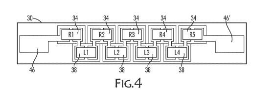
[0033] FIG. 4 is a plan view of an alternative, single-sided printed
circuit board
designed for enclosure by the in-line module of FIG. 1, showing an example of
the components used therein, according to an aspect of the disclosure;
[0034] FIG. 5 is an electronic schematic diagram of the filter module
according to
an aspect of the disclosure;
[0035] FIG. 6 is a graph of RF power delivered to a patient's skin for
three
different magnetic resonance radio frequencies when using a simulated in-line
filter module placed in one of various locations along a 240-millimeter cable
of an
electrode system, according to an aspect of the disclosure; and,
[0036] FIG. 7 is a graph of RF power delivered to a patient's skin at a
magnetic
resonance radio frequency of 128 MHz, such as used in 3-Tesla MRI machines,
placed along cables measuring 240, 300, 500, 700 and 1000 millimeters in
length, respectively.
DISCUSSION OF THE PRIOR ART
SUBSTITUTE SHEET (RULE 26)
CA 03126394 2021-07-09
WO 2020/150241 PCT/US2020/013514
[0037] An examination of the prior art in this field showed many U.S.
patents
already exist, including US 7,945,322; US 8,116,862; US8,180,448; US
8,200,328; US 8,301,243; US 8,311,628; US 8,463,375, US 8,649,857 and US
9,061,139) all by the same inventors (Stevenson et al.) and having the same
objective of creating implantable devices using tank circuits to block
specific
undesirable frequencies.
[0038] A tank circuit is the parallel combination of an inductor
(unavoidably
including some resistance) with a capacitor, which may be discrete such as a
manufactured chip or film capacitor or may include other capacitance
contributed
by nearby objects such as traces or copper areas left on a printed-circuit
board.
It blocks a typically narrow frequency range centered on fc = 1 I 2n (LC) ,
its
resonant center frequency, where fc is the frequency in hertz, L the
inductance in
henries, and C the capacitance in farads.
[0039] For example, an inductor with a value of 390 nanohenries ("L") and a
ten-
picofarad capacitor ("C") yield fc = 80.6 megahertz, close to the FM broadcast
band.
[0040] The effect of resistance in the tank is to change a parameter "0,"
which
becomes lower as the resistance increases. High "0" makes the tank a very
effective barrier at fc, with performance falling off sharply as the frequency
deviates from it. Low "0" broadens the frequency response, but at the expense
of performance close to fc.
[0041] Because it is difficult to control the values of inductors and
capacitors
precisely, and account for stray capacitance and the effect of magnetic
materials
in the environment around a tank circuit, some degree of individual adjustment
is
usually needed to make each tank resonate at the desired fc. This requires the
use of tunable components, such as adjustable capacitors, which are far more
costly than stock fixed-value ones. The tank must then be isolated from
outside
effects, which could affect its tuning. In production, this typically adds
significant
cost. As a further disadvantage, the tank will then block only that one
frequency
(and a narrow band of others near it) while having little or no effect at
others.
6
SUBSTITUTE SHEET (RULE 26)
CA 03126394 2021-07-09
WO 2020/150241 PCT/US2020/013514
[0042] The prime object of the invention, therefore, is to provide a
barrier against
RF energy in EEG electrode leads which avoids the disadvantages of tank
circuits by taking a wholly different approach: eliminating the use of
parallel
capacitance; treating the full electrode, cable and connector together as an
antenna-like system at all typically-used MRI radio frequencies; and in that
system placing in an optimal position along each cable a filter module
comprising
lumped inductance and resistance forming a non-resonant filter effective at
more
than one such frequency, the optimal position being that which causes a
minimum amount of RF energy to be delivered to the skin of a patient in
contact
with the electrode thereby minimizing the danger of burns.
[0043] Another object is to provide this RF energy barrier using
components able
to be used safely in an MRI environment, in the sense of being "MRI
conditional"
with field strengths and other conditions specified as needed.
[0044] A third object is to provide the MRI-compatible barrier using only
low-cost,
widely-available, stock-valued components requiring no individual adjustment
after assembly.
[0045] A fourth object is to provide the barrier in the form of a compact
filter
module which can be mounted in-line in the electrode cables and be safe for
use
in a medical environment.
[0046] A fifth object is to make such a module, and thereby the electrode
system
containing it, more tolerant of radio-frequency energy and robust against
resistance heating than the prior-art electrode systems.
DETAILED DESCRIPTION OF THE INVENTION
[0047] A computer model was developed for a set of neurological monitoring
electrodes to evaluate RF pickup from an RF device. The model was developed
using the commercially-available EZNEC+, Version 6.0 antenna modeling
software.
[0048] For this model, the electrodes, wires, connectors, and the
patient's head
are represented as parts of a radio-frequency receiving antenna. The patient's
head is divided into nineteen conductive volumes, each with its own resistance
7
SUBSTITUTE SHEET (RULE 26)
CA 03126394 2021-07-09
WO 2020/150241 PCT/US2020/013514
and capacitance, to simulate the distribution of radio-frequency current
through
an extended, electrically resistive load via the skin effect. The external
cables
are represented by straight wires, dangling wires, or a loop that includes a
capacitor representing a multi-electrode connector.
[0049] Loads, simulated by two 3000-ohm resistors, simulate the typical
resistance between the skin and each electrode. Additional loads, each
comprised of inductance and resistance, are modeled in a way permitting easy
relocation along the wires to simulate filter modules placed in varying
locations.
[0050] To simulate the rotating RF field around a patient undergoing MR
Imaging,
the "birdcage" coil used as an RF source in a typical MRI machine was modeled
as a set of four interconnected source dipoles, each dipole being 90 degrees
out
of phase with the next.
[0051] Referring now to FIGS. 1-5, Fig. 1 shows an electrode system 10
including
an electrode 14, a cable 18 with an in-line filter module 22, and a connector
26.
Cable 18 is in electrical connection with electrode 14 and with connector 26.
Electrode 14 may be attached to the head of a patient along with other
electrodes for neurological monitoring or other neurological procedure.
Connector 26 along with other connectors of other cables are connected to an
amplifier (not shown) to amplify the signals received from electrode 14 and
which
signals traveled through cable 18 and in-line filter module 22.
[0052] A cross-sectional view of in-line filter module 22, cut along line 2-
2 in
FIG.1, is shown in FIG. 2. In-line module 22 includes a housing 56 made from a
tough, electrically nonconductive and nontoxic polymer such as epoxy, silicone
rubber, polyvinyl chloride, polyethylene or polypropylene. Housing 56 contains
and protects a substrate 30, such as a small printed-circuit board, which is
shown
in perspective in FIG. 3, to which are attached plural resistors 34
alternatingly in
series with plural inductors 38. Substrate 30 is inserted in-line in cable 18
so
cable 18 is electrically connected to both ends of substrate 30 at contact pad
46,
46', with solder, conductive epoxy, graphite-paste "wire glue" or other
suitable
connecting material 50, 50'. Substrate 30, and thereby in-line filter module
22 is
thus in electrical connection with electrode 14 and connector 26.
8
SUBSTITUTE SHEET (RULE 26)
CA 03126394 2021-07-09
WO 2020/150241 PCT/US2020/013514
[0053] In FIGS. 3 and 4, resistors 34 and inductors 38 are shown as they
might
be mounted on two different types of printed circuit boards: double-sided in
FIG.
3 and single-sided in FIG. 4. In each case the number of inductors "N" is
four, so
the number of resistors "N+1" in an alternating set: resistor 34, inductor 38,
resistor 34, inductor 38, and so forth, with all resistors and inductors
connected
electrically in series. In FIG. 3, the inductors and resistors are placed on
opposite sides and connected through vias, while in FIG. 4 all components are
on the same side of the board. The latter approach simplifies construction,
though at the cost of an increase in overall width.
[0054] In any manufacturer's series of standard miniature surface-mount
inductors, those with higher inductance values have cores made of ferrite, a
magnetic ceramic, while lower-valued ones use nonmagnetic ceramics such as
porcelain or alumina. Typically, 390 nanohenries (0.39 microhenries) is the
largest value currently made without a ferrite core.
[0055] Although comprised chiefly of iron oxide, ferrites come in many
compositions optimized for different frequency ranges. They respond strongly
to
magnetic fields, both by experiencing physical force and by undergoing
magnetic
saturation which, if the ferrite is used in an inductor, will change the
inductor's
value. Accordingly, ferrite cores should be avoided in inductors meant for use
in
strong magnetic fields or near devices, such as MRI equipment, generating
them.
[0056] In simulation, values of inductance found usable for the invention
were in
the range of one to two microhenries with an optimal value around 1.56
microhenries (1560 nanohenries). This value is easily achieved by connecting
four ferrite-free, off-the-shelf 390-nanohenry miniature inductors
electrically in
series.
[0057] It is convenient for manufacturing, although otherwise not strictly
necessary, to make inductors 38 all have the same nominal value and
manufacturer's part number. For a total inductance of 1.56 microhenries,
divided
among four inductors as shown in FIGS. 3, 4 and 5, this nominal value, as just
stated, is 390 nanohenries.
9
SUBSTITUTE SHEET (RULE 26)
CA 03126394 2021-07-09
WO 2020/150241
PCT/US2020/013514
[0058] It should be stressed that nominal values include some error and are
typically given with tolerances of 1%, 5% or the like, so an inductor sold
as
"390 nanohenries 5%" might have an actual value lying anywhere from 370.5 to
[0059] 409.5 nanohenries. Differences of this order are often critical to
the
correct operation of tank circuits, but in the present design should make
little
difference.
[0060] The nominal values of each component type most often manufactured,
usually standardized among manufacturers, are known as stock values. 390
nanohenries is an example of such a stock value. It is possible that inductors
with different stock values than 390 nanohenries may in some cases be found
more convenient to use. For example, advances in miniature inductor
technology may yield higher inductance values without using ferrite, thus
permitting a needed value to be achieved using a smaller number of physically
discrete inductors.
[0061] Inductors 38 should be physically spaced a small distance apart so
their
magnetic fields do not overlap significantly. Such overlap, and the resulting
interaction between their fields, could change their effective total
inductance.
Spacing is conveniently achieved by setting them physically apart in an
alternating arrangement with the resistors, as shown in FIGS. 3 and 4.
Conveniently, the physically adjacent devices are then connected electrically,
again alternating between inductors and resistors, as shown schematically in
FIG. 5.
[0062] Such an alternating arrangement has the additional advantage of
distributing the heat from RF power dissipation in the resistors as widely as
possible along the length of the filter module, minimizing potential hot
spots. For
the latter reason, and since chip resistors are much less costly than
miniature
inductors, it is desirable- although not strictly necessary- to have one more
resistor ("N+1 ")than inductor ("N") as shown in FIGS. 3, 4 and 5, thus
distributing
any generated heat more widely.
[0063] Resistors may be selected to have a cumulative resistance of up to
1000
ohms, thus remaining within the input requirements for reliable operation of
most
SUBSTITUTE SHEET (RULE 26)
CA 03126394 2021-07-09
WO 2020/150241 PCT/US2020/013514
EEG amplifiers. To allow for resistance in the cable, connections and the
inductors themselves, however, it is desirable to make the actual total
resistance
within the filter module lower. Depending upon the values of those other
resistances, a total resistance as low as 1 ohm within the filter module may
be
found usable.
[0064] Just as with the inductors it is convenient for manufacturing,
although
otherwise not strictly necessary, to make resistors 34 all have the same
nominal
or stock value and manufacturer's part number.
[0065] For example, in a preferred embodiment a filter containing four
("N") 390-
nanohenry inductors built according to this invention would include five
("N+1")
resistors. Dividing 1000 ohms by five yields 200 ohms. The next few 1% stock
resistor values below 200 ohms are 196, 191, 187, 182 and 180 ohms. One of
these values, or possibly one still lower if other resistances in the system
are
expected to be high, should be selected and may then be optimized by a modest
amount of experiment.
[0066] A concrete example of in-line filter module 22 according to the
preferred
embodiment thus includes five resistors 34 each having a resistance of 180
ohms, and four ferrite-free inductors each having an inductance of 0.39
microhenries, arranged in alternation and connected in series beginning and
ending with a resistor 34. The complete module thus has a resistance of 900
ohms in series with 1.56 microhenries.
[0067] Simulation of the effectiveness of this in-line filter in a cable 18
between
an electrode 14 and a connector 26, and exposed to three different commonly-
used magnetic resonance frequencies, produced the response curves shown in
FIG. 6 as a functions of the location of in-line module 22, embodying the
concrete
example given, along a cable 18 that is 240 mm long. The horizontal axis
represents the distance along the wire from the electrode end, while the
vertical
axis shows the power delivered to a simulated skin resistance directly under
the
electrode. To avoid potential burns to the patient, as stated earlier, the
prime
object of the invention is to minimize this power.
11
SUBSTITUTE SHEET (RULE 26)
CA 03126394 2021-07-09
WO 2020/150241 PCT/US2020/013514
[0068] Curve 50, with calculated data points indicated by triangles, shows
the
delivered power at 64 MHz while for comparison horizontal dashed line 52 shows
a constant 8.8 milliwatts, the power with no filter module present. Given that
the
240-millimeter wire occupies only 5% of the 4.65-meter wavelength of the 64-
MHz RF energy, it functions very poorly as an antenna. Hence, the received and
delivered power levels are low and adding the filter module makes little
difference. RF burns have been of little concern with 1.5-Tesla MRI machines,
which use 64 MHz as the RF frequency.
[0069] Increasing the magnetic field strength in an MRI machine improves
the
image quality and resolution, and to maintain resonance, the RF frequency is
increased in proportion. Most new MRI machines operate at three Tesla,
requiring a frequency of 128 MHz with a corresponding wavelength of 2.33
meters. Here the 240-millimeter wire occupies about 10% of the 2.33-meter
wavelength, functioning much better as an antenna. This raises a definite
concern of injury to a patient from RF energy.
[0070] Curve 54 shows the delivered power, while again for comparison
dashed
line 56 shows the power with no filter module present. As is readily seen,
with no
filtering the power at 128 MHz, 43.8 milliwatts, is nearly five times what was
seen
at 64 MHz.
[0071] At 128 MHz a filter module according to the preferred embodiment now
has a strong effect on the delivered power, either raising or lowering it
depending
on the module's position. The region in which the module can be located to
reduce the delivered power is surprisingly broad compared to the wire's
length,
and the amount of reduction at the minimum point is very substantial. For
example, in a 240-millimeter wire, the minimum occurs with the module about
190 millimeters from the electrode, with delivered power of just 2.56
milliwatts:
only 6% of the value without the module present.
[0072] Experimental MRI machines now in development use still stronger
magnetic fields, typically of seven Tesla thus requiring an RF frequency of
299
MHz. Since at this frequency the 240-millimeter wire is nearly one-quarter
wavelength, it picks up RF energy very efficiently.
12
SUBSTITUTE SHEET (RULE 26)
CA 03126394 2021-07-09
WO 2020/150241 PCT/US2020/013514
[0073] Curve 58 shows a part of the resulting delivered power response,
which
extends far off the top of the chart at both ends. The power level without
filtering,
3.18 watts, cannot be shown for comparison without expanding the graph and
could easily be enough to cause serious injury to a patient. Installing the
preferred embodiment of the filter module 80 millimeters from the electrode
substantially reduces this power level to just 0.48 milliwatt: .015% of the
unfiltered value.
[0074] FIG. 7 shows the same curves for the three-Tesla frequency of 128
MHz
only, for varying lengths of wire measuring 240, 300, 500, 700 and 1000
millimeters in length, respectively. Wires 18a-18e are depicted to scale, with
electrodes 14a-14e at left and connectors 26a-26e at right.
[0075] Curve 54a reproduces curve 54 in FIG. 6 for the 240-millimeter wire
showing power dissipated at the patient's skin as a function of the location
of filter
module 22, while dashed curve 56a reproduces line 56 showing the power with
no filtering. Curves 54b, 54c, 54d and 54e, and dashed curves 56b, 56c, 56d
and 56e, show the corresponding power curves and unfiltered power levels in
the
300-, 500-, 700- and 1000-millimeter wires respectively.
[0076] As can be seen in FIG. 7, for each power curve a broad minimum
appears, containing within it a point 74a, 74b, 74c, 74d or 74e at which the
delivered power is minimized. For curves 74d and 74e, representing the
delivered power for the 700- and 1000-millimeter wires, a dashed line 74d' or
74e' has been added magnifying a portion of each curve to show the minimum
more clearly.
[0077] If filter modules 22a, 22b and so forth are drawn on each wire 18a,
18b
and so forth in their correct positions for minimizing the delivered power, it
can be
seen from FIG. 7 that they fall very nearly on a straight line 80. The slight
discrepancy may be due to the finite resolution ("segmentation") of the EZNEC
antenna modeling software.
[0078] For the concrete example described above, 900 ohms in series with
1.56
microhenries, used at a radio frequency of 128 megahertz, line 80 represents
an
optimum location for filter module 22 of LM = 0.27 L + 135,where L is the
total
13
SUBSTITUTE SHEET (RULE 26)
CA 03126394 2021-07-09
WO 2020/150241
PCT/US2020/013514
length of the electrode system 10, LM is the distance from electrode 14 to the
center of module 22, and all distances are expressed in millimeters. Similar
formulas can probably be derived for filter modules containing other values of
resistance and inductance.
[0079] It should be stressed, however, that since computer simulation
required
some simplifying assumptions the real-life measured curves will likely differ
slightly from those shown. Optimization may then be obtained by modest
experimentation that is well within the capability of those of ordinary skill
in the
art.
[0080] A series combination of inductors and resistors, without capacitors,
when
inserted into the cable of the electrode system in the form, for example, of
an in-
line filter module, forms an effective RF filter that reduces resistance
heating at
the patient's skin surface under and near the electrodes while being less
frequency-specific than a tank filter, able to be made with stock off-the-
shelf
components, and requiring no individual tuning after assembly.
[0081] Optimizing in-line filter module 22 through experimentation on the
number
and value of the components, which are resistors 34 and inductors 38, and no
capacitors; through favoring stock values for resistors 34 and inductors 38;
and
through favoring positions for in-line module 22 between the ends of cable 18,
and generally toward the middle of a 250 centimeter cable; may provide an MRI
cable 18 for electrode system 10 that has far fewer restrictions and is more
tolerant of radio-frequency energy and robust against resistance heating than
prior art electrode systems.
14
SUBSTITUTE SHEET (RULE 26)