Note: Descriptions are shown in the official language in which they were submitted.
CA 03126620 2021-07-13
WO 2020/207926 PCT/EP2020/059598
1
CHEMICAL SYNTHESIS PLANT
TECHNICAL FIELD
The present invention relates to a plant, such as a hydrocarbon plant, with
effective use of
various streams, in particular carbon dioxide. A method for producing a
product stream, such
as a hydrocarbon product stream is also provided. The plant and method of the
present
invention provide overall better utilization of carbon dioxide.
BACKGROUND
Carbon capture and utilization (CCU) has gained more relevance in the light of
the rise of
atmospheric CO2 since the Industrial Revolution. In one way of utilizing CO2,
CO2 and H2 can
be converted to synthesis gas (a gas rich in CO and Hz) which can be converted
further to
valuable products like alcohols (including methanol), fuels (such as gasoline,
jet fuel,
kerosene and/or diesel produced for example by the Fischer-Tropsch (F-T)
process), and/or
olefins etc.
Existing technologies focus primarily on stand-alone reverse Water Gas Shift
(rWGS)
processes to convert CO2 and H2 to synthesis gas. The synthesis gas can
subsequently be
converted to valuable products in the downstream processes as outlined above.
The reverse
water gas shift reaction proceeds according to the following reaction:
CO2 + H2 <¨> CO H20 (1)
The rWGS reaction (1) is an endothermic process which requires significant
energy input for
the desired conversion. Very high temperatures are needed to obtain sufficient
conversion of
carbon dioxide into carbon monoxide to make the process economically feasible.
Undesired
by-product formation of for example methane may also take place. High
conversions of
carbon dioxide can evidently also be obtained by high H2/CO2-ratio. However,
this will often
result in a synthesis gas with a (much) too high Hz/CO-ratio for the
downstream synthesis.
Technologies relying on the rWGS reaction have other challenges. In some
cases,
hydrocarbons may be available as co-feed. An example is the availability of
hydrocarbons
from a downstream synthesis stage (e.g. a propane and butane rich stream from
an F-T
stage; tail gas comprising different hydrocarbons from an F-T stage; naphtha
stream from an
CA 03126620 2021-07-13
WO 2020/207926 PCT/EP2020/059598
2
F-T stage; propane and butane rich stream from a gasoline synthesis stage; a
hydrocarbon
stream from olefin synthesis etc.). Such hydrocarbons cannot be processed in
an rWGS
reactor. If the hydrocarbon streams from the downstream synthesis stage are
not used at
least in part for additional production of synthesis gas, the overall process
may not be
feasible from an economic point of view. The same is the case if a hydrocarbon
stream, such
as natural gas, is available as co-feed to the plant.
To address problems with existing technologies, a novel process of syngas
preparation and
then, synthesis from the said syngas to syngas derived product(s) from
primarily CO2, H2 and
02 feed is presented in this document. The proposed layout has at least the
following
advantages:
1. CO2, Hz, and 02 can be converted to syngas with a desired Hz:CO ratio,
suitably
without using any hydrocarbon feed to the plant. If needed, one or more
hydrocarbon
co-feed to the plant can be used as well.
2. Utilization of any hydrocarbons generated in the synthesis stage for
synthesis gas
production
3. A higher utilization of the carbon dioxide feed is possible compared to a
stand-alone
rWGS section. One particular aim is to utilize more CO2 feed instead of
hydrocarbon
feed as a source of carbon.
4. Conversion of any hydrocarbon co-feed streams fed to the syngas stage is
possible.
5. If an electrolyzer is used as part or the entire source of the hydrogen
feed to the
process, part or all of the oxygen, generated in the electrolyzer along with
Hz, can be
used as the oxygen source that is required in the proposed process layout.
SUMMARY
In a first aspect, therefore, a method for producing a product stream is
provided. The method
comprises the steps of:
- providing a plant, said plant comprising:
a. a syngas stage, said syngas stage comprising an autothermal reforming (ATR)
section, and;
CA 03126620 2021-07-13
WO 2020/207926 PCT/EP2020/059598
3
b. a synthesis stage;
said plant comprising:
- a first feed comprising hydrogen to the syngas stage;
- a second feed comprising carbon dioxide to the syngas stage;
- a third feed comprising hydrocarbons to the syngas stage, upstream of said
ATR
section; and
- a fourth feed comprising oxygen to the ATR section;
wherein said syngas stage is arranged to provide a syngas stream and feed said
syngas
stream to the synthesis stage (B);
- supplying a first feed comprising hydrogen to the syngas stage;
- supplying a second feed comprising carbon dioxide to the syngas stage;
- supplying a third feed comprising hydrocarbons to the syngas stage,
upstream of said
ATR section;
- supplying a fourth feed comprising oxygen to the ATR section;
- providing a syngas stream in said syngas stage from at least said first,
second, third
and fourth feeds, and feeding said syngas stream to the synthesis stage;
- converting said syngas stream into at least a product stream and a
hydrocarbon-
containing off-gas stream in said synthesis stage;
wherein the ratio of moles of carbon in the third feed comprising
hydrocarbons, when
external to the plant, to the moles of carbon in CO2 in the second feed is
less than 0.5.
Various plants are provided for carrying out the method of the invention.
Further details of the plant and the method are specified in the following
detailed
descriptions, figures and claims.
CA 03126620 2021-07-13
WO 2020/207926 PCT/EP2020/059598
4
FIGURE LEGENDS
Figures 1-5 illustrate schematic layouts of various embodiments of a plant.
DETAILED DISCLOSURE
Unless otherwise specified, any given percentages for gas content are % by
volume.
Specific embodiments
As set out above, a plant ¨ such as - a hydrocarbon plant is provided. The
plant comprises:
a. a syngas stage, said syngas stage comprising an autothermal reformer (ATR)
section, and;
b. a synthesis stage;
The plant comprises various feeds. For the avoidance of doubt, the term "feed"
¨ when
applied to a plant ¨ refers to means for supplying said gas to the appropriate
stage, reactor
or unit; such as a duct, tubing etc.
A first feed comprising hydrogen is provided to the syngas stage. Suitably,
the first feed
consists essentially of hydrogen. The first feed of hydrogen is suitably
"hydrogen rich"
meaning that the major portion of this feed is hydrogen; i.e. over 75%, such
as over 85%,
preferably over 90%, more preferably over 95%, even more preferably over 99%
of this feed
is hydrogen. One source of the first feed of hydrogen can be one or more
electrolyser units.
In addition to hydrogen the first feed may for example comprise steam,
nitrogen, argon,
.. carbon monoxide, carbon dioxide, and/or hydrocarbons. The first feed
suitably comprises
only low amounts of hydrocarbon, such as for example less than 5% hydrocarbons
or less
than 3% hydrocarbons or less than 1% hydrocarbons.
A second feed comprising carbon dioxide is provided to the syngas stage.
Suitably, the
second feed consists essentially of CO2. The second feed of CO2 is suitably
"CO2 rich"
meaning that the major portion of this feed is CO2; i.e. over 75%, such as
over 85%,
preferably over 90%, more preferably over 95%, even more preferably over 99%
of this feed
is CO2. One source of the second feed of carbon dioxide can be one or more
exhaust
stream(s) from one or more chemical plant(s). One source of the second feed of
carbon
CA 03126620 2021-07-13
WO 2020/207926 PCT/EP2020/059598
dioxide can also be carbon dioxide captured from one or more process stream(s)
or
atmospheric air. Another source of the second feed could be CO2 captured or
recovered from
the flue gas for example from fired heaters, steam reformers, and/or power
plants. The
second feed may in addition to CO2 comprise for example steam, oxygen,
nitrogen,
5 oxygenates, amines, ammonia, carbon monoxide, and/or hydrocarbons. The
second feed
suitably comprises only low amounts of hydrocarbon, such as for example less
than 5%
hydrocarbons or less than 3% hydrocarbons or less than 1% hydrocarbons.
The first and second feeds could be mixed before being added to the syngas
stage.
The ratio of H2:CO2 provided at the plant inlet varies from 1.0-9.0,
preferably 2.5 ¨ 8, more
preferably 3.0 ¨ 7Ø The actual ratio will depend upon the desired end
product downstream
the synthesis stage. This ratio is defined as any H2 and CO2 in external
streams (i.e. not
including hydrogen and/or carbon dioxide in any recycle streams).
When the synthesis stage is an FT synthesis stage, the desired Hz/CO-ratio of
the synthesis
gas will typically be around 2. Using a simplistic view, one unit of hydrogen
is needed to
convert each unit of CO2 into CO. The addition of 02 will also require some
hydrogen and
furthermore hydrogen will be needed as source of energy for auxiliary purposes
such as for
example generation of power. All in all, this means that for an FT synthesis
stage the H2:CO2-
ratio at the plant inlet (i.e. not including hydrogen and/or carbon dioxide in
any recycle
streams) should be in the range of 3-7 or more preferably from 3-6 and most
preferably 3-5.
If the desired end product is methanol or gasoline (via synthesis of methanol
and the
methanol-to-gasoline route) a similar consideration can be made and also in
these cases the
H2:CO2-ratio at the plant inlet should be in the range of 3-7 or more
preferably from 3-6 and
most preferably 3-5.
It should be noted that in some cases H2:CO2 ratios less than 3 such as
between 2-3 can be
utilized. This could for example be the case if the third stream comprises
hydrogen or the
third stream is steam reformed to produce hydrogen. However, other scenarios
with an
H2:CO2 ratios lower than 3 are also conceivable.
A third feed comprising hydrocarbons is provided to the syngas stage, upstream
of the ATR
section. The third feed may additionally comprise other components such as CO2
and/or CO
and/or H2 and/or steam and/or other components such as nitrogen and/or argon.
Suitably,
the third feed consists essentially of hydrocarbons. The third feed of
hydrocarbons is suitably
"hydrocarbon rich" meaning that the major portion of this feed is
hydrocarbons; i.e. over
50%, e.g. over 75%, such as over 85%, preferably over 90%, more preferably
over 95%,
even more preferably over 99% of this feed is hydrocarbons. The concentration
of
CA 03126620 2021-07-13
WO 2020/207926 PCT/EP2020/059598
6
hydrocarbons in this third feed is determined prior to steam addition (i.e.
determined as "dry
concentration").
In one aspect, the third feed is fed to the syngas stage, directly upstream of
said ATR section
(i.e. without any intervening stage or unit). A "stage" comprises one or more
"units" which
perform a change in the chemical composition of a feed, and may additionally
comprise
elements such as e.g. heat exchanger, mixer or compressor, which do not change
the
chemical composition of a feed or stream.
An example of such third feed can also be a natural gas stream external to the
plant. In one
aspect, said third feed comprises one or more hydrocarbons selected from
methane, ethane,
propane or butanes.
The source of the third stream comprising hydrocarbons is external to the
plant. The
significance of a stream "external to the plant" is that the origin of the
stream is not a recycle
stream (or a recycle stream further processed or converted) from any synthesis
stage in the
plant. Possible sources of a third feed comprising hydrocarbons external to
the plant include
natural gas, LPG, refinery off-gas, naphtha, and renewables, but other options
are also
conceivable.
In some cases, a stream comprising hydrocarbons may be subjected to
prereforming before
being provided to the syngas stage as the third feed. For example, when the
third feed is e.g.
a LPG and/or a naphtha product stream or a natural gas feed, the plant may
further comprise
a pre-reforming section, arranged in the third feed, upstream the syngas
stage.
In a prereforming step, the following (endothermic) steam reforming reaction
and reaction
(3) (exothermic) take place to convert higher hydrocarbons. Additional water
gas shift and
methanation takes place through reactions (1) and (3):
CnHm + n H20 nC0 + (n + m/2)H2 (where r-1.2, m 4). (2)
CO2 + 4H2 CH4 + 2H20 (3)
The prereformer outlet stream will comprise CO2, CI-14, H20, and H2 along with
typically lower
quantities of CO and possible other components. The prereforming step
typically takes place
at 350-600 C or more preferably between 400 and 550 C. Steam is added to the
hydrocarbon
feed stream upstream the prereforming step. The prereforming step may take
place either
adiabatically or in a heated reactor, filled with catalysts including but not
limited to Ni-based
CA 03126620 2021-07-13
WO 2020/207926 PCT/EP2020/059598
7
catalysts. Heating of the prereformer can be achieved by means of hot gas
(e.g. ATR effluent
gas) or in a heating section for example using a fired heater. Hydrogen or
other combustible
components may be used to obtain the necessary heat input.
A hydrocarbon stream may also contain olefins. In this case the olefins may be
subjected to
hydrogenation to the corresponding paraffins before addition to a prereformer
or the syngas
stage as the third feed.
In some cases, the hydrocarbons contain minor amount of poisons, such as
sulfur. In this
case, the hydrocarbons may be subjected to the step or steps of purification
such as
desulfurization.
The third feed may comprise one or more streams comprising hydrocarbons that
are either
mixed or added separately to the syngas stage. The streams comprising
hydrocarbons may
either be recycled from the synthesis stage or be one or more separate streams
external to
the plant and not recycled from the synthesis stage.
A fourth feed comprising oxygen is provided to the ATR section. Suitably, the
fourth feed
consists essentially of oxygen. The fourth feed of 02 is suitably "02 rich"
meaning that the
major portion of this feed is 02; i.e. over 75% such as over 90% or over 95%,
such as over
99% of this feed is 02. This fourth feed may also comprise other components
such as
nitrogen, argon, CO2, and/or steam. This fourth feed will typically include a
minor amount of
steam (e.g. 5-10%). The source of fourth feed, oxygen, can be at least one air
separation
unit (ASU) and/or at least one membrane unit. The source of oxygen can also be
at least one
electrolyser unit. A part or all of the first feed, and a part or all of the
fourth feed may come
from at least one electrolyser. An electrolyser means a unit for converting
steam or water
into hydrogen and oxygen by use of electrical energy. Steam may be added to
the fourth
feed comprising oxygen, upstream the ATR section
In one aspect, the plant further comprises a steam feed (a fifth feed) to the
syngas stage.
Suitably, the ratio of moles of carbon in the third feed comprising
hydrocarbons, when
external to the plant, to the moles of carbon in CO2 in the second feed is
low; such as less
than 0.3, preferably less than 0.25 and more preferably less than 0.2 or even
lower than 0.1.
A value of this ratio less than 0.05 or 0.02 may also be considered. The lower
the value, the
lower the consumption of fossil fuels for a given production in the cases
where the external
hydrocarbon stream is a fossil fuel stream.
Syn gas Stage
CA 03126620 2021-07-13
WO 2020/207926 PCT/EP2020/059598
8
The syngas stage (A) is arranged to provide a syngas stream (from at least
said first to
fourth feeds) and feed said syngas stream to the synthesis stage (B). For the
avoidance of
doubt, the terms "syngas" and "synthesis gas" are synonymous. Furthermore, the
term
"provide a syngas stream" in this context must be understood as to "produce a
syngas
stream".
The syngas stage comprises an autothermal reformer (ATR) section. The syngas
stage may
comprise additional sections as required. Various sections will be described
in the following.
ATR Section
In one aspect, the syngas stage consists of said autothermal reforming (ATR)
section,
comprising one or more autothermal reactors (ATR), and wherein first, second,
third, and
fourth feeds are fed to said ATR section. Part or all of the third feed may be
desulfurized and
prereformed. All feeds are preheated as required. The key part of the ATR
section is the ATR
reactor. The ATR reactor typically comprises a burner, a combustion chamber,
and a catalyst
bed contained within a refractory lined pressure shell. In an ATR reactor,
partial combustion
of the hydrocarbon containing feed by sub-stoichiometric amounts of oxygen is
followed by
steam reforming of the partially combusted hydrocarbon feed stream in a fixed
bed of steam
reforming catalyst. Steam reforming also takes place to some extent in the
combustion
chamber due to the high temperature. The steam reforming reaction is
accompanied by the
water gas shift reaction. Typically, the gas is at or close to equilibrium at
the outlet of the
reactor with respect to steam reforming and water gas shift reactions. More
details of ATR
and a full description can be found in the art such as "Studies in Surface
Science and
Catalysis, Vol. 152," Synthesis gas production for FT synthesis"; Chapter 4,
p.258-352,
2004".
Typically, the effluent gas from the ATR reactor has a temperature of 900-1100
C. The
effluent gas normally comprises Hz, CO, CO2, and steam. Other components such
as
methane, nitrogen, and argon may also be present often in minor amounts. The
operating
pressure of the ATR reactor will be between 5 and 100 bars or more preferably
between 15
and 60 bars.
The syngas stream from the ATR is cooled in a cooling train normally
comprising a waste
heat boiler(s) (WHB) and one or more additional heat exchangers. The cooling
medium in the
WHB is (boiler feed) water which is evaporated to steam. The syngas stream is
further cooled
to below the dew point for example by preheating the utilities and/or partial
preheating of
one or more feed streams and cooling in air cooler and/or water cooler.
Condensed H20 is
CA 03126620 2021-07-13
WO 2020/207926 PCT/EP2020/059598
9
taken out as process condensate in a separator to provide a syngas stream with
low H20
content, which is sent to the synthesis stage.
The "ATR section" may be a partial oxidation "PDX" section. A PDX section is
similar to an
ATR section except for the fact that the ATR reactor is replaced by a PDX
reactor. The PDX
rector generally comprises a burner and a combustion chamber contained in a
refractory
lined pressure shell.
The ATR section could also be a catalytic partial oxidation (cP0X) section.
Methanation Section
In one aspect, the syngas stage additionally comprises a methanation section
arranged
upstream the ATR section. The methanation section is in fluid connection with
said ATR
section. A part or all of the first feed is fed to the methanation section; a
part or all of the
second feed is fed to the methanation section; and a part or all of the third
feed is fed to the
syngas stage, upstream said methanation section and/or between said
methanation section
and said ATR section.
The heat generated in the methanation process obviates completely or reduces
significantly
the need for external preheating of the feed to the autothermal reforming
section. Such
external preheating may for example take place in a fired heater. The required
heat in such a
fired heater is generated by combustion of for example hydrogen and/or a
hydrocarbon. In
the former case this consumes part of the feed and in the second case this
leads to CO2
emissions. Furthermore, a fired heater is an expensive piece of equipment
which may also
take up a considerable plot area. Finally, the methanation section upfront the
ATR section
improves the overall plant efficiency for example compared to a stand-alone
ATR section.
As indicated earlier, state of art for producing a synthesis gas from CO2 and
hydrogen is
based on selective RWGS. Compared to this scheme, the combination of
methanation and
.. ATR has several advantages. This includes the possibility of utilizing a
hydrocarbon containing
stream both external to the plant and internal recycle streams. Furthermore,
the outlet
temperature from the ATR reactor in the ATR section will typically be in the
range of 900-
1100 C. This is in most cases higher than is possible with a stand-alone RWGS
unit. This
increases the production of carbon monoxide as tis is thermodynamically
favoured by higher
temperature. It should also be noted that even if methane is formed in the
methanation
section, the content of methane in the final synthesis gas sent to the
synthesis stage is low
due to the high exit temperature from the ATR reaction in the ATR section.
Advantageously,
the exit temperature from the ATR is between 1000-1100 C.
CA 03126620 2021-07-13
WO 2020/207926 PCT/EP2020/059598
It is an advantage for most applications that the content of methane in the
synthesis gas
sent to the synthesis stage is low. For most types of synthesis stages,
methane is an inert or
even a synthesis stage byproduct. Hence, in one preferred embodiment, the
content of
methane in the synthesis gas sent to the synthesis stage is less than 5%, such
as less than
5 3% or even less than 2%.
It seems counterintuitive to insert a methanation section upstream an ATR
section. In the
methanation section methane is formed and a large part of the formed methane
is then
converted in the ATR section. However, the applicants have found that the heat
of
methanation can be utilized for preheating the feed to the ATR section. This
avoids or
10 reduces the need for a dedicated feed preheater. Reducing the preheat
duty will also reduce
the required combustion to provide the required energy and thereby the
emissions of CO2 in
case the preheater is a fired heater with hydrocarbon fuel. The methanation
section may
comprise one or more methanation units, arranged in series, such as two or
more
methanation units, three or more methanation units, four or more methanation
units. In such
methanation units, CO2 and H2 are primarily converted to methane and steam via
an
exothermic methanation reaction. Each of the methanation units may be either
adiabatic or
cooled by means for example of boiling water or by heating for example the
feed gas. The
effluent temperature from each methanation unit can be 250 - 900 C, preferably
600 ¨
850 C, more preferably 650 ¨ 840 C, depending on the extent of methanation and
extent of
cooling. Parallel methanation units are also conceivable.
Parts of the first feed comprising hydrogen may be fed separately to different
methanation
units in the methanation section; or the entire first feed comprising hydrogen
may be fed
together to the methanation unit located furthest upstream in the methanation
section.
Similarly, parts of the second feed comprising carbon dioxide may be fed
separately to
different methanation units in the methanation section; or the entire second
feed comprising
carbon dioxide may be fed together to the methanation unit located furthest
upstream in the
methanation section. Furthermore, parts of the third feed comprising
hydrocarbons may be
fed separately to different methanation units in the methanation section; or
the entire third
feed comprising hydrocarbons may be fed together to one methanation unit in
the
methanation section.
In a specific embodiment, all of the first feed comprising hydrogen is fed to
the first of the
methanation units together with part of the second feed comprising carbon
dioxide. The
remaining part of the carbon dioxide is distributed between the remaining
methanation units
and the exit temperature of the final methanation unit is between 650-900 C
such as
between 750-850 C.
CA 03126620 2021-07-13
WO 2020/207926 PCT/EP2020/059598
11
Additional H2 feed and/or CO2 feed can be added to different parts of the
methanation
section. For instance, part of the hydrogen or CO2 feed could be provided to a
second (or
even third...) methanation unit. Additionally, part of the effluent from one
methanation unit
can be cooled and recycled to the inlet of said methanation unit and/or to the
inlet of any
additional methanation unit(s) located upstream said one methanation unit.
Optionally,
effluent from methanation section can be cooled below its dew point and a part
of the water
may be removed from this effluent before it is recycled to the inlet of the
methanation unit or
any upstream methanation unit.
Addition of steam to the methanation section and/or between the methanation
section and
the ATR section may also occur.
In this aspect, the exothermic nature of the methanation reaction may be
utilized for
preheating the ATR feed. Some heating of the ATR section by external means may
be either
needed or desirable for example for control purposes. Therefore, the reaction
heat of the
methanation reaction may only cause part of the temperature increase upstream
the ATR
section.
The methanation reaction can be expressed by:
CO2+4H2 CH 4 + 2H20 (3)
Normally, the rWGS (reaction (1) and/or the water gas shift reaction (reverse
of reaction (1))
will also take place in the methanation unit. In many cases, the gas
composition at the exit of
each methanation unit will be at or close to chemical equilibrium with respect
to the water
gas shift/reverse water gas shift and the methanation reactions at the exit
temperature and
pressure of said methanation unit.
The methanation reaction (3) is very exothermic. In some cases, it is
desirable to adjust the
temperature at the outlet of a methanation unit or from the methanation
section to a given
value, which may be in the range of 250-900 C such as between 600-850 C. If
part or all of
the third feed comprising hydrocarbons is added to a methanation unit, this
will reduce the
exit temperature due to the fact that steam reforming (reverse of reaction (3)
and/or
reaction (2)) will take place.
If instead, the effluent from the prereforming step is added to a methanation
unit, the same
effect will be obtained. The methane in the prereforming effluent will react
according to the
endothermic steam reforming reaction:
CA 03126620 2021-07-13
WO 2020/207926 PCT/EP2020/059598
12
CH4 + H20 4- CO + 3H2 (4)
The presence of methane in the feed will limit the extent of the methanation
reaction due to
the chemical equilibrium. The output from the methanation section is a stream
comprising
CO2, Hz, CO, H20 and CH4.
A tail gas from an FT synthesis stage will normally not be added to a
methanation unit but
fed directly to the ATR section. If excess tail gas from the FT synthesis
stage is available, this
may be hydrogenated and fed to the methanation section.
In some cases, it may be desirable to avoid to too high temperatures in the
methanation unit
for example to limit the extent of deactivation of the catalyst due to
sintering. This is
especially the case if the methanation unit or methanation reactor is
adiabatic. The highest
temperature in an adiabatic methanation unit will normally be at the outlet.
Hence, it may be
desirable to control the exit temperature from one or more methanation units
to for example
a temperature in the range 600-750 C, such as about 650 C, 675 C, 700 C, or
725 C. This
may be accomplished by controlling the feed streams to the individual
methanation units in
the methanation section, if more than one methanation unit is present. By
controlling the
molar ratios between the part of the first feed and the part of the second
feed as well as the
molar ratio between the part of the first feed and the part of the fifth feed
(if present) added
to a methanation unit, it is possible to control the exit temperature of an
adiabatic
methanation unit. Obviously, the inlet temperature(s) of the feed streams can
also be used
for this purpose.
In one embodiment, the inlet temperature of at least one of the methanation
units will be
between 300-500 C.
The control of the ratios of the various feed streams to each of the
methanation units and the
ratios of the various feed streams fed to the methanation section and directly
to the ATR
section may also be used to impact the synthesis gas composition.
The extent of methanation (and thereby the composition of the gas to the ATR
section)
depends on a number of factors including the ratio of the feed streams to the
methanation
section and the inlet and exit temperature to and from each methanation unit
and the extent
of water removal (if any) from the methanation section. For a given gas
composition and
temperature of the gas to the ATR section, the synthesis gas from the ATR
depends upon the
amount of oxygen added. Increasing the amount of oxygen increases the ATR
reactor exit
temperature and thereby reduces the H2/CO-ratio.
CA 03126620 2021-07-13
WO 2020/207926 PCT/EP2020/059598
13
In another embodiment (illustrated in Figure 4c) the syngas stage (A)
comprises a
methanation section (II) arranged in parallel to said ATR section (I). At
least a portion of the
first feed and at least a portion of the second feed are arranged to be fed to
the methanation
section (II) and said methanation section (II) is arranged to convert said at
least a portion of
the first feed and at least a portion of the second feed to a first syngas
stream. A third feed
comprising hydrocarbons and a fourth feed comprising oxygen are arranged to be
fed to the
ATR section (I); and wherein said ATR section (I) is arranged to convert said
third feed
comprising hydrocarbons and said fourth feed comprising oxygen ¨ along with
the remaining
portions of the first and second streams ¨ to a second syngas stream. The
first syngas
stream from the methanation section (II) is arranged to be combined with the
second syngas
stream from the ATR section (I); and the combined syngas stream is arranged to
be fed to
the synthesis stage (B).
Compared to in series methanation and ATR section, this embodiment reduces the
amount of
oxygen needed.
Reverse Water Gas Shift (rWGS) Section
In a further aspect, the syngas stage comprises a reverse water gas shift
(rWGS) section
upstream the ATR section. The reverse water gas shift (rWGS) section is in
fluid connection
with said ATR section. A part or all of the first feed is fed to the rWGS
section; a part or all of
the second feed is fed to the rWGS section; and wherein a part or preferably
all of the third
feed may be fed to the syngas stage between said rWGS section (III) and said
ATR section.
As indicated earlier, state of art for producing a synthesis gas from CO2 and
hydrogen is
based on selective RWGS. Compared to this scheme, the combination of RWGS and
ATR has
several advantages. This includes the possibility of utilizing a hydrocarbon
containing stream
both external to the plant and internal recycle streams. Such streams can be
added to the
ATR section and utilized for additional synthesis gas production compared to
what is possible
with a stand-alone and selective RWGS. Furthermore, the outlet temperature
from the ATR
reactor in the ATR section will typically be in the range of 900-1100 C. This
is in most cases
higher than is possible with a stand-alone RWGS unit. This increases the
production of carbon
monoxide as this is thermodynamically favoured by higher temperature.
In one aspect, the rWGS section comprises one or more rWHS units, arranged in
series e.g.
two or more rWGS units, such as three or more rWGS units. In such rWGS units,
CO2 and H2
are converted to CO and H2 via reaction (1) above. Parallel reverse water gas
shift units are
also conceivable.
CA 03126620 2021-07-13
WO 2020/207926 PCT/EP2020/059598
14
Parts of the first feed comprising hydrogen may be fed separately to different
rWGS units in
the rWGS section; or the entire first feed comprising hydrogen is fed together
to the reverse
WGS unit located furthest upstream in the rWGS section. Similarly, parts of
the second feed
comprising carbon dioxide may be fed separately to different rWGS units in the
rWGS
section; or the entire second feed comprising carbon dioxide is fed all
together to the rWGS
unit located furthest upstream in the rWGS section.
Each of the rWGS units may be either adiabatic or a heated reactor. Heating
can be achieved
by means of hot effluent from ATR or utilizing heat of combustion of, for
example - a stream
comprising hydrocarbons and/or a stream comprising hydrogen. The effluent from
the rWGS
.. section is a stream comprising CO2, Hz, CO, H20. The rWGS effluent
temperature from each
rWGS unit can be 400 - 900 C, preferably 500 ¨ 900 C, more preferably 500 ¨
750 C,
depending on the extent of rWGS and extent of heating.
The effluent from the rWGS section is fed to the ATR section. A methanation
section, in one
specific embodiment, may be placed between the rWGS section and the ATR
section. In this
case the effluent from the rWGS section is fed to the methanation section and
the effluent
from the methanation section is fed to the ATR.
Reverse Water Gas Shift (rWGS) Section ¨ alternative arrangement
In a further aspect, the syngas stage comprises a reverse water gas shift
(rWGS) section
which is arranged in parallel to said ATR section. The reverse water gas shift
(rWGS) section
is in fluid connection with said ATR section. A part or all of the first feed
is fed to the rWGS
section; a part or all of the second feed is fed to the rWGS section; wherein
the said rWGS
section is arranged to convert at least a portion of the first feed and at
least a portion of the
second feed to a syngas stream comprising Hz, CO, CO2 and H20.
Third feed comprising hydrocarbons and a fourth feed comprising oxygen along
with
.. optionally a portion of first feed comprising hydrogen and/or optionally a
portion of second
feed comprising carbon dioxide are arranged to feed to the ATR section;
wherein the ATR
section is arranged to convert the feed streams to another syngas stream
comprising Hz, CO,
CO2, CH4and H20.
In this aspect, syngas streams from the rWGS section and the ATR section are
arranged to be
combined to obtain a final syngas stream; wherein the said final syngas stream
is fed to
synthesis stage.
CA 03126620 2021-07-13
WO 2020/207926 PCT/EP2020/059598
As indicated earlier, state of art for producing a synthesis gas from CO2 and
hydrogen is
based on selective RWGS. Compared to this scheme, the combination of a
parallel RWGS and
ATR has several advantages. This includes the possibility of utilizing a
hydrocarbon containing
stream both external to the plant and internal recycle streams. Converting
part of the CO2 in
5 the RWGS section has the advantage that the overall oxygen consumption
may be reduced.
As above, this rWGS section may comprise one or more rWHS units, arranged in
series e.g.
two or more rWGS units, such as three or more rWGS units. In such rWGS units,
CO2 and H2
are converted to CO and H2 via reaction (1) above. Parallel reverse water gas
shift units are
also conceivable.
10 Parts of the first feed comprising hydrogen may be fed separately to
different rWGS units in
the rWGS section; or the entire first feed comprising hydrogen is fed together
to the reverse
WGS unit located furthest upstream in the rWGS section. Similarly, parts of
the second feed
comprising carbon dioxide may be fed separately to different rWGS units in the
rWGS
section; or the entire second feed comprising carbon dioxide is fed all
together to the rWGS
15 unit located furthest upstream in the rWGS section.
Each of the rWGS units may be either adiabatic or a heated reactor. Heating
can be achieved
by means of hot effluent from ATR or utilizing heat of combustion of, for
example - a stream
comprising hydrocarbons and/or a stream comprising hydrogen. The effluent from
the rWGS
section is a stream comprising CO2, Hz, CO, H20. The rWGS effluent temperature
from each
rWGS unit can be 400 - 900 C, preferably 500 ¨ 900 C, more preferably 500 ¨
750 C,
depending on the extent of rWGS and extent of heating.
Post ATR CO2-conversion unit
In another aspect, the plant comprises a post-conversion (post-ATR conversion,
PAC) unit or
reactor, located downstream the ATR section.
The PAC unit may be either adiabatic or a heated reactor using for example a
Ni-based
catalyst and/or a catalyst with noble metals such as Ru, Rh, Pd, and/or Ir as
the active
material. In such a PAC unit, a stream comprising carbon dioxide such as part
of the second
feed and part or all of the syngas from the ATR section is mixed and directed
to the PAC unit.
The mixed stream is converted to a syngas with higher carbon monoxide content
via both
reactions (3) and (1) ¨ above ¨ in the PAC unit. Reactions (3) and (1) will
typically be at or
close to chemical equilibrium at the outlet of the PAC unit. The effluent from
the PAC section
is a stream comprising CO2, Hz, CO, H20 and CHa. The PAC effluent temperature
from each
PAC unit can be 700 - 1000 C, preferably 800 ¨ 950 C, more preferably 850 ¨
920 C. The
CA 03126620 2021-07-13
WO 2020/207926 PCT/EP2020/059598
16
advantage of the PAC unit is the ability to produce a synthesis gas a lower
Hz/CO-ratio
compared to the effluent stream from the ATR section. Furthermore, the fact
that a stream
comprising carbon dioxide such as part of the second feed is directed to the
PAC unit (such
as an adiabatic PAC unit) instead of to the ATR section, reduces the size of
the ATR section.
This may in some cases reduce the overall cost.
The effluent stream from the PAC unit is cooled as described above to provide
a syngas
stream for the synthesis stage.
This CO2-conversion (PAC) unit may be included in any of the aspects described
above.
Synthesis Stage
The synthesis stage is typically arranged to convert the syngas stream into at
least a product
stream.
Often a hydrocarbon-containing off-gas stream is generated in the synthesis
stage. Suitably,
at least a portion of said hydrocarbon-containing off-gas stream is fed to the
syngas stage in
addition to said third feed comprising hydrocarbons.
A few examples (not exhaustive) of possible off-gas streams to be fed to the
syngas stage in
addition to the third feed comprising hydrocarbons; and corresponding
synthesis stages are
provided in the following table.
Synthesis stage technology Possible off-gas streams from synthesis stage
Fischer-Tropsch (F-T) Tail gas
Propane / butane rich stream (LPG)
Naphtha rich stream
Methanol (Me0H) synthesis Purge gas
Me0H to gasoline (MTG) Purge gas
Propane / butane rich stream (LPG)
CA 03126620 2021-07-13
WO 2020/207926 PCT/EP2020/059598
17
Higher alcohol synthesis (HA) Tail gas
Methane rich stream
Syngas-to-Olefin (STO) synthesis CO2-rich off gas
Hydrocarbon rich stream
In the case where off-gas stream is fed to the syngas stage in addition to the
third feed
comprising hydrocarbons, the requirement for an external hydrocarbon feed may
be reduced.
The syngas stream at the inlet of said synthesis stage suitably has a Hz:CO
ratio in the range
1.00 ¨ 4.00; preferably 1.50 ¨ 3.00, more preferably 1.50 ¨ 2.10. If the
synthesis stage is an
FT stage, the Hz:CO ratio is preferably in the range 1.50-2.10.
In another embodiment, the syngas stream at the inlet of said synthesis stage
suitably has a
(Hz - CO2)/(CO + CO2) ratio in the range 1.50 ¨ 2.50; preferably 1.80 ¨ 2.30,
more
preferably 1.90 ¨ 2.20. This stoichiometry is suitable for methanol synthesis.
The present technology and the composition of syngas can be applied to a
variety of
syntheses and synthesis stages. A few potential examples of the synthesis
stage are provided
in the following.
Fischer-Tropsch Synthesis stage
In one aspect, the synthesis stage is a Fischer-Tropsch synthesis (F-T) stage.
The F-T stage
comprises Fischer-Tropsch (F-T) synthesis section where syngas from syngas
stage is first
converted to at least a raw product comprising hydrocarbons and a hydrocarbon
containing
off-gas stream in form of an F-T tail gas stream followed by hydroprocessing
and
hydrocracking section where said raw product is converted to at least one or
more
hydrocarbon product streams. The composition of the raw product from the F-T
synthesis
section depends on the type of catalyst, reaction temperature etc. that are
used in the
process.
A hydrocarbon-containing off-gas stream in the form of an F-T tail gas stream
is produced as
side-product. The F-T tail gas stream typically comprises carbon monoxide (10-
40 vol. %),
CA 03126620 2021-07-13
WO 2020/207926 PCT/EP2020/059598
18
hydrogen (10-40 vol %), carbon dioxide (10-50 vol %), and methane (10-40 vol
Ai).
Additional components such as argon, nitrogen, olefins, and paraffins with two
or more
carbon atoms may also be present in smaller amounts.
At least a portion of said F-T tail gas stream may be fed to the syngas stage
in addition to
said third feed comprising hydrocarbons. Suitably, to avoid excessive build-up
of inert
components, that may be present in F-T tail gas, only a portion of said F-T
tail gas stream is
fed to the syngas stage; and another portion of the F-T tail gas may be purged
and/or used
as fuel and/or converted to power. In one embodiment said power can be used as
(partial)
source for an electrolysis unit if present. Alternatively, the power can be
exported.
In one embodiment, the major product from F-T synthesis stage is/are typically
jet fuel
and/or kerosene (e.g. comprising primarily C12 ¨ C15) and/or diesel (e.g.
comprising primarily
C15 ¨ C20)= Besides, naphtha (e.g. comprising primarily C5 ¨ C12) and LPG
(e.g. comprising
primarily C3 ¨ C4) streams are also produced in F-T synthesis stage. A part or
all of such LPG
and/or naphtha stream(s) from F-T synthesis stage may also be used additional
to the third
feed comprising hydrocarbons to syngas stage. A part or all of such LPG and/or
naphtha
stream(s) may be added to the methanation section and/or directly to the ATR
section. In
another embodiment, a part or all of such LPG and/or naphtha may be subjected
to
prereforming section before addition to the methanation section and/or the ATR
section.
In one particular embodiment, therefore, the synthesis stage is a Fischer-
Tropsch synthesis
(F-T) stage arranged to convert said syngas stream from said syngas stage into
at least a
hydrocarbon product stream, being a diesel stream; and an LPG and/or a naphtha
product
stream and/or kerosene or jet fuel product stream, and wherein at least a
portion of said LPG
and/or a naphtha product stream is fed to the syngas stage in addition to said
third feed
comprising hydrocarbons. In one aspect, at least a portion of the FT tail gas,
at least a
portion of the LPG and at least a portion of the naphtha product stream are
fed to the syngas
stage. In another aspect, at least a portion of the FT tail gas and at least a
portion of the LPG
are fed to the syngas stage. The LPG and/or naphtha stream(s) may be treated
by
prereforming before being fed to the syngas stage.
Methanol synthesis stage
In another embodiment, the synthesis stage is a methanol (Me0H) synthesis
stage. This
stage comprises a Me0H synthesis section where syngas from the syngas stage is
first
converted to a raw Me0H stream, followed by a purification section where said
raw Me0H
stream is purified to obtain a Me0H product stream. The Me0H synthesis stage
generates a
purge gas stream, which typically contains hydrogen, carbon dioxide, carbon
monoxide and
CA 03126620 2021-07-13
WO 2020/207926 PCT/EP2020/059598
19
methane. Additional components such as argon, nitrogen, or oxygenates with two
or more
carbon atoms may also be present in smaller amounts.
At least a portion of said Me0H purge gas stream may be fed to the syngas
stage in addition
to said third feed comprising hydrocarbons. The Me0H purge gas stream may be
purified
prior to feeding it to the syngas stage. Suitably, to avoid excessive build-up
of inert
components that may be present in the Me0H purge gas, only a portion of said
Me0H purge
gas stream may be fed to the syngas stage; and another portion of the Me0H
purge gas may
be purged and/or used as fuel.
In particular when the synthesis stage is a methanol synthesis stage, the
syngas stream at
the outlet of said syngas stage has a module, as defined herein, in the range
1.80 ¨ 2.30;
preferably 1.90 ¨ 2.20. The term "module" is defined as:
(H2 co2)
Module, M ¨ _______________________________________
(CO + CO2)
Methanol-to-gasoline (MTG) synthesis stage
In another embodiment, the synthesis stage is a Me0H-to-gasoline (MTG)
synthesis stage
comprising a Me0H synthesis section where syngas from syngas stage is first
converted to
raw Me0H stream followed by a gasoline synthesis section where said raw Me0H
stream is
converted to gasoline product stream.
The MTG synthesis stage also generates a purge gas stream. This purge gas
stream can be
utilized similarly as explained in the previous section under 'Methanol
synthesis stage'.
The MTG synthesis stage generates LPG (e.g. comprising primarily C3 ¨ C4)
stream. A part or
all of such LPG stream from MTG synthesis stage may also be fed additional to
the said third
feed comprising hydrocarbons to the syngas stage. A part or this entire LPG
stream may be
added to the methanation section and/or directly to the ATR section. In
another embodiment,
a part or all of said LPG stream may be subjected to prereforming before
addition to the
metha nation section and/or the ATR section.
Higher alcohol (HA) synthesis
CA 03126620 2021-07-13
WO 2020/207926 PCT/EP2020/059598
In another embodiment, the synthesis stage is a higher alcohol (HA) synthesis
stage
comprising HA synthesis section where syngas from syngas stage is first
converted to raw
alcohol stream followed by purification section where said raw alcohol stream
is purified to
get HA product stream.
5 HA synthesis stage may generate a tail gas stream, which typically
contains hydrogen,
carbon dioxide, carbon monoxide. Additional components such as argon,
nitrogen, methane,
oxygenates with two or more carbon atoms may also be present in smaller
amounts.
HA synthesis stage may also generate a methane rich stream, which typically
contains
methane, hydrogen and carbon monoxide. Additional components such as argon,
nitrogen,
10 carbon dioxide, oxygenates with two or more carbon atoms may also be
present in smaller
amounts.
At least a portion of said tail gas and/or said methane rich stream(s) may be
fed to the
syngas stage in addition to said third feed comprising hydrocarbons. Suitably,
to avoid
excessive build-up of inert components, that may present in said tail gas
and/or said
15 methane rich stream(s), only a portion of said tail gas and/or said
methane rich stream(s)
may be fed to the syngas stage; and the another portion may be purged and/or
used as fuel.
Syngas-to-Olefins (STO) synthesis
In another embodiment, the synthesis stage is a syngas-to-olefins (STO)
synthesis stage
comprising STO synthesis section where syngas from syngas stage is first
converted to raw
20 olefin rich stream followed by purification section where said raw
olefin rich stream is purified
to get olefin product stream.
STO synthesis stage may generate a tail gas stream, which typically contains
hydrogen,
carbon dioxide, carbon monoxide. Additional components such as argon,
nitrogen, methane,
hydrocarbons with two or more carbon atoms may also be present in smaller
amounts.
STO synthesis stage may also generate a hydrocarbon rich stream, which
typically contains
methane and higher hydrocarbons with two or more carbon atoms. Higher
hydrocarbons may
be both olefins and paraffins. Additional components such as hydrogen, carbon
dioxide,
carbon monoxide, argon, nitrogen may also be present in smaller amounts.
At least a portion of said tail gas and/or said hydrocarbon rich stream(s) may
be fed to the
syngas stage in addition to said third feed comprising hydrocarbons. Suitably,
to avoid
excessive build-up of inert components, that may present in said tail gas
and/or said
CA 03126620 2021-07-13
WO 2020/207926 PCT/EP2020/059598
21
hydrocarbon rich stream(s), only a portion of said tail gas and/or said
hydrocarbon rich
stream(s) may be fed to the syngas stage; and the another portion may be
purged and/or
used as fuel.
Syngas-to-ethylene oxide (STEt0) synthesis
In another embodiment, the synthesis stage is a syngas-to-ethylene oxide
(STEt0) synthesis
stage. The STEt0 stage comprises syngas-to-olefin (STO) synthesis section,
where syngas is
first converted to olefin product (mainly ethylene), followed by the ethylene
oxide synthesis
section.
STO synthesis stage may generate a tail gas stream, which typically contains
hydrogen,
carbon dioxide, carbon monoxide. Additional components such as argon,
nitrogen, methane,
hydrocarbons with two or more carbon atoms may also be present in smaller
amounts.
STO synthesis stage may also generate a hydrocarbon rich stream, which
typically contains
methane and higher hydrocarbons with two or more carbon atoms. Higher
hydrocarbons may
be both olefins and paraffins. Additional components such as hydrogen, carbon
dioxide,
.. carbon monoxide, argon, nitrogen may also be present in smaller amounts.
At least a portion of said tail gas and/or said hydrocarbon rich stream(s) may
be fed to the
syngas stage in addition to said third feed comprising hydrocarbons. Suitably,
to avoid
excessive build-up of inert components, that may present in said tail gas
and/or said
hydrocarbon rich stream(s), only a portion of said tail gas and/or said
hydrocarbon rich
stream(s) may be fed to the syngas stage; and the another portion may be
purged and/or
used as fuel.
The ethylene oxide synthesis section may use at least a part of the fourth
feed (02). Lots of
CO2 is generated as by-product during ethylene oxide synthesis. The CO2 by-
product can be
recycled and used at least a part of the first feed to syngas stage.
Combined gasoline and diesel production
In another embodiment, synthesis stage can be combination of F-T section and
methanol-to-
gasoline (MTG) synthesis sections in parallel with common syngas feed from
syngas stage.
The F-T section produces middle distillate products (diesel/jet fuel/kerosene
etc.), and MTG
produces gasoline with desired octane number. In this embodiment, syngas stage
provides
syngas of suitable quality to both F-T and MTG sections, operating in parallel
to each other.
At least a part of recycle gas from F-T and/or at least a part of LPG stream
from MTG section
CA 03126620 2021-07-13
WO 2020/207926 PCT/EP2020/059598
22
and/or at least a part of purge stream from Me0H synthesis section can be used
as third feed
to syngas stage.
Electrolyzer
The plant may further comprise an electrolyser arranged to convert water or
steam into at
least a hydrogen-containing stream and an oxygen-containing stream, wherein at
least a part
of said hydrogen-containing stream from the electrolyser is fed to the syngas
stage as said
first feed and/or wherein at least a part of said oxygen-containing stream
from the
electrolyser is fed to the syngas stage as said fourth feed. An electrolyser
may comprise one
or more electrolysis units, for example based on ¨ solid oxide electrolysis.
In one preferred embodiment, therefore, the plant further comprises an
electrolyser located
upstream the syngas stage. The electrolyser is arranged to convert water or
steam into at
least a hydrogen-containing stream and an oxygen-containing stream.
At least a part of the hydrogen-containing stream from the electrolyser is fed
to the syngas
stage as said first feed. Alternatively or additionally, at least a part of
the oxygen-containing
stream from the electrolyser is fed to the syngas stage as said fourth feed.
This provides an
effective source of the first and fourth feeds.
In a preferred aspect, all of the hydrogen in the first feed and all of the
oxygen in the fourth
feed is produced by electrolysis. In this manner the hydrogen and the oxygen
required by the
plant is produced by steam and electricity. Furthermore, if the electricity is
produced only by
renewable sources, the hydrogen and oxygen in the first and fourth feed,
respectively, are
produced without fossil feedstock or fuel.
Preferably, the water or steam fed to the electrolyser is obtained from one or
more units or
stages in said plant.
The use of an electrolyser may be combined with any of the described
embodiments in this
.. document.
Additional Aspects
Optionally, the plant may comprise a sixth feed comprising hydrogen to the
syngas stream,
upstream the synthesis stage. This sixth feed may have the same composition as
the first
feed comprising hydrogen, i.e. the sixth feed consists essentially of
hydrogen, and over 75%,
CA 03126620 2021-07-13
WO 2020/207926 PCT/EP2020/059598
23
such as over 85%, preferably over 90%, more preferably over 95%, even more
preferably
over 99% of this feed may be hydrogen.
The sixth feed can be used to adjust the syngas composition (such as the 1-
12/C0 ratio) in the
syngas stream, if required. In a preferred aspect, at least a part of the
hydrogen-containing
stream from an electrolyser is fed to the syngas stream, upstream the
synthesis stage as
said sixth feed of hydrogen. This provides additional opportunities for a
system which does
not require additional external input of gas and allows final adjustment of
the gas
composition upstream the synthesis stage.
The composition of the syngas from the syngas stage can be adjusted in other
ways. For
instance, the plant may further comprise a hydrogen removal section, located
between said
syngas stage and said synthesis stage, arranged to remove at least part of the
hydrogen
from the syngas stream. In this case, at least a portion of the hydrogen
removed from the
syngas stream in said hydrogen removal section may be compressed and fed as
part of said
first feed to the syngas stage. Hydrogen removal units can be, but not limited
to, pressure
swing adsorption (PSA) units or membrane units.
Furthermore, the plant may further comprise a carbon dioxide removal section,
located
between said syngas stage and said synthesis stage, and arranged to remove at
least part of
the carbon dioxide from the syngas stream. In this case, at least a portion of
the carbon
dioxide removed from the syngas stream in said carbon dioxide removal section
may be
compressed and fed as part of said second feed to the syngas stage. Carbon
dioxide removal
units can be, but not limited to, an amine-based unit or a membrane unit.
An off-gas stream may be treated to remove one or more components, or to
change the
chemical nature of one or more components, prior to being fed to the syngas
stage. The off-
gas, for example an F-T tail gas, may comprise olefins. Olefins increase the
risk of carbon
deposition and/or metal dusting at high temperatures. Therefore, the plant may
further
comprise a hydrogenator arranged in the F-T tail gas recycle stream. The
hydrogenator
arranged to hydrogenate the third feed, before said third feed enters the
syngas stage. In
this manner, olefins can effectively be converted to saturated hydrocarbons
before entering
the syngas stage.
An off-gas stream or the part of an off-gas stream not recycled to the
synthesis gas stage or
used for other purposes may be used to produce additional synthesis gas in a
separate
synthesis gas generator. Such a synthesis gas generator may comprise
technologies known
in the art such as ATR, steam reforming (SMR), and/or adiabatic prereforming,
but also other
technologies are known. Such additional synthesis gas may be fed to the
synthesis stage. As
CA 03126620 2021-07-13
WO 2020/207926 PCT/EP2020/059598
24
an example, tail gas from a Fischer-Tropsch synthesis stage may be converted
into additional
synthesis gas by means known in the art such as comprising hydrogenation,
followed by
water gas shift, and autothermal reforming.
Method
A method for producing a product stream is provided, said method comprising
the steps of:
- providing a plant (X), said plant comprising:
a. a syngas stage (A), said syngas stage comprising an autothermal reforming
(ATR) section (I), and;
b. a synthesis stage (B);
said plant comprising:
- a first feed (1) comprising hydrogen to the syngas stage;
- a second feed (2) comprising carbon dioxide to the syngas stage;
- a third feed (3) comprising hydrocarbons to the syngas stage, upstream of
said ATR section; and
- a fourth feed (4) comprising oxygen to the ATR section;
wherein said syngas stage (A) is arranged to provide a syngas stream (100) and
feed said syngas stream (100) to the synthesis stage (B);
- supplying a first feed (1) comprising hydrogen to the syngas stage;
- supplying a second feed (2) comprising carbon dioxide to the syngas
stage;
- supplying a third feed (3) comprising hydrocarbons to the syngas stage,
upstream of
said ATR section (I);
- supplying a fourth feed (4) comprising oxygen to the ATR section;
- providing a syngas stream (100) in said syngas stage (A) from at least
said first,
second, third and fourth feeds, and feeding said syngas stream (100) to the
synthesis
stage (B);
CA 03126620 2021-07-13
WO 2020/207926 PCT/EP2020/059598
- converting said syngas stream (100) into at least a product stream (500)
and a
hydrocarbon-containing off-gas stream (3b) in said synthesis stage (B); and
- optionally, feeding at least a portion of said hydrocarbon-containing off-
gas stream
(3b) to the syngas stage (I) in addition to said third feed (3) comprising
5 hydrocarbons; upstream of said ATR section (I);
wherein the ratio of moles of carbon in the third feed comprising
hydrocarbons, when
external to the plant, to the moles of carbon in CO2 in the second feed is
less than
0.5.
All aspects relating to the plant set out above are equally applicable to the
method using said
10 plant. The term "feed" ¨ when applied to the method of the invention ¨
refers to providing a
flow of said gas to the appropriate stage, reactor or unit. In particular, the
following aspects
of particular importance to the method of the invention are noted:
- the method may comprise the additional step of feeding at least a portion
of said
hydrocarbon-containing off-gas stream to the syngas stage in addition to said
third
15 feed comprising hydrocarbons.
- the synthesis stage may be a Fischer-Tropsch (F-T) stage arranged to
convert said
syngas stream into at least a hydrocarbon product stream and a hydrocarbon-
containing off-gas stream in the form of an F-T tail gas stream.
- an electrolyser may be located upstream the syngas stage and the method
may
further comprise conversion of water or steam into at least a hydrogen-
containing
stream and an oxygen-containing stream. The method may further comprise the
steps of; feeding at least a part of said hydrogen-containing stream from the
electrolyser to the syngas stage as said first feed of hydrogen and/or feeding
at least
a part of said oxygen-containing stream from the electrolyser to the syngas
stage as
said fourth feed of oxygen. The method may further comprise obtaining the
water or
steam which is fed to the electrolyser is obtained as condensate from one or
more
units or stages in said hydrocarbon plant.
- the ratio of moles of carbon in the third feed comprising hydrocarbons,
when external
to the plant, to the moles of carbon in CO2 in the second feed is less than
0.3,
preferably less than 0.25 and more preferably less than 0.20 or even lower
than 0.10.
CA 03126620 2021-07-13
WO 2020/207926 PCT/EP2020/059598
26
- the syngas stream at the inlet of said synthesis stage has a
hydrogen/carbon
monoxide ratio in the range 1.00 ¨ 4.00; preferably 1.50 ¨ 3.00, more
preferably
1.50 ¨ 2.10.
- the ratio of H2:CO2 provided at the plant inlet is between 1.0 ¨ 9.0,
preferably 2.5 ¨
8.0, more preferably 3.0 ¨ 7Ø
- the synthesis stage is an FT synthesis stage and the H2:CO2-ratio at the
plant inlet is
in the range of 3.0-7.0 or more preferably from 3.0-6.0 and most preferably
3.0-5Ø
- the syngas stage (A) consists of said autothermal reforming (ATR) section
(I), and
wherein first, second, third and fourth feeds are fed to said ATR section.
- the syngas stage additionally comprises a methanation section (II)
arranged
upstream the ATR section (I); wherein a part or all of the first feed is fed
to the
methanation section; a part or all of the second feed is fed to the
methanation
section; and wherein a part or all of the third feed is fed to the syngas
stage;
upstream said methanation section or between said methanation section and said
ATR
section.
- the syngas stage additionally comprises a reverse water gas shift (rWGS)
section (III)
upstream the ATR section (I) wherein a part or all of the first feed (1d) is
fed to the
rWGS section; a part or all of the second feed is fed to the rWGS section; and
wherein
a part or all of the third feed is fed to the syngas stage between said rWGS
section
(III) and said ATR section.
- the syngas stage (A) comprises a reverse water gas shift (rWGS) section
(III)
arranged in parallel to said ATR section (I); wherein at least a portion of
the first feed
and at least a portion of the second feed are arranged to be fed to the rWGS
section
and said rWGS section is arranged to convert said at least a portion of the
first feed
and at least a portion of the second feed to a first syngas stream; wherein a
third
feed comprising hydrocarbons and a fourth feed comprising oxygen are arranged
to
be fed to the ATR section (I); and wherein said ATR section (I) is arranged to
convert
said third feed comprising hydrocarbons and said fourth feed comprising oxygen
to a
second syngas stream, wherein the first syngas stream from the rWGS section
(III) is
arranged to be combined with the second syngas stream from the ATR section
(I);
and the combined syngas stream is arranged to be fed to the synthesis stage.
CA 03126620 2021-07-13
WO 2020/207926 PCT/EP2020/059598
27
Detailed Description of the Figures
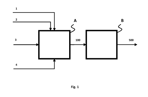
Fig. 1 illustrates a schematic layout of a first embodiment of a plant
A syngas stage
B synthesis stage
1 first feed (comprising hydrogen) to syngas stage
2 second feed (comprising carbon dioxide) to syngas stage
3 third feed (hydrocarbon which can be external to the plant
and/or internal
stream) to syngas stage
4 fourth feed (comprising oxygen) to syngas stage
100 syngas product from syngas stage
500 product from synthesis stage
Figure la illustrates a schematic layout of a first embodiment of a plant in
which the
hydrocarbon feed can be both from external sources or from the synthesis
stage, e.g. more
than one, for example three hydrocarbon streams from the synthesis stage.
Reference
numbers are for Figure 1, plus:
3a a part of third feed from external source (e.g. external
hydrocarbon stream
such as natural gas) to syngas stage
3b a part of third feed from synthesis stage (e.g. tail gas from F-
T) to syngas stage
3c another part of third feed from synthesis stage (e.g. LPG
stream from F-T) to
syngas stage
3d another part of third feed from synthesis stage (e.g. naphtha
stream from F-T)
to syngas stage
CA 03126620 2021-07-13
WO 2020/207926 PCT/EP2020/059598
28
Figure 2 illustrates a schematic layout of another embodiment of a plant, in
which the syngas
stage comprises a prereforming section (Ia) and an ATR section (I), and in
which steam as
fifth feed (5) is shown. Reference numbers are for Figure 1 and la, plus:
(Ia) prereforming section
(I) ATR section
la part of first feed to prereforming section
lb part of first feed to ATR section
5 fifth feed (steam)
prereformed hydrocarbon to ATR section
10 Figure 3 illustrates a schematic layout of another embodiment of a
plant, in which the syngas
stage comprises methanation section (II) and ATR section (I). The effluent
from methanation
section (II) is sent to ATR section (I). Reference numbers are as for the
previous figures,
plus:
(II) methanation section
30 effluent from methanation section to ATR section
Figure 3a illustrates a variation of the schematic layout, described in figure
3. In this
embodiment of a plant, hydrocarbon feeds are treated in prereforming section
(Ia) before
feeding it to methanation section (II) followed by ATR section (I). Fifth feed
steam (5) is
introduced to prereforming section.. Reference numbers are as for the previous
figures, plus:
20 prereformed hydrocarbon to methanation section
Figure 3b illustrates a variation of the schematic layout, described in figure
3a. This is an
embodiment of a plant with a part of the steam (5a) addition to is sent to
prereforming
section and another part of the steam (5b) addition to methanation section.
Reference
numbers are as for the previous figures, plus:
5a part of fifth feed to prereforming section
CA 03126620 2021-07-13
WO 2020/207926 PCT/EP2020/059598
29
5b part of the fifth feed to metha nation section
Figure 4 illustrates a schematic layout of another embodiment of a plant, in
which the syngas
stage comprises an rWGS section (III) plus an ATR section (I). Reference
numbers are as for
the previous figures, plus:
(III) rWGS section
1d part of first feed to section rWGS section
40 syngas stream from rWGS section (III)
Figure 4a illustrates a schematic layout of another embodiment of a plant, in
which the
syngas stage comprises an rWGS section (III) plus an ATR section (I). In this
layout, rWGS
section (III) and ATR section (I) are parallel to each other. Reference
numbers are as for the
previous figures, plus:
50 syngas stream from ATR section (I)
Figure 4b illustrates a schematic layout of another embodiment of a plant, as
per Figure 4a.
In the layout of Figure 4b, the syngas stream 50 from the ATR section (I) is
arranged to heat
the rWGS section (III). Effluent from ATR section (I) gets cooled to become
syngas stream
60 by exchanging heat with rWGS section and then is combined with the syngas
stream 40
from the rWGS section (III).
60 cooled syngas stream from ATR section (I) after cooling in rWGS
section (III)
Figures 4c corresponds to figure 4a, in which a methanation stage (II) is
present instead of
the rWGS section (III).
Figure 5 illustrates a schematic layout of another embodiment of a plant, in
which a
component recovery stage (C) - i.e. recycle of either hydrogen or more CO2 -
is present
between the syngas stage (A) and the synthesis stage (B). Reference numbers
are as for the
previous figures, plus:
C component recovery stage
150 recycle gas from component recovery stage
CA 03126620 2021-07-13
WO 2020/207926 PCT/EP2020/059598
200 syngas from component recovery stage
EXAMPLES
Various syngas stages are compared based on their effectiveness of utilizing
carbon
5 feedstock and energy. In recent years, CO2 emissions from such syngas
stages have also
been compared to minimize the environmental impact.
Conventionally, hydrocarbon-based feed is primarily used in syngas stage (A).
Typical values
of abovementioned distinguishing factors from such syngas stages, consisting
of autothermal
reformer (ATR) section (I), are shown in table 1.
10 In Cl, values from a conventionally designed hydrocarbon-based syngas
stage (A) without
CO2 feed are shown. In C2, some H2 and CO2 feed are used along with
hydrocarbon feed.
Hydrocarbon feed is still higher than CO2 feed. In C3, more CO2 and H2 feed
are used such
that CO2 feed consumption becomes higher than hydrocarbon feed consumption.
Table 1
Parameters Unit Cl C2
C3
H2 content in first feed (1) mol /0 N/A 99.0
99.0
CO2 content in second feed (2) mol /0 N/A 99.9
99.9
First feed (1)/second feed (2) N/A 2.97
2.97
External third feed (3a)/second feed (2) N/A 1.34
0.39
Fourth feed (4)/first feed (1) N/A 0.38
0.22
Fifth feed (5)/first feed (1) N/A 0.31
0.12
1-12/C0 in syngas product (100) 1.91 2.08
1.97
CO in syngas product (100)/ total C in feeds (both % 77.11
74.46 71.80
external and internal streams)
Relative CO2 emission in syngas stage (A)/1000 % 100.00 61.42
28.31
Nm3 (H2+CO) product
As it can be seen, CO2 emission improve with higher CO2 feed consumption.
However,
conversion is reduced to some extent.
This challenge can be solved by including methanation section (II) in addition
to the ATR
section (I) in the syngas stage (A). In table 2, the key parameters for the
syngas stage (A)
CA 03126620 2021-07-13
WO 2020/207926 PCT/EP2020/059598
31
are provided, wherein the syngas stage consists of a methanation section (II)
followed by an
ATR section (I). Syngas produced in the syngas stage (A) is fed to synthesis
stage (6),
comprising a Fischer-Tropsch synthesis section and product work-up section.
Some of the
recycle streams from synthesis stage (6) are used internally in the syngas
stage (A).
Table 2
Parameters Unit C4 C5
C6
H2 content in first feed (1) mol /0 99.0 99.0
99.0
CO2 content in second feed (2) mol /0 99.9 99.9
99.9
First feed (1)/second feed (2) - 4.95 4.51
4.01
External third feed (3a)/second feed (2) - 0.28 0.14
0.06
Fourth feed (4)/first feed (1) - 0.17 0.16
0.16
Fifth feed (5)/first feed (1) - 0.03 0.03
0.04
1-12/C0 in syngas product (100) - 2.41 2.18
1.95
CO in syngas product (100)/ total C in feeds (both % 80.80
80.60 79.68
external and internal streams)
Relative CO2 emission in syngas stage (A)/1000 % 0.00 0.00
0.00
Nm3 (H2+CO) product
In this concept no hydrocarbon combustion takes place and this there are no
CO2 emissions.
Specific net energy consumption in the syngas stage is estimated based on 1
Nm3 of (Hz +
CO) in the product stream. In table 1 and 2, relative CO2 emission is
estimated with respect
to CO2 emission in Cl as basis.
CA 03126620 2021-07-13
WO 2020/207926 PCT/EP2020/059598
32
The following numbered aspects are provided:
Aspect 1. A plant, said plant comprising:
a. a syngas stage, said syngas stage comprising an autothermal reforming (ATR)
section, and;
b. a synthesis stage;
said plant comprising:
- a first feed comprising hydrogen to the syngas stage;
- a second feed comprising carbon dioxide to the syngas stage;
- a third feed comprising hydrocarbons to the syngas stage, upstream of
said ATR
section; and
- a fourth feed comprising oxygen to the ATR section;
wherein said syngas stage is arranged to provide a syngas stream and feed said
syngas
stream to the synthesis stage.
Aspect 2. The plant according to aspect 1, wherein said third feed
comprising
hydrocarbons is fed to the syngas stage, directly upstream of said ATR
section.
Aspect 3. The plant according to any one of the preceding aspects,
wherein the syngas
stream is fed directly from the syngas stage to the synthesis stage.
Aspect 4. The plant according to any one of aspects 1-2, wherein the
plant comprises a
post-conversion section, located between said syngas stage and said synthesis
stage, and a
CO2 feed to said post-conversion section, arranged to be mixed with the syngas
stream
between the syngas stage and the post-conversion section.
Aspect 5. The plant according to any one of the preceding aspects,
further comprising a
fifth steam feed to the syngas stage.
CA 03126620 2021-07-13
WO 2020/207926 PCT/EP2020/059598
33
Aspect 6. The plant according to any one of the preceding aspects,
wherein said syngas
stage consists of said autothermal reforming (ATR) section, and wherein first,
second, third
and fourth feeds are fed to said ATR section.
Aspect 7. The plant according to any one of aspects 1-5, wherein the
syngas stage
additionally comprises a methanation section arranged upstream the ATR
section; wherein a
part or all of the first feed is fed to the methanation section; a part or all
of the second feed
is fed to the methanation section; and wherein a part or all of the third feed
is fed to the
syngas stage; upstream said methanation section and/or between said
methanation section
and said ATR section.
Aspect 8. The plant according to aspect 7, wherein the methanation section
comprises
two or more methanation units, such as three or more methanation units.
Aspect 9. The plant according to aspect 8, wherein parts of the first
feed comprising
hydrogen are fed separately to different methanation units in the methanation
section; or the
entire first feed comprising hydrogen is fed together to the methanation unit
located furthest
upstream in the methanation section.
Aspect 10. The plant according to any one of aspects 8-9, wherein parts of the
second feed
comprising carbon dioxide are fed separately to different methanation units in
the
methanation section; or the entire second feed comprising carbon dioxide is
fed together to
the methanation unit located furthest upstream in the methanation section.
.. Aspect 11. The plant according to any one of aspects 8-10, wherein parts of
the third feed
comprising hydrocarbons are fed separately to different methanation units in
the
methanation section; or the entire third feed comprising hydrocarbons is fed
together to one
methanation unit in the methanation section.
Aspect 12. The plant according to any one of aspects 8-11, wherein a part of
the effluent
from one methanation unit is cooled and recycled to the inlet of said
methanation unit and/or
to the inlet of any additional methanation units located upstream said one
methanation unit.
Aspect 13. The plant according to any one of aspects 1-5 and 7-12, wherein the
syngas
stage additionally comprises a reverse water gas shift (rWGS) section upstream
the ATR
section wherein a part or all of the first feed is fed to the rWGS section; a
part or all of the
second feed is fed to the rWGS section; and wherein a part or all of the third
feed is fed to
the syngas stage between said rWGS section (III) and said ATR section.
CA 03126620 2021-07-13
WO 2020/207926 PCT/EP2020/059598
34
Aspect 14. The plant according to aspect 13, wherein the rWGS section
comprises two or
more rWGS units, such as three or more rWGS units.
Aspect 15. The plant according to aspect 14, wherein parts of the first feed
comprising
hydrogen are fed separately to different rWGS units in the rWGS section; or
the entire first
feed comprising hydrogen is fed together to the reverse WGS unit located
furthest upstream
in the rWGS section.
Aspect 16. The plant according to any one of aspects 14-15, wherein parts of
the second
feed comprising carbon dioxide are fed separately to different rWGS units in
the rWGS
section; or the entire second feed comprising carbon dioxide is fed all
together to the rWGS
unit located furthest upstream in the rWGS section.
Aspect 17. The plant according to any one of the preceding aspects, wherein
the syngas
stream at the inlet of said synthesis stage has a hydrogen/carbon monoxide
ratio in the
range 1.00 ¨ 4.00; preferably 1.50 ¨ 3.00, more preferably 1.50 ¨ 2.10.
Aspect 18. The plant according to any one of the preceding aspects, wherein
the syngas
stream at the outlet of said syngas stage has a module, as defined above, in
the range 1.50
¨ 2.50; preferably 1.80 ¨ 2.30, more preferably 1.90 ¨ 2.20.
Aspect 19. The plant according to any one of the preceding aspects, wherein
the ratio of
H2:CO2 provided at the plant inlet is between 1.0 - 9.0, preferably 2.5 ¨ 8.0,
more preferably
3.0 ¨ 7Ø
Aspect 20. The plant according to any one of the preceding aspects, wherein
the synthesis
stage is a Fischer-Tropsch (F-T) stage, and wherein the ratio of H2:CO2
provided at the plant
inlet is in the range of 3.0-7.0 or more preferably from 3.0-6.0 and most
preferably 3.0-5Ø
Aspect 21. The plant according to any one of the preceding aspects, wherein
the first feed
consists essentially of hydrogen, i.e. over 75%, such as over 85%, preferably
over 90%,
more preferably over 95%, even more preferably over 99% of the first feed is
hydrogen.
Aspect 22. The plant according to any one of the preceding aspects, wherein
the second
feed consists essentially of carbon dioxide, i.e. over 75%, such as over 85%,
preferably over
90%, more preferably over 95%, even more preferably over 99% of the second
feed is
carbon dioxide.
CA 03126620 2021-07-13
WO 2020/207926 PCT/EP2020/059598
Aspect 23. The plant according to any one of the preceding aspects, wherein
said third
feed comprises one or more hydrocarbons selected from methane, ethane, propane
or
butane.
Aspect 24. The plant according to any one of the preceding aspects, wherein
said third
5 feed comprising hydrocarbons is a natural gas feed.
Aspect 25. The plant according to any one of the preceding aspects, wherein
said third
feed additionally comprises CO2 and/or CO and/or H2.
Aspect 26. The plant according to any one of the preceding aspects, wherein
the fourth
feed consists essentially of oxygen, i.e. over 75% such as over 90% or over
95%, such as
10 .. over 99% of the fourth feed is oxygen.
Aspect 27. The plant according to any one of the preceding aspects, wherein
the fourth
feed additionally comprises steam.
Aspect 28. The plant according to any one of the preceding aspects, wherein
the synthesis
stage is arranged to convert said syngas stream into at least a product stream
and,
15 optionally, a hydrocarbon-containing off-gas stream.
Aspect 29. The plant according to aspect 28, wherein at least a portion of
said
hydrocarbon-containing off-gas stream is fed to the syngas stage in addition
to said third
feed comprising hydrocarbons.
Aspect 30. The plant according to any one of the preceding aspects, wherein
the synthesis
20 .. stage is a Fischer-Tropsch (F-T) stage arranged to convert said syngas
stream into at least a
hydrocarbon product stream and a hydrocarbon-containing off-gas stream in the
form of an
F-T tail gas stream.
Aspect 31. The plant according to any one of the preceding aspects, wherein
the synthesis
stage is a Fischer-Tropsch (F-T) stage arranged to convert said syngas stream
into at least a
25 hydrocarbon product stream, being a diesel stream; and an LPG and/or a
naphtha product
stream, and wherein at least a portion of said LPG and/or a naphtha product
stream is fed to
the syngas stage in addition to said third feed comprising hydrocarbons.
CA 03126620 2021-07-13
WO 2020/207926 PCT/EP2020/059598
36
Aspect 32. The plant according to any one of aspects 1-31, in which the
synthesis stage
comprises at least one methanol synthesis stage arranged to provide at least a
methanol
product stream.
Aspect 33. The plant according to aspect 32, in which the synthesis stage
further
comprises a methanol-to-gasoline (MTG) synthesis stage arranged to receive the
methanol
product stream from the methanol synthesis stage and convert it to at least a
gasoline
stream and an LPG product stream, and wherein, optionally, a portion of said
LPG product
stream is fed to the syngas stage in addition to said third feed comprising
hydrocarbons.
Aspect 34. The plant according to any one of the preceding aspects, wherein ¨
when the
.. third feed is a LPG and/or a naphtha product stream or a natural gas feed ¨
said plant further
comprises a pre-reforming section, arranged in the third feed, upstream the
syngas stage.
Aspect 35. The plant according to aspect 34, wherein the hydrocarbon product
stream is an
LPG and/or a naphtha product stream from an F-T stage, and wherein said LPG
and/or
naphtha product stream is passed through said pre-reforming section prior to
being fed to
the syngas stage.
Aspect 36. The plant according to any one of aspects 34-35, wherein effluent
gas from the
ATR section is arranged to heat the pre-reforming section.
Aspect 37. The plant according to any one of the preceding aspects, further
comprising an
electrolyser arranged to convert water or steam into at least a hydrogen-
containing stream
and an oxygen-containing stream, and wherein at least a part of said hydrogen-
containing
stream from the electrolyser is fed to the syngas stage as said first feed
and/or wherein at
least a part of said oxygen-containing stream from the electrolyser is fed to
the syngas stage
as said fourth feed.
Aspect 38. The plant according to aspect 37, wherein the water or steam fed to
the
electrolyser is obtained from one or more units or stages in said plant.
Aspect 39. The plant according to any one of the preceding aspects, comprising
a sixth
feed of hydrogen to the syngas stream, upstream the synthesis stage.
Aspect 40. The plant according to aspect 39, wherein at least a part of said
hydrogen-
containing stream from the electrolyser is fed to the syngas stream, upstream
the synthesis
stage as said sixth feed of hydrogen.
CA 03126620 2021-07-13
WO 2020/207926 PCT/EP2020/059598
37
Aspect 41. The plant according to any one of aspects 31-40, wherein ¨ when the
third feed
is an off-gas stream ¨ said plant further comprises a hydrogenator arranged to
hydrogenate
the third feed, before said third feed enters the syngas stage.
Aspect 42. The plant according to any one of the preceding aspects, further
comprising a
hydrogen removal section, located between said syngas stage and said synthesis
stage, and
arranged to remove at least a part of the hydrogen from the syngas stream.
Aspect 43. The plant according to aspect 42, wherein at least a portion of the
hydrogen
removed from the syngas stream in said hydrogen removal section is compressed
and fed as
said first feed to the syngas stage.
Aspect 44. The plant according to any one of the preceding aspects, further
comprising a
carbon dioxide removal section, located between said syngas stage and said
synthesis stage,
and arranged to remove at least a part of the carbon dioxide from the syngas
stream.
Aspect 45. The plant according to aspect 44, wherein at least a portion of the
carbon
dioxide removed from the syngas stream in said carbon dioxide removal section
is
compressed and fed as said second feed to the syngas stage.
Aspect 46. The plant according to any one of the preceding aspects wherein the
ratio of
moles of carbon in the third feed comprising hydrocarbons, when external to
the plant, to the
moles of carbon in CO2 in the second feed is less than 0.3, preferably less
than 0.25 and
more preferably less than 0.2 or even lower than 0.1.
Aspect 47. The plant according to any one of the preceding aspects, wherein
the syngas
stage additionally comprises a reverse water gas shift (rWGS) section and a
methanation
section; and wherein the reverse water gas shift (rWGS) section is arranged
upstream the
methanation section and the methanation section is arranged upstream the ATR
section.
Aspect 48. The plant according to any one of the preceding aspects, wherein
- the syngas stage (A) comprises a methanation section (II) arranged in
parallel to said
ATR section (I);
- wherein at least a portion of the first feed (1) and at least a
portion of the second
feed (2) are arranged to be fed to the methanation section (II) and said
methanation
section (II) is arranged to convert said at least a portion of the first feed
(1) and at
least a portion of the second feed (2) to a first syngas stream (40);
CA 03126620 2021-07-13
WO 2020/207926 PCT/EP2020/059598
38
- wherein a third feed (3) comprising hydrocarbons and a fourth feed (4)
comprising
oxygen are arranged to be fed to the ATR section (I); and wherein said ATR
section
(I) is arranged to convert said third feed (3) comprising hydrocarbons and
said fourth
feed (4) comprising oxygen to a second syngas stream (50)
- wherein the first syngas stream (40) from the metha nation section (II)
is arranged to
be combined with the second syngas stream (50) from the ATR section (I); and
the
combined syngas stream (100) is arranged to be fed to the synthesis stage (B).
Aspect 49. The plant according to any one of the preceding aspects, wherein
- the syngas stage (A) comprises a reverse water gas shift (rWGS) section
(III)
arranged in parallel to said ATR section (I);
- wherein at least a portion of the first feed (1) and at least a portion
of the second
feed (2) are arranged to be fed to the rWGS section (III) and said rWGS
section (III)
is arranged to convert said at least a portion of the first feed (1) and at
least a portion
of the second feed (2) to a first syngas stream (40);
- wherein a third feed (3) comprising hydrocarbons and a fourth feed (4)
comprising
oxygen are arranged to be fed to the ATR section (I); and wherein said ATR
section
(I) is arranged to convert said third feed (3) comprising hydrocarbons and
said fourth
feed (4) comprising oxygen to a second syngas stream (50)
- wherein the first syngas stream (40) from the rWGS section (III) is
arranged to be
combined with the second syngas stream (50) from the ATR section (I); and the
combined syngas stream (100) is arranged to be fed to the synthesis stage (B).
Aspect 50. The plant according to aspect 48 or 49, wherein ¨ before combining
first and
second syngas streams, the second syngas stream (50) from the ATR section (I)
is arranged
to provide at least a part of the energy required for the endothermic reaction
in the rWGS
section (III).
Aspect 51. A method for producing a product stream, said method comprising the
steps of:
- providing a plant as defined in any one of the preceding aspects;
- supplying a first feed comprising hydrogen to the syngas stage;
- supplying a second feed comprising carbon dioxide to the syngas stage;
- supplying a third feed comprising hydrocarbons to the syngas stage, upstream
of said
ATR section;
CA 03126620 2021-07-13
WO 2020/207926 PCT/EP2020/059598
39
- supplying a fourth feed comprising oxygen to the ATR section;
- providing a syngas stream (100) in said syngas stage (A) from at least
said first,
second, third and fourth feeds, and feeding said syngas stream (100) to the
synthesis
stage (B);
- converting said syngas stream (100) into at least a product stream (500)
and a
hydrocarbon-containing off-gas stream (3b) in said synthesis stage (B); and
- optionally, feeding at least a portion of said hydrocarbon-containing off-
gas stream
(3b) to the syngas stage (I) in addition to said third feed (3) comprising
hydrocarbons; upstream of said ATR section (I).
Aspect 52. The method according to aspect 51, in which the synthesis stage is
a Fischer-
Tropsch (F-T) stage arranged to convert said syngas stream into at least a
hydrocarbon
product stream and a hydrocarbon-containing off-gas stream in the form of an F-
T tail gas
stream.
Aspect 53. The method according to any one of aspects 51-52, wherein the
content of
methane in the synthesis gas sent to the synthesis stage is less than 5%, such
as less than
3% or even less than 2%.
The present invention has been described with reference to a number of
features, aspects
and embodiments. These can be combined by the skilled person at will, within
the scope of
the present invention without departing from the scope of the invention as
defined in the
claims.