Note: Descriptions are shown in the official language in which they were submitted.
CA 03126923 2021-07-15
WO 2020/154090
PCT/US2020/012474
PACKAGING METHOD AND LINE FOR IMPROVED FINISHED PRODUCT
RELATED APPLICATION DATA
This application claims the benefit of US provisional application ser. no.
62/795,128, filed January 22, 2019, US non-provisional application serial no.
16/442,055, filed June 14, 2019, and US non-provisional application serial no.
16/674,294, filed November 5, 2019.
SUMMARY AND BACKGROUND
The disclosure is directed to a packaging line having an overwrap material
infeed station that is adapted and configured to package rolls or packs of
toilet tissue or
towels with an overwrap material which the seal that joins the two ends of the
overwrap
material may be formed on a horizontal face, vertical face or corner of the
tubular
package as desired. Thus, one machine is capable of forming the longitudinal
seal at
any position on a horizontal face, a vertical face, or at a corner of the
wrapped package
of the product, as desired. Although the description that follows below
involves the
wrapping and packaging of rolls, for instance, toilet tissue and paper towels,
the
principles of the disclosure may be used in connection with packaging lines
used for
packaging other products with an overwrap material where the seal location may
vary
depending upon product format. Further, the rolls or packs wrapped within the
overwrap material may be delivered to the overwrap infeed station in multiple
orientations and not limited to what is shown in the drawings.
BRIEF DESCRIPTION OF THE DRAWINGS
Figure 1 is a partial, perspective view of an embodiment of a portion of a
packaging line comprising an overwrap infeed station configured to receive
overwrap
material travelling in a generally horizontal format (the width is horizontal)
toward an
entrance of the overwrap infeed station and to apply a longitudinal seal to a
horizontal
face of a package of product wrapped with the overwrap material, the
horizontal face
1
CA 03126923 2021-07-15
WO 2020/154090
PCT/US2020/012474
being generally opposite of (at 180 degrees from) the side of the entrance to
which the
overwrap material is directed.
Figure 2 is a partial front view of the portion of the packaging line of
Figure 1
showing the package of the product to be wrapped with the overwrap material
entering
an entrance of the overwrap feed station where the seal to be applied to the
horizontal
face of the package of the product is generally opposite of (at 180 degrees
from) the
side of the entrance to which the overwrap material is directed.
Figure 3 is a partial top view of the portion of the packaging line of Figure
1 with
a top support of the overwrap station shown partially removed to provide
additional
detail of the wrapped product.
Figure 4 is a partial right side view of the portion of the packaging line of
Figure
1 with a side support of the overwrap station shown partially removed to
provide
additional detail of the wrapped product.
Figure 5 is a partial, perspective schematic view of the packaging line of
Figure
1 providing additional detail of the path of the overwrap material into the
entrance of the
overwrap feed station.
Figures 6 is a partial, perspective view of the portion of the packaging line
of
Figure 1 oriented in a second configuration in which the overwrap feed station
is rotated
90 degrees relative to the embodiment shown in Figure 1 but where the seal to
be
applied to the vertical face of the package of the product is generally
opposite of (at 180
degrees from) the side of the entrance to which the overwrap material is
directed.
Figure 7 is a partial, perspective schematic view of the packaging line of
Figure
6 providing additional detail of the path of the overwrap material into the
entrance of the
overwrap feed station.
Figure 8 is a partial, perspective view of another embodiment of a portion of
a
packaging line comprising an overwrap infeed station configured to receive
overwrap
material travelling in a generally horizontal format (the width is horizontal)
toward an
entrance of the overwrap infeed station and to apply a longitudinal seal to a
vertical face
2
CA 03126923 2021-07-15
WO 2020/154090
PCT/US2020/012474
of the package of product wrapped with the overwrap material, the vertical
face being
generally at 90 degrees (or 270 degrees) from the side of the entrance to
which the
overwrap material is directed.
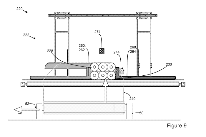
Figure 9 is a partial front view of the portion of the packaging line of
Figure 8
showing the package of the product to be wrapped with the overwrap material
entering
an entrance of the overwrap feed station where the seal to be applied to the
vertical
face of the package of the product is generally at 90 degrees (or 270 degrees
from)
from the side of the entrance to which the overwrap material is directed.
Figure 10 is a partial top view of the portion of the packaging line of Figure
8.
Figure 11 is a partial right side view of the portion of the packaging line of
Figure
8.
Figure 12 is a partial, perspective schematic view of the packaging line of
Figure
8 providing additional detail of the path of the overwrap material into the
entrance of the
overwrap feed station.
Figure 13 is a partial perspective top view of a portion of the packaging line
of
Figure 8.
Figure 14 is a partial, front view of another embodiment of a portion of a
packaging line comprising an overwrap infeed station configured to receive
overwrap
material travelling in a generally horizontal format (the width is horizontal)
toward an
entrance of the overwrap infeed station and to apply a longitudinal seal to a
package of
product wrapped with the overwrap material at a corner of the package (e.g.
adjacent a
transitional corner from the top to the right vertical side, for example at
135 degrees (or
225 degrees from) from the side of the entrance to which the overwrap material
is
directed).
DETAILED DESCRIPTION
Figures 1-5 generally show partial views of a packaging line 20 with an
overwrap feed station 22 in one configuration. Figures 6-7 generally show
partial views
of a packaging line 120 with an overwrap feed station 122 in another
configuration.
3
CA 03126923 2021-07-15
WO 2020/154090
PCT/US2020/012474
Figures 8-13 generally show partial views of a packaging line 220 with an
overwrap
feed station 222 in another configuration. Figure 14 shows a view of the
overwrap feed
station 322 in yet another configuration. Although not shown in all of the
views, the
packaging line overwrap feed station 22,122,222,322 generally has left and
right
vertical supports, and bottom and top horizontal supports that define an
enclosure with
a hollow interior for the overwrap feed station. For purposes of illustration,
Figures 3
and 4 show typical top supports 24 and right side supports 26 albeit in cut-
away to
provide additional detail of the product configuration as it is being wrapped.
Similar
supports may be provided on the left and bottom sides. For ease of
illustration, the
supports are otherwise not shown in the views of the Figures. Product
28,128,228,328
to be wrapped moves through the enclosure of the overwrap feed station
22,122,222,322 from an entrance 30,130,230,330 to a discharge 32,132,232 of
the
overwrap feed station.
The product 28,128,228,328 may move through the enclosure of the overwrap
feed station 22,122,222,322 via a conveyor, which may be integrated with the
enclosure. The conveyor may be a belt and/or roller conveyor. For purposes of
illustration and not in any limiting sense, Figures 3 and 4 show top and right
side belt
conveyors 34,36. Similar conveyors may be provided on the left and bottom
sides. For
ease of illustration, the conveyors are otherwise not shown in the views of
the Figures.
The product to be wrapped may also move through the enclosure via a vacuum or
through over pressure. The vacuum or over pressure may be coupled with
conveyor,
for instance, a belt and/or roller conveyor, which may be integrated with the
enclosure.
The product to be wrapped may also move through the enclosure with a pushing
or
pulling mechanism. In integrating the conveyor with the enclosure, the
conveyor may
be arranged on at least one of the left vertical support, right vertical
support, top
horizontal support, and bottom horizontal supports of the enclosure. To
provide even
feeding, the conveyor may be arranged on both vertical supports and/or both
horizontal
supports. There may be a part of the conveyor on the vertical supports for a
portion of
4
CA 03126923 2021-07-15
WO 2020/154090
PCT/US2020/012474
enclosure and part of the conveyor on the horizontal supports for another
portion of the
enclosure. In one aspect, driven belts grab the product as it enters into the
enclosure to
pull the product evenly with the overwrap material 40,140,240,340.
The overwrap feed station 22,122,222 receives at the entrance 30,130,230,330
the overwrap material 40,140,240,340 for the product 28,128,228,328 to be
packaged
in a tube of overwrap material. By way of example and not in any limiting
sense, the
overwrap material may be a polyethylene film. As the product 28,128,228,328 to
be
wrapped moves through the enclosure of the overwrap feed station
22,122,222,322 the
overwrap material 40,140,240,340 is drawn around the product to form a tube of
the
1.0 overwrap material around the product. As will be described in more
detail below, the
single overwrap feed station 22,122,222,322 may be configured in several
configurations depending upon the desired location of the longitudinal seal
used to form
the package containing the product 28,128,228,328.
In one configuration of the overwrap feed station 22,122, which is shown by
way
of example in Figures 1-7, the wrapped rolls or packs of products 28,128 may
have its
seal 42,142 on a face of the tubular package configuration which is generally
opposite
of (180 degrees from) the side of the entrance 30,130 of the overwrap feed
station to
which the overwrap material was directed, and more in particular, at the
center of the
face. The longitudinal seal 42,142 may be created by heating the adjacent and
overlapping longitudinal edges to fuse the edges to together and then
directing cooling
air over the fused edges to cure the seal. The seal 42,142 may also be created
by a fin
seal, or gluing or bonding the edges or flaps on the longitudinal edges of the
overwrap
material. The seal may also be created by ultrasonically welding the edges or
flaps on
the longitudinal edges of the overwrap material or by applying a heated
element directly
against the longitudinal edges of the film. Additionally, lasers could also be
used to
weld the edges together. A longitudinal seal unit 44,144 for forming the
desired seal
(e.g., heat, glue, ultrasonic, etc.) may be provided in the hollow interior of
the enclosure
on supports adjacent to the desired location of the seal.
5
CA 03126923 2021-07-15
WO 2020/154090
PCT/US2020/012474
Figures 1-5 show the overwrap material 40 being unwound from an unwind
stand 50 about a horizontal axis 52 and being directed to the entrance 30 of
the
overwrap feed station 22 from generally the bottom of the overwrap feed
station with a
width of the overwrap material being oriented horizontally. The longitudinal
seal unit 44
forms the seal adjacent to the top horizontal support of the overwrap feed
station 22 on
the top face of the package of wrapped product 28 which is generally opposite
of (180
degrees from) the bottom horizontal support and where the overwrap material
entered
the entrance to the overwrap feed station. Figures 6-7 show an alternate
embodiment
where the overwrap material 140 is being directed to the entrance 130 of the
overwrap
feed station 122 from generally the left side of the overwrap feed station (as
shown in
Figures or facing the entrance to the overwrap feed station). The longitudinal
seal unit
144 forms the seal 142 adjacent to the right vertical support of the overwrap
feed
station on the right vertical face of the package of wrapped product, which is
generally
opposite of (180 degrees from) the left vertical support and where the
overwrap material
entered the entrance to the overwrap feed station. While Figures 1-5 show the
unwind
stand 50 having a horizontal center axis 52 for unwinding, and the overwrap
material
travelling to the entrance of the overwrap feed station in a generally
horizontal format
(i.e., the width arranged horizontally), the overwrap material may be unwound
from the
unwind stand at an angle or vertically and may be oriented as desired prior to
being
guided into the entrance of the overwrap feed station with turn bars. For
instance, in
the embodiment of Figures 6-7, the overwrap material 140 may be unwound from
an
unwind stand (not shown) about a vertical axis so the overwrap material may
travel to
the entrance of the overwrap feed station in a generally vertical plane with
one
longitudinal edge vertically above the other across a width of the overwrap
material (i.e.,
the width of the overwrap material extending vertically). In the alternative
to that
described above relative to Figures 6 and 7, the overwrap material may be
unwound
from an unwind stand about a horizontal axis and may be initially directed to
the
entrance of the overwrap feed station in a generally horizontal format with
the
6
CA 03126923 2021-07-15
WO 2020/154090
PCT/US2020/012474
longitudinal edges of the overwrap material at the same vertical distance
across the
width (i.e., the width of the overwrap material extending horizontally), and a
45 degree
turn bar may be used to reorient the overwrap material prior to being guided
into the
entrance of the overwrap feed station.
In both embodiments of Figures 1-5 and 6-7, the overwrap material 40,140 may
be directed to the entrance of the overwrap feed station, and a former 60,160
arranged
around the entrance 30,130 of the overwrap feed station 22,122 may guide the
overwrap material into the hollow interior of the enclosure. As the overwrap
feed station
22,122 draws the overwrap material 40,140 into and through the hollow interior
of the
1.0 enclosure with the product 28,128 to be packaged, the former 60,160
manipulates the
overwrap material so that the opposite longitudinal edges of the overwrap
material
40,140 are brought adjacent to and overlapping with one another on a side of
the
overwrap feed station opposite of the side from which the overwrap material
was
directed to the entrance of the overwrap feed station, and more in particular,
at the
center of the respective face. Thus, the longitudinal seal unit 44,144 may be
arranged
(and the resultant longitudinal seal 42,142 may be formed) on the side of the
overwrap
feed station opposite of the side from which the overwrap material 40,140 was
directed
to the entrance 30,130 of the overwrap feed station, and may be placed on the
package
on the side of the package opposite of the side from which the overwrap
material was
directed to the entrance of the overwrap feed station. For instance, as best
shown in
Figure 5, the seal 42 is formed on the top face of the tubular package roughly
180
degrees from the center of the bottom face of the package which is the general
direction from which the overwrap material was directed to the entrance of the
overwrap
feed station. In Figure 7, the seal 142 is formed roughly 180 degrees from the
center of
the left face of the package which is the general direction from which the
overwrap
material was directed to the entrance of the overwrap feed station. Although
the
drawings show the seal being formed in the center of the top face of the
package, the
seal may be formed at any position on the horizontal or side face as may be
desired
7
CA 03126923 2021-07-15
WO 2020/154090
PCT/US2020/012474
with a former having a geometry configured to align the longitudinal edges of
the
overwrap material in the desired position.
In a second configuration of the packaging line 220 with an overwrap infeed
station 222, which is shown by way of example in Figures 8-13, the wrapped
rolls or
packs of products 228 may have its seal 242 on a vertical face of the tubular
package
configuration which is generally 90 degrees (or 270 degrees) from the side of
the
entrance 230 to which the overwrap material 240 was directed to the entrance
of the
overwrap feed station, and more in particular, at the center of the face. The
former 260
adjacent the entrance 230 of the overwrap feed station is adapted and
configured to
direct the overwrap material 240 for packaging the product to be packaged
through the
hollow interior of the enclosure with longitudinal edges of the overwrap
material
overlapping each other adjacent to one of the left and right vertical support.
Again, the
longitudinal seal 242 may be created by heating the adjacent and overlapping
longitudinal edges to fuse the edges to together and then directing cooling
air over the
fused edges to cure the seal, or using one of the aforementioned other
methods. A
longitudinal seal unit 244 may be provided in the hollow interior of the
enclosure on
supports adjacent to the desired location of the seal. For instance, Figures 8-
13 show
the overwrap material 242 being unwound from an unwind stand 50 about a
horizontal
axis 52 and being directed to the entrance of the overwrap feed station 230
from
generally the bottom of the overwrap feed station in a horizontal format. As
best shown
in Figure 8, the longitudinal seal unit 244 forms the seal 242 adjacent to the
right
horizontal support of the overwrap feed station 222 on the right face of the
package of
wrapped product. In the embodiment of Figures 8-13, the overwrap material 240
is
delivered to the entrance 230 of the overwrap feed station 222 in a manner
similar to
that shown in Figures 1-5, but the overwrap material comes together on a
vertical face
of the package rather than adjacent to the horizontal supports of the overwrap
feed
station.
8
CA 03126923 2021-07-15
WO 2020/154090
PCT/US2020/012474
The former of Figures 8-13 creates a very short path on one side of the
tubular
package of the product 228 (about 90 degrees from the side of the entrance of
the
overwrap feed station from which the overwrap material enters), and a much
longer
path around the other side of the tubular package of the product (about 270
degrees
from the side of the entrance of the overwrap feed station from which the
overwrap
material enters). To assist in moving the opposite longitudinal edges to
become
adjacent and overlapping with each other on a side 90 degrees from the side to
which
the overwrap material enters the overwrap feed station, the overwrap material
240 may
be significantly offset relative to the entrance 230 such that the
longitudinal edges
overlap on a side 90 degrees from the side to which the overwrap material
enters the
overwrap feed station. For instance, by way of example as shown in Figures 8-
13, the
overwrap material 240 may be unwound from an unwind stand 50 about a
horizontal
axis 52 and may be directed to the entrance 230 of the overwrap feed station
222 in a
generally horizontal format with the longitudinal edges of the overwrap
material at the
same vertical distance across the width (i.e., the width of the overwrap
material
extending horizontally), which is the general form of unwinding shown in
Figures 1-5.
However, in Figures 8-13, the relative position of the overwrap material 240
on the
unwind stand may be significantly shifted in the direction of the center axis
52 of unwind
stand 50 so that the overwrap material is guided to the entrance of the
overwrap feed
station significantly off center. In Figure 9, the roll of overwrap material
240 on the
unwind stand 50 has been shifted to the left. Thus, the same manner of
delivery of the
overwrap material and the same unwind stand may be used regardless of the
whether
the application process calls for the longitudinal seal to be formed on a
horizontal face
or vertical face of the tubular package. By way of example, the unwind stand
50 may
be placed be on linear rails and moved perpendicular to the direction of the
flow the
overwrap material 240 as it is being unwound from the stand. In a further
example, the
overwrap material 240 may be wound on a mandrel and the mandrel may be
disposed
on a spindle with the spindle disposed on a linear slide. The linear slide may
be
9
CA 03126923 2021-07-15
WO 2020/154090
PCT/US2020/012474
movable along a direction of the center axis 52 of the spindle between a
position in
which the overwrap material is centered relative to the entrance of the
overwrap feed
station and off center relative to the entrance of the overwrap feed station.
Thus, for
orientations of the longitudinal seal on the vertical face and the horizontal
face, the
same unwind stand 50 may be used and the overwrap material 40,140,240 may
follow
the same general flow path being fed underneath the overwrap feed station,
which is
out of the way and less inconvenient for an operator when operating the
overwrap feed
station. Although Figures 8-13 show the seal being formed in the center of the
side
face of the package, the seal may be formed at any position on the vertical
face as may
be desired with a former having a geometry configured to align the
longitudinal edges of
the overwrap material in the desired position.
For the ease of illustration, a single roll of overwrap film 140,240 is shown
on an
unwind stand 50. A double drum unwind stand may also be used to deliver the
over
wrap material to the overwrap feed station. The overwrap material may be
unwound
with either the overwrap material coming off the top of the roll or the bottom
of the roll.
When the application process calls for the seal to be oriented 180 degrees
from the
side to which the overwrap material enters the entrance of the overwrap feed
station,
the overwrap material may be centered on the unwind stand so it is generally
centered
to the former. When the application process calls for the seal to be oriented
90 degrees
(270 degrees) from the side to which the overwrap material enters the entrance
of the
overwrap feed station or at the corner, the overwrap material may be
significantly off
center on the unwind stand (e.g., shifted in the direction of the center axis
of rotation
during unwinding of the overwrap material on the unwind stand) so it is off
center to the
former. The position of the overwrap material relative to the entrance of the
former may
be shifted as necessary to allow the former to align the longitudinal edges of
the
overwrap material in the desired position on the top and/or side face of the
package.
The off center position of the overwrap material could be calculated in the
central
processing unit of the packaging line and moved automatically into position or
CA 03126923 2021-07-15
WO 2020/154090
PCT/US2020/012474
communicated to the operator through an operator interface. The tension of
overwrap
material as it is unwound from the double drum unwind stand may be monitored
and
changed using by way of example, a load cell, a dancer roller and a
potentiometer. A
measuring roller may be used to pull the overwrap material from the double
drum
unwind stand through the dancer roller and to feed the overwrap material
through the
former and the overwrap feed station at a desired speed. An eye mark reader
may be
used to synchronize the product delivered to the entrance of the overwrap feed
station
with the overwrap material so that a graphic material arranged on the overwrap
material
may be located in a desired position on the tubular package of wrapped
product.
When the product 28,128,228,328 is delivered to the entrance 30,130,230,333
of the overwrap feed station 22,122,222,322, the product is directed into the
overwrap
material at an opening in the former 60,160,260,360. The former 60,160,260,360
shapes the overwrap material 40,140,240,340 into a tube to enclose the bundled
product. The former 60,160,260,360 may comprise an assembly of plates or in
the
alternative, the former 60,160,260,360 may be a single, monolithic piece.
Additionally,
the former 60,160,260,360 may have adjustability to work with multiple formats
or it
could be specialized for one single product format. The former may also be
comprised
of cables or any other mechanical structure or mechanism to form a tube from a
web.
In one aspect of using the overwrap feed station, e.g., a first configuration
of the
overwrap feed station, a first former 60 may be used to guide the overwrap
material
through the entrance of the overwrap feed station such that the longitudinal
seal may be
formed on a horizontal face of the tubular package (for instance, as shown in
Figures 1-
5), and more in particular, at the center of the face. In another aspect of
using the
same overwrap feed station, e.g., a second configuration of the overwrap feed
station, a
second former 260 may be used to guide the overwrap material through the
entrance of
the overwrap feed station such that the longitudinal seal may be formed on a
vertical
face of the tubular package (for instance, as shown in Figures 8-13), and more
in
particular, at the center of the face. In another aspect of using the same
overwrap feed
11
CA 03126923 2021-07-15
WO 2020/154090
PCT/US2020/012474
station, e.g., a third configuration of the overwrap feed station, a third
former 360 may
be used to guide the overwrap material through the entrance of the overwrap
feed
station such that the longitudinal seal may be formed on a transitional corner
of the
tubular package (for instance, as shown in Figure 14). As mentioned above, the
former
may have a geometry as needed to place the seal in any position on the top
face or
side face, or at the corner of the package.
A former 60,160,260,360 may comprise a base 64,164,264,364 with a cap
portion 62,162,262,362. A base 64,164,264,364 of each of the formers
60,160,260,360
may be common but the cap portion 62,162,262,362 of each of the formers may be
1.0 differently shaped in order to manipulate the overwrap material
40,140,240,340 so that
the longitudinal edges of the overwrap material are arranged in an overlapping
and
adjacent manner on a desired location on the tubular package. The cap portion
62,162,262,362 of each of the formers 60,160,260,360 may cooperate with the
common base 64,164,264,364. In one example, there may be two sets of bases for
a
particular overwrap feed station. One base may be used when the process calls
for the
product to be delivered to the overwrap feed station in a "cores up" (standing
upright)
format, and the second base may be used when the process calls for the product
to be
delivered to the overwrap feed station in a "cores down" (laying down) format.
The first
base may be used regardless of the whether the overwrap feed station is in the
first
configuration or second configuration, and the second base may be used
regardless of
the whether the overwrap feed station is in the first configuration or second
configuration. Thus, the bases would not need to change based on longitudinal
seal
position, and first, second, and third configurations of the overwrap feed
station, but the
bases may change based on the incoming product orientation. In this example,
the cap
portions that work with particular base may change depending upon the
longitudinal
seal position and first, second and third configurations of the overwrap feed
station.
When the process calls for the longitudinal seal to be formed adjacent to the
top or
bottom horizontal supports, the cap portion of the former may use two top cap
plates
12
CA 03126923 2021-07-15
WO 2020/154090
PCT/US2020/012474
(one on each side, for instance, as shown in Figs. 1-5, '62'). In distinction,
when the
process calls for the longitudinal seal to be formed adjacent to the left or
right vertical
supports, the cap portion of the former may use one top plate (for instance,
as shown in
Figs. 8-13, '262'), and depending upon the application, a small, generally
straight,
second piece on the opposite side of the first portion (not shown). In yet
another
aspect, when the process calls for the longitudinal seal to be formed adjacent
to a point
of intersection of one of the left or right vertical supports with one of the
corresponding
top and bottom supports, the cap portion of the former 360 may use one top
plate (for
instance, as shown in Fig. 14, '362'), and depending upon the application, a
small,
generally straight, second piece on the opposite side of the first portion
(Fig. '364'). The
cap portions may also change based on the incoming product orientation ("cores
up"
format versus a "cores down" format). Thus, depending upon the overwrap feed
station
configuration and the incoming product orientation ("cores up" format versus a
"cores
down" format), the cap portion may be comprise multiple pieces to accommodate
different size products and different bundle configurations. Additionally it
is possible
that the base plates could be changed for different formats or longitudinal
seal position.
This may be done to optimize the quality of the bundle. That said, it is
preferred that
one base is compatible with the multiple cap portions so that when a
processing
application changes and the process calls for a different longitudinal seal
position but
the same product orientation, switching between the first and second
configurations of
the overwrap feed station merely involves swapping out the cap portions, and
to the
extent necessary, shifting the position of the unwind stand, as described
above.
By way of example (see, e.g., the embodiment shown in Figures 1-5), for the
former used to form the longitudinal seal in the center of the top face (e.g.,
the face 180
degrees from the side to which the overwrap material 40 enters the entrance of
the
overwrap feed station) with a "cores up" orientation of the product 28, the
base 64 may
comprise two base plates and the cap portion 62 may comprise two cap plates.
The
overwrap material wraps 40 equally around each side of the former 60 based on
13
CA 03126923 2021-07-15
WO 2020/154090
PCT/US2020/012474
product width and product height. The former 60 is shaped such that the
opposite
longitudinal edges of the overwrap material come together at a point 180
degrees
relative to the incoming path of the overwrap material into entrance of the
overwrap
feed station. In the embodiment of Figures 1-5, the base plates may be moved
laterally
apart and the cap plates may be moved laterally apart the same distance to
accommodate a different product width. The lateral spacing between the two cap
plates and the lateral spacing between the two base plates (as well as the
lateral
spacing between the side pull belts on the conveyor) may be adjustable by use
of a
hand wheel, a motor driven slide, pneumatic actuator, or mechanical spacers.
In a
similar manner, the cap plates may be moved vertically relative to the base
plates to
accommodate a different product height. The vertical spacing between the two
cap
plates and the two base plates (as well as the vertical spacing between the
upper and
lower pull belts) may be adjustable by use of a hand wheel, a motor driven
slide,
pneumatic actuator, or mechanical spacers. In this example, the pull belts may
be
extended into the former opening to receive the product. Since both sides of
the former
have space inside, the pull belts can grab evenly to receive the product and
overwrap
material and pull it through the former. Thus, depending upon the size of the
product,
the same former plates may be used for different wrapped product format sizes
having
a longitudinal seal 180 degrees from the side to which the overwrap material
enters the
entrance of the overwrap feed station. Should the process change and call for
a "cores
down" orientation of the product, a new base may be used and a new cap portion
may
be used, each functioning in a way similar to that described above.
By way of example (see, e.g., the embodiment shown in Figures 8-13), for the
former 260 used to form the longitudinal seal in the center of the right
vertical face (e.g.,
the face at 90 degrees (270 degrees) from the side to which the overwrap
material
enters the entrance 230 of the overwrap feed station) in a "cores down"
orientation of
the product 228, the base 264 may comprise two base plates and the cap portion
262
may comprise one cap plate. The former 260 is shaped such that the opposite
14
CA 03126923 2021-07-15
WO 2020/154090
PCT/US2020/012474
longitudinal edges of the overwrap material come together at a point 90
degrees (270
degrees) relative to the incoming path of the overwrap material 240 into
entrance 230 of
the overwrap feed station 222. In another of example (see, e.g., the
embodiment
shown in Figure 14), for the former 360 used to form the longitudinal seal in
the
transition corner (e.g., point of intersection between one of the top and
bottom
horizontal supports and one of the corresponding left and right vertical
supports (135
degrees/225 degrees from the side to which the overwrap material enters the
entrance
330 of the overwrap feed station) in a "cores down" orientation of the product
328, the
base 364 may comprise two base plates and the cap portion 362 may comprise one
cap plate. The former 360 is shaped such that the opposite longitudinal edges
of the
overwrap material come together at the corner of the package. In the
embodiment of
Figures 8-13 and the embodiment of Figure 14, the base plates may be moved
laterally
apart and a different cap plate may be used to accommodate different product
widths,
heights, and diameters. The lateral spacing between the two base plates (as
well as
.. the lateral spacing between the side pull belts on the conveyor) may be
adjustable by
use of a hand wheel, a motor driven slide, or pneumatic actuator. The vertical
spacing
between the cap plate and the two base plates (as well as the vertical spacing
between
the upper and lower pull belts) may be adjustable by use of a hand wheel, a
motor
driven slide, pneumatic actuator, or mechanical spacers. In this example, the
pull belts
may be extended into the former on only one side of the opening to receive the
product.
Because the other side of the former is generally open and the seal unit or
heater is
arranged in that position to apply the longitudinal seal, the pull belts on
the side of the
longitudinal seal unit or heater may be retracted out of the way. A lost
motion design
may be used to accommodate the space. Multiple former pieces may also be used,
and changing from one mode to the other may involve manual or automated
assembly
of the former pieces. Automated assembly may be accomplished via pneumatic or
motorized actuators. Additionally, a secondary assembly may be mounted in
front (i.e.,
upstream) of the location of and on the same side as the longitudinal sealer
to help
CA 03126923 2021-07-15
WO 2020/154090
PCT/US2020/012474
receive and contain the product as it enters the former. As seen in Figure 8,
there is a
significant gap between the top and bottom plate on the right side, and a
secondary
assembly may be used to capture that product and help move it through the
former.
The secondary assembly may be a small belt assembly driven from other belts in
the
area. The secondary assembly may also comprise a small guide plate with roller
wheels or beads. The secondary assembly may comprise a housing with a drive
for
driving a set of smaller belts integrated with the longitudinal seal unit.
Alternatively, as
shown in Figure 13, a belt driven assembly 270 may be moved in a direction
laterally
toward the product flow and the opening of the former into the gap between the
top and
.. bottom plate 262,264 on the right side of the former 260. For a
configuration as shown
in Figures 1-7, the belt driven assembly may be moved in a direction toward
the inlet of
the former to capture the product as soon as possible. In the configuration as
shown in
Figures 8-13, the belt driven assembly 270 may have sections 272 that are
arranged to
create a lateral spacing between the belt and the product which allows the
bottom part
of the cap plate (e.g., the portion extending downward just before the seal
unit) to fit
between product and the belt of the belt driven assembly 270. The section 272
(and
thus the spacing) may be adjustable in width or position to accommodate
different sizes
of cap plates and bottom plates, and different product sizes and formats. The
belt
driven assembly may reduce the number of different parts required for
different product
sizes and formats, and may reduce set-up time in changing the packaging line
and
overwrap feed station from one format to another. Thus, depending upon the
height of
the product, the same cap plate and base plates may be used for different
wrapped
product format height sizes having a longitudinal seal 90 degrees (270
degrees) from
the side to which the overwrap material enters the entrance of the overwrap
feed
station. Should the process change and call for a "cores up" product
orientation, a new
base may be used and a new cap portion may be used, each functioning in a way
similar to that described above.
16
CA 03126923 2021-07-15
WO 2020/154090
PCT/US2020/012474
A third configuration of the packaging line 320 with an overwrap infeed
station
322 is shown by way of example in Figure 14. The wrapped rolls or packs of
products
328 have its seal 342 on a corner of the tubular package configuration which
is
generally 90 degrees (or 270 degrees) from the side of the entrance 230 to
which the
.. overwrap material 240 was directed to the entrance of the overwrap feed
station. The
former 360 adjacent the entrance 330 of the overwrap feed station is adapted
and
configured to direct the overwrap material 340 for packaging the product to be
packaged through the hollow interior of the enclosure with longitudinal edges
of the
overwrap material overlapping each other adjacent to the corner of the left
and right
vertical support. Again, the longitudinal seal 342 may be created by heating
the
adjacent and overlapping longitudinal edges to fuse the edges to together and
then
directing cooling air over the fused edges to cure the seal, or using one of
the
aforementioned other methods. A longitudinal seal unit 344 may be provided in
the
hollow interior of the enclosure on supports adjacent to the desired location
of the seal.
For instance, Figure 14 shows the overwrap material 342 being unwound from an
unwind stand 50 about a horizontal axis 52 and being directed to the entrance
of the
overwrap feed station 330 from generally the bottom of the overwrap feed
station in a
horizontal format. The longitudinal seal unit 344 forms the seal 342 adjacent
to the right
horizontal support of the overwrap feed station 322 on the top right corner of
the
package of wrapped product. In the embodiment of Figure 14, the overwrap
material
340 is delivered to the entrance 330 of the overwrap feed station 222 in a
manner
similar to that shown in Figures 1-5, but the overwrap material comes together
on the
top corner of the package rather than adjacent to the horizontal supports of
the
overwrap feed station.
The former of Figure 14 is similar to the former of Figure 8-13 and creates a
very short path on one side of the tubular package of the product 328 (about
135
degrees from the side of the entrance of the overwrap feed station from which
the
overwrap material enters), and a much longer path around the other side of the
tubular
17
CA 03126923 2021-07-15
WO 2020/154090
PCT/US2020/012474
package of the product (about 225 degrees from the side of the entrance of the
overwrap feed station from which the overwrap material enters). To assist in
moving
the opposite longitudinal edges to become adjacent and overlapping with each
other on
the corner of the package (e.g., a side 135 degrees from the side to which the
overwrap
material enters the overwrap feed station), the overwrap material 340 may be
significantly offset relative to the entrance 330 such that the longitudinal
edges overlap
on a side 135 degrees from the side to which the overwrap material enters the
overwrap feed station. For instance, by way of example as shown in Figure 14,
the
overwrap material 340 may be unwound from an unwind stand 50 about a
horizontal
.. axis 52 and may be directed to the entrance 330 of the overwrap feed
station 322 in a
generally horizontal format with the longitudinal edges of the overwrap
material at the
same vertical distance across the width (i.e., the width of the overwrap
material
extending horizontally), which is the general form of unwinding shown in
Figures 1-5.
However, in Figure 14 (like in Figures 8-13), the relative position of the
overwrap
material 340 on the unwind stand may be significantly shifted in the direction
of the
center axis 52 of unwind stand 50 so that the overwrap material is guided to
the
entrance of the overwrap feed station significantly off center. In Figure 14,
the roll of
overwrap material 340 on the unwind stand 50 has been shifted to the left. By
way of
example, as described above with reference to the configuration of Figures 8-
13, the
unwind stand 50 may be placed be on linear rails and moved perpendicular to
the
direction of the flow the overwrap material 340 as it is being unwound from
the stand.
The amount of shift may be less than that needed for a side lap seal, for
instance, as
shown in Figure 8-13, given the same product and film size. This provides an
advantage in reducing space and the overall footprint of the machine range as
the
same manner of delivery of the overwrap material and the same unwind stand may
be
used regardless of the whether the application process calls for the
longitudinal seal to
be formed on a horizontal face, vertical face, or corner of the tubular
package.
18
CA 03126923 2021-07-15
WO 2020/154090
PCT/US2020/012474
The configuration of Figure 14 may provide more flexibility over the
configurations for Figures 1-5, 6-7 and 8-13, in allowing for a relatively
larger area on
the package for graphics depending upon the product format, particularly, with
a "cores
down" format where the rolls provide a roll radius in which to place the seal.
In the configurations of Figures 1-5, 6-7, and 8-13, a flat surface or a flat
backing
plate may be used to create a barrier between the overwrap material and the
rolls being
packaged so that when the longitudinal edges of the overwrap film are sealed,
they are
not welded to the rolls or a film used to contain inner packages of the rolls.
In the
embodiment of Figure 14, a backing plate may be provided that is formed to
match the
radius or corner of the rolls. In the alternative, a flexible member may be
provided. The
flexible member may be deflectable/formable to form to the required corner
shape and
provide the necessary backing for the seal without needing to change parts
from one
format to the next, which may be advantageous reduce changeover time, part
count,
and cost.
Generally speaking, in the embodiments of Figures 1-7, 8-13, and 14, the
longitudinal seal 44,144,244,344 unit may be manually or automatically
adjusted for
height and may be manually or automatically adjusted in the direction of the
movement
the product as it is being moved through the hollow interior of the enclosure.
One
longitudinal seal 44,144,244,344 unit may be provided and may be oriented as
needed
to provide the longitudinal seal on the desired side of the package. The
longitudinal
seal 44,144,244,344 unit may be disposed on a mechanism that moves from a
position
adjacent the top horizontal support of the overwrap feed station and to a
position
adjacent one of the left and right vertical supports of the overwrap feed
station. The
longitudinal seal unit may be configured to move to any position relative to
the
horizontal and vertical faces, and the corner to allow the longitudinal seal
to be formed
as desired. The movement could be performed by a motorized assembly that
allows
the longitudinal seal unit 44,144,244,344 to pivot to either location and to
move in a
secondary actuation direction that allows the longitudinal seal unit to be
brought to a
19
CA 03126923 2021-07-15
WO 2020/154090
PCT/US2020/012474
close distance to the path of the overwrap material 40,140,240,340. The index
movement may be performed manually or via a rotary actuator. Alternatively, a
second
longitudinal seal unit (see, e.g, Figs. 8-13, '274') may be provided with one
longitudinal
seal unit 274 arranged adjacent the top horizontal support of the overwrap
feed station
and used for applying the longitudinal seal at any position on the horizontal
face of the
package (e.g., 180 degrees from the side to which the overwrap material enters
the
entrance of the overwrap feed station) and the other longitudinal seal unit
244 arranged
adjacent the left and/or right vertical horizontal support of the overwrap
feed station and
used for applying the longitudinal seal at any position on the vertical face
of the
.. package (e.g., 90 degrees (270 degrees) from the side to which the overwrap
material
enters the entrance of the overwrap feed station). The longitudinal seal unit
that is not
used for the application process may be moved to a disengaged position. For
instance,
as shown in Figures 8-13, the second longitudinal seal unit 274 is moved out
of
position. For desired movement or disengagement from use, a longitudinal seal
unit
may be moved manually, with a motor driven slide, or via pneumatic actuator.
During normal operation of the packaging line 20,120,220,320 and overwrap
feed station 22,122,222,322 the overwrap material 40,140,240,340 is directed
from the
unwind stand 50, pulled around the outside of the former 60,160,260,360 and
then
through an opening of the former into the entrance 30,130,230,330 of the
overwrap
feed station to form a tube around the product 28,128,228,328 and the tube of
overwrap
material around the product is sealed by the longitudinal sealer (not shown).
A vacuum
lance (not shown) may be used to extract any air from the bundle that was
introduced
and as a backing for formation of the longitudinal seal preventing the
overwrap material
from melting onto the product during heating to form the longitudinal seal.
Additionally,
a passive means of allowing the air to exit the bundle may be used, such as
holes
punched in the film upstream. The upper and lower end seal dies (not shown)
may be
disposed at the discharge 32,132,232,332 of the overwrap feed station
22,122,222,322
to form end seals in the tubular wrapped product. Mechanical tuckers (not
shown) or
CA 03126923 2021-07-15
WO 2020/154090
PCT/US2020/012474
an air blast (not shown) may be disposed at the discharge 32,132,232,332 of
the
overwrap feed station 22,122,222,322 to form the gussets in the tubular
package. A
plunge knife (not shown), or a knife that is either mechanically or
pneumatically
actuated (not shown), may be disposed at the discharge 32,132,232,332 of the
overwrap feed station 22,122,222,322 to cut adjacent bundles of the tubular
packages
at the end seals. A separate cut and seal ribbon may also be used to separate
the tube
and seal the ends together.
As is evident from the foregoing description, a single overwrap feed station
may
be arranged in multiple alternative configurations to allow the user to place
the
longitudinal seal at different positions on the horizontal and side faces, and
the corner
of the package. It should be realized that a former may be configured to
arrange the
seal at any position on the horizontal or vertical face of the package,
including the
corner of the package, and that the overwrap material may be positioned as
needed (for
instance, by moving the unwind stand) to facilitate locating overlapping edges
of the
overwrap material as desired at any position on the horizontal or vertical
face of the
package, including the corner of the package.
Further embodiments can be envisioned by one of ordinary skill in the art
after
reading this disclosure. In other embodiments, combinations or sub-
combinations of
the above-disclosed invention can be advantageously made. The example
arrangements of components are shown for purposes of illustration and it
should be
understood that combinations, additions, re-arrangements, and the like are
contemplated in alternative embodiments of the present invention. Thus,
various
modifications and changes may be made thereunto without departing from the
broader
spirit and scope of the invention as set forth in the claims and that the
invention is
intended to cover all modifications and equivalents within the scope of the
following
claims
21