Note: Descriptions are shown in the official language in which they were submitted.
HYDRAULICALLY-POWERED VEHICLE LEVELER
10
FIELD OF THE INVENTION
This invention relates to vehicle levelers and more particularly to a vehicle
leveler having multiple surface angles as well as a leveler being
hydraulically-
powered for operation.
BACKGROUND OF THE INVENTION
A variety of truck levelers have been devised to adjust the height of
different
trailers to properly match the deck of the trailer to the height of the dock.
By aligning
the height of the trailer and the dock the loading and unloading of cargo is
facilitated.
One such device is seen in U.S. Patent No. 4,624,446 to Gould which
discloses a reinforced platform pivotally mounted to the ground at one end and
includes a support assembly having hydraulic cylinders. In operation the
rearwheels
of a truck trailer are backed onto the platform and then the non-mounted end
of the
platform is lifted by the hydraulic cylinders until the deck of the trailer is
equal to the
height of the dock.
A similar device is shown in U.S. Patent No. 4,765,792 to Cherry, et al. which
also discloses a pivotally-mounted and hydraulically-raised platform. In
addition to
the disclosure of Gould, the device includes mounting the hydraulics inwardly
from
the non-mounted end of the platform and an aperture in the non-mounted end of
the
platform to accommodate a truck restraining device.
1
Date Recue/Date Received 2021-08-06
Another design is disclosed in U.S. Patent No. 6,368,043 to Leum, et al. which
teaches a low-profile truck leveler. In this design a low-profile leveler is
enabled
through the use of a raised rear beam and two lateral beams that extend above
the
upper surface of the platform. In addition, a central beam adds further to the
strength
and rigidity of the leveler.
Vehicle levelers of the prior art typically have certain disadvantages. The
majority of vehicle levelers have ramp surfaces which are not highly
adjustable; this is
a distinct disadvantage when vehicles are being loaded or unloaded with cargo.
Levelers of the prior art are also not able to accommodate all types of
vehicles. This
is yet another disadvantage.
Some levelers of the prior art have certain shortcomings and disadvantages to
which this device is drawn. Specifically, it would be advantageous to have a
vehicle
leveler which is highly adjustable and can elevate both the rear and front
axles of a
vehicle at the same time so as to minimize the slope of the internal floor of
the vehicle
and thereby allow safer loading and unloading of cargo. It would also be
advantageous to have a vehicle leveler which is powered by both a battery and
a
hydraulic system.
In summary, there are problems and shortcomings in the prior art vehicle
levelers and it is to these needs that this device is drawn.
OBJECTS OF THE INVENTION
It is an object of this invention to provide a vehicle leveler which is highly
adjustable and can elevate both the rear and front axles of a vehicle at the
same time
so as to minimize the slope of the internal floor of the vehicle or trailer.
Another object of this invention is to provide a vehicle leveler which has a
power unit with a battery and a hydraulic system.
These and other objects of the invention will be apparent from the following
descriptions and from the drawings.
2
Date Recue/Date Received 2021-08-06
SUMMARY OF THE INVENTION
The preferred embodiment of the invention includes a vehicle leveler for use
with a driveway includes a first portion having a leading edge and a trailing
edge, the
trailing edge is disposed further from the driveway than the leading edge and
forms a
ramp section, the first portion having a flat section adjacent the trailing
edge, the flat
section being disposed about parallel with the substantially flat driveway.
The second
portion also includes an extension portion which extends from the trailing
edge of the
second portion toward the rear of the leveler and includes a substantially
flat section
disposed about parallel with the substantially flat driveway. The first
portion and
second portion are each unitary structures which are separate from each other
until
they are removably attached together by a connection apparatus. It is highly
preferable that the vehicle leveler includes opposing side portions which
extend the
length of and contact the second portion and extension portion, the opposing
side
portions having a top surface which forms a walkway.
In highly preferred applications, two or more vehicle levelers can be
installed
adjacent to each other and an extended walkway surface can be removably
installed
between each vehicle leveler to form a large surface for a vehicle driver to
use. It is
preferable that the extended walkway surface and top surface form a large
walkway
for a vehicle driver. In some preferred embodiments each vehicle leveler has
two,
opposing top surfaces which each form a separate walkway. The walkway can
extend
the complete length of the top surface in some preferred embodiments or it can
only
extend a portion of the length of the top surface.
Preferably, the walkway and extended walkway surface include metal grading
for safe contact surface for a vehicle driver walking on the walkway or
extended
walkway surface.
The first portion and second portion are each preferably unitary structures
which are separate from each other until they are removably attached together
by a
connection apparatus. It is highly preferred that the second portion including
the
extension portion can be moved between a lowered position and a raised
position to
accommodate varying dock heights for loading and unloading of cargo from
vehicles.
3
Date Recue/Date Received 2021-08-06
It is also preferable that the ramp section can be of varying lengths and
heights to
accommodate a single, rear axle vehicle as well as a large trailer.
Highly preferred embodiments include a power unit being a battery and a
hydraulic system that allows movement of the first portion and second portion.
Preferably, the battery can be charged by a solar panel or the battery can be
charged by
a power supply from within a building. It is preferable that the power supply
has a
current draw which is lower than a current draw from a power supply unit with
an AC
motor.
In some preferred embodiments, the battery powers a 12 volt direct current
power system which requires a large amount of power for a short period of
time. It is
also preferred that the battery can be charged over a period of time with a
lower power
requirement from the building, thereby allowing use of a 120 volt 15 amp
circuit to
power a dock door.
Another preferred embodiment includes a vehicle leveler for use with a
substantially flat driveway, the leveler is capable of movement between a
lowered
position and a raised position, the leveler in the lowered position has a
first portion
with a leading edge at a front of the leveler and a substantially flat
section; the
substantially flat section is inclined from the substantially flat driveway at
between
about 1 and 15 degrees from parallel with the substantially flat driveway. A
second
.. portion extends from the incline portion toward a rear of the leveler and
includes a
substantially flat section; the substantially flat section is declined toward
the
substantially flat driveway at between about 1 and 15 degrees from parallel
with the
substantially flat driveway. An extension portion extends from the second
portion
toward a rear of the leveler and includes a substantially flat section
disposed about
parallel with the substantially flat driveway and opposing side portions
extend the
length of and contact the first portion, second portion and extension portion,
the
opposing side portions have a top surface which forms a walkway. It is highly
preferable that a power unit includes a battery and a hydraulic system, the
powerunit
provides power and allows movement of the first portion and second portion.
In some preferred embodiments, the battery is charged by a solar panel. In
other preferred embodiments, the battery is charged by a power supply from
within a
4
Date Recue/Date Received 2021-08-06
building. Some preferred embodiments can incorporate both a power supply from
within a building as well as a solar panel.
Preferably, the power supply has a current draw which is lower than a current
draw from a power supply unit with an AC motor. It is preferred that the
battery
powers a 12 volt direct current power system which requires a large amount of
power
for a short period of time. The battery can be charged over a period of time
with a
lower power requirement from the building, thereby allowing use of a 120 volt
15
amp circuit to power a dock door.
BRIEF DESCRIPTION OF THE DRAWINGS
The drawings illustrate preferred embodiments including the above-noted
characteristics and features of the device. The device will be readily
understood from
the descriptions and drawings. In the drawings:
FIGURE 1 is a perspective view of the vehicle leveler;
FIGURE 2 is a top view of the vehicle leveler in FIGURE 1;
FIGURE 3 is a perspective view of the vehicle leveler of FIGURE 1 with a
truck on the leveler and the leveler in the lowered position;
FIGURE 4 is a perspective view of the vehicle leveler of FIGURE 1 with a
truck on the leveler and the leveler in the raised position;
FIGURES 5-6 are perspective views of the vehicle leveler in the raised
position;
FIGURE 7 is a perspective view of the vehicle leveler of FIGURE 1 in the
lowered position with a trailer on the leveler;
FIGURE 8 is a perspective view of the vehicle leveler of FIGURE 1 with a
vehicle driver using the top surface/walkway;
FIGURE 9 is a top view of the vehicle leveler illustrating the top
surface/walkway extending partially along the length of the leveler;
FIGURE 10 is a top view of the vehicle leveler illustrating the top
surface/walkway extending farther along the length of the leveler;
FIGURE 11 is a front view of the leveler illustrating the opposing side
portions and extended walkway surface;
5
Date Recue/Date Received 2021-08-06
FIGURE 12 is a front view of the extended walkway surface;
FIGURE 13 is a front view of two levelers installed side-by-side and
illustrating the large walkway;
FIGURE 14 is a top view illustrating four vehicle levelers installed adjacent
to
each other with a large walkway in between the levelers;
FIGURE 15 is a perspective view of the vehicle leveler with a hydraulic power
source and a solar panel power source;
FIGURE 16 is a front view of the power source including a battery and
hydraulic system;
FIGURE 17A and 17B are an electrical schematic for the control box;
and FIGURE 18 is an electrical schematic for the power unit.
DETAILED DESCRIPTION OF PREFERRED EMBODIMENTS
A preferred embodiment of the present invention is shown in FIGURES 1-18.
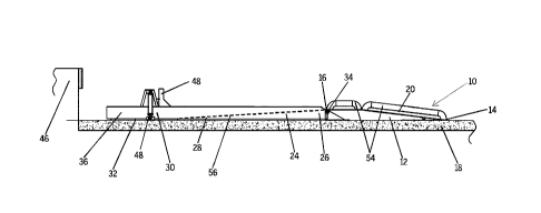
The vehicle leveler 10, as shown in FIGURE 1, includes three primary portions,
a first
portion 12, a second portion 24 and an extension portion 30 and is designed to
be
utilized in conjunction with a substantially flat driveway 18 near a loading
dock wall
46. Furthermore, the leveler 10 can be moved between a lowered position 36,
shown
in FIGURES 1 and 3 and a raised position 38, shown in FIGURES 4-6.
First portion 12 has a ramp section 20 which is inclined upwards and a flat
section 22 adjacent ramp section 20. First portion 12 includes a leading edge
14 and a
trailing edge 16. Trailing edge 16 is disposed further from driveway 18 than
leading
edge 14. Trailing edge 16 is part of flat section 22. Flat section 22 is
disposed about
parallel with substantially flat driveway 18.
FIGURE 1 illustrates that second portion 24 has a leading edge 26 and a
trailing edge 28. Leading edge 26 of second portion 24 is removably attached
to
trailing edge 16 of first portion 12 as seen in FIGURES 1, 3-4. FIGURE 5
illustrates
that first portion 12 and second portion 24 are removable attached as it shows
first and
second portions 12, 24 separated. Leading edge 26 of second portion 24 is
disposed
further from driveway 18 than trailing edge 28 of second portion 24.
6
Date Recue/Date Received 2021-08-06
Second portion 24 also includes an extension portion 30 as can be seen in
FIGURES 1-7. Extension portion 30 extends from trailing edge 28 of second
portion
24 toward a rear of the leveler 10 (nearest the loading dock wall 46) and
includes a
substantially flat section 32 disposed about parallel with the substantially
flat
driveway 18.
FIGURE 2 illustrates that first 12 and second portions 24 include metal
grading 42 over a steel plate for contact with wheels of a vehicle as the
vehicle moves
onto and off of leveler 10. Metal grating 42 over a steel plate is a material
which is
both durable and also provides increased traction for vehicles when moving
onto or
off of leveler 10.
FIGURES 1-7 illustrate that first portion 12 and second portion 24 are each
unitary structures which are separate from each other as seen in FIGURE 5
until they
are removably attached together by a connection apparatus 34 as seen best in
FIGURES 1 and 3-4. Connection apparatus 34 is located on leading edge 26 of
second portion 24 and connects to trailing edge 16 of first portion 12. Flat
section 22
of first portion 12 is in front of connection apparatus 34 since connection
apparatus 34
is located on leading edge 26 of second portion 24.
The drawings illustrate that second portion 24 including extension portion 30
can be moved between a lowered position 36 as seen in FIGURES 1, 3 and 7 and a
raised position 38 a seen in FIGURES 4-6, to accommodate varying dock heights
for
loading and unloading of cargo from vehicles. FIGURES 4-7 show a variety of
different types of vehicles which can utilize leveler 10.
Depending on the length of the vehicle, leveler 10 can be customized in a
variety of ways including that extension portion 30 can consist of multiple
extension
portions which are identical and which are removably attached together so as
to
accommodate a vehicle which has a longer length. FIGURE 2 illustrates a
leveler 10
with more than one extension portion 30. In an embodiment with multiple
extension
portions 30, each extension portion 30 is removably secured to another
extension
portion 30. In this type of embodiment, a first extension portion 30 would
extend
from the trailing edge 28 of second portion 24 toward a rear of leveler 10,
the
extension portions 30 each would include a substantially flat section 32
disposed
7
Date Recue/Date Received 2021-08-06
about parallel with the substantially flat driveway 18. In some embodiments,
the
multiple extension portions 30 can be of varying lengths and do not have to be
identical in length.
Leveler 10 can be manufactured so that ramp section 20 can be of varying
lengths and heights to accommodate a single, rear axle vehicle as well as a
large
trailer. FIGURES 1 and 6 each illustrate a ramp section 20 with a different
length and
height. Ramp section 20 and flat section 22 can be manufactured with different
lengths and heights to accommodate single rear axle vans and trailers as well
as 53-
foot over the road tractor trailers. Therefore, leveler 10 can be manufactured
so that
any of the first portion 12, second portion 24 or extension portion 30, can be
of
varying lengths and heights so as to accommodate a variety of vehicles types
and
sizes. For example, FIGURES 3-4 show a box-type truck on leveler 10, FIGURES 5-
6 show a larger vehicle on leveler 10 and FIGURE 7 illustrates a very large
trailer on
leveler 10.
With leveler 10 it is possible that both the front and rear axles of a vehicle
can
be elevated to minimize the incline or decline of an inside floor surface 40
of a trailer
or vehicle thereby making loading and unloading of cargo safer. FIGURES 3-7
illustrate a variety of vehicles on leveler 10 and the dotted line in FIGURES
3-4
illustrates inside floor surface 40 of the vehicle. FIGURES 4-6 illustrate
vehicles on
leveler 10 that have both a front and rear axle elevated.
FIGURE 6 illustrates that leveler 10 can include opposed sidewalls 52 (see
FIGURE 2) with a light-mounting channel 44 having at least one light 50 (which
could be a single light, multiple lights or a rope light) integrated into
light-mounting
channel 44. Light(s) 50 assist vehicles, such as trailers, when they are
backing in or
pulling away from leveler 10.
A lifting system is also incorporated into the leveler 10 in the form of
hydraulic lifts 48 which contact driveway 18 as seen in FIGURE 1. The
hydraulic
lifts 48 lift the second portion 24 including extension portion 30 the leveler
10.
However, any other lifting systems known in the art could be utilized as well.
Leveler 10 may also include wheel guides 54 shown in FIGURE 1 which can
be on any or all of first portion 12, second portion 24 or extension portion
30.
8
Date Recue/Date Received 2021-08-06
FIGURE 1 illustrates wheel guides 54 on first portion 12. Wheel guides 54 act
to
guide the wheels of the trailer into the proper position for loading and
unloading of
cargo.
The relationship between the first portion 12 and the driveway 18 as well as
the second portion 24 and the driveway 18 can also be defined in terms of
angles as
shown in FIGURES 1-7. Ramp section 20 of first portion 12 is inclined from
driveway 18 about 1-15 degrees from parallel with driveway 18. Second portion
24
extends from first portion 12 toward a rear of leveler 10 includes a decline
section 56
which declines toward the substantially flat driveway at between about 1-15
degrees
from parallel with the substantially flat driveway 18.
In operation, a vehicle (including sometimes a large trailer) is backed up to
leveler 10 to put the rear wheels onto the first portion 12, specifically ramp
section 20.
The wheels and trailer are therefore elevated from the driveway 18 as they are
backed
up onto ramp section 20. As the vehicle is further backed onto leveler 10 the
rear
wheels pass onto the second portion 24 or decline section 56 and begin to be
lowered
back toward the driveway 18. As the rear wheels continue to be backed up, they
contact the extension portion 30 and at this point, depending on the length
and size of
the trailer or vehicle, the rear of the trailer or vehicle may now be in
contact with the
loading dock wall 46. Depending on the length of the vehicle or trailer, the
front
wheels may either be in contact with the first portion 12 as can been seen in
FIGURES 3-4 or the trailer may be so large that only the back wheels are on
leveler
10 as seen in FIGURE 7. Once though the rear wheels are backed up as far onto
the
leveler 10 as they can go, the lifting system can then be operated to lift the
trailer to
the proper height to safely load and unload cargo. Leveler 10 can elevate both
the
front and rear wheels of a vehicle to minimize the slope of the internal floor
of the
vehicle which allows for safer loading and unloading.
FIGURES 8-14 illustrate that vehicle leveler 10 includes opposing side
portions 58 which extend the length of and contact first portion 12, second
portion 24
and extension portion 30.
As seen best in FIGURES 9-10, opposing side portions 58 have a top surface
60 which forms a walkway 60. The walkway, also referred to herein as top
surface
9
Date Recue/Date Received 2021-08-06
60, is a safety feature which is used by a driver when he enters or exits a
vehicle
which is using vehicle leveler 10. FIGURE 8 illustrates a driver using the
walkway
60.
Figure 10 illustrates that top surface/walkway 60 can extend the complete
length
of second portion 24 and extension portion 30, whereas FIGURE 9, illustrates
that top
surface/walkway 60 can only extend a portion of the length of second portion
24 and
extension portion 30.
FIGURE 11 illustrates opposing side portions 58 as well as top
surface/walkway 60. Figure 12 is a more detailed view of just the extended
walkway
surface 62 which is mounted between two vehicle levelers 10 to form a large
walkway
64. FIGURES 13-14 illustrate that two or more vehicle levelers 10 can be
installed
adjacent to each other and extended walkway surface 62 can be removably
installed
between each vehicle leveler 10 to form a large walkway 64 for a vehicle
driver to
use. In FIGURE 14, each vehicle leveler 10 has two, opposing side portions 58
with
top surfaces 60 which each form a separate walkway. FIGURE 14 illustrates four
vehicle levelers 10 installed adjacent to each other.
FIGURE 14 also illustrates that extended walkway surface 62 which forms
large walkway 64 is a step (two or more walkway surfaces 62 can be put
together to
make large walkway 64 or walkway surface 62 can be manufactured to be wider
and
can be large walkway 64) which is wide so as to give the vehicle driver a
wider walk
.. surface to assist them as they step onto that and walk out to get around
adjacent
trailers.
FIGURES 15-16 illustrate that a power unit 66 is a battery 68 which powers a
hydraulic system 70 that allows movement of first portion 12 and second
portion 24.
In some embodiments, battery 68 is charged by a solar panel(s) 72. In other
embodiments, battery 68 is charged by a power supply 74 from within a building
76.
Some embodiments can incorporate both power supply 74 from within a building
76
as well as solar panel(s) 72.
FIGURES 17A and 17B are an electrical schematic for the control box.
FIGURE 18 is an electrical schematic for the power supply 74 in the power unit
enclosure which houses battery 68.
Date Recue/Date Received 2021-08-06
Power supply 74 has a current draw which is lower than a current draw from a
power supply unit with an AC motor 76 as seen in FIGURE 15. Battery 68 powers
a
12 volt direct current power system which requires a large amount of power for
a
short period of time. Battery 68 can be charged over a period of time with a
lower
power requirement from the building, thereby allowing use of a 120 volt 15 amp
circuit to power a dock door.
A wide variety of materials are available for the various parts discussed and
illustrated herein. Although the device has been described in conjunction with
specific embodiments thereof, it is evident that many alternatives,
modifications and
variations will be apparent to those skilled in the art. Accordingly, it is
intended to
embrace all such alternatives, modifications and variations that fall within
the spirit
and broad scope of the appended claims.
11
Date Recue/Date Received 2021-08-06