Note: Descriptions are shown in the official language in which they were submitted.
A PROCESS FOR PRODUCING SYNTHETIC JET FUEL
CROSS REFERENCE TO RELATED APPLICATION
[0001] This application claims priority to United States Provisional Patent
Application number
US 62/798,636, filed January 30, 2019.
FIELD
[0001] The present disclosure relates generally to processes for producing jet
fuels. More
particularly, the present disclosure relates to a process for producing
synthetic jet fuel.
BACKGROUND
[0002]
A process to produce aviation turbine fuel, also referred to as jet fuel,
from
feedstocks, such as renewable biomass and/or waste feedstocks is of value. Jet
fuel is the
least likely of the transportation fuels to be replaced by non-hydrocarbon
based fuels, such as
electricity.
[0003]
There are challenges in devising a process to produce jet fuel from
feedstocks
such as renewable and/or waste materials.
[0004]
A challenge is that of feed logistics related to biomass-to-liquids
conversion; for
example, as outlined in literature (Zwart, R. W. R.; Boerrigter, H.; Van der
Drift, A. Energy Fuels
2006, 20, 2192-2197). Biomass as a representative feedstock is comprised
mainly of
lignocellulosic matter, and is a raw material that has to be collected over a
wide area. Biomass
has a low physical density, i.e. in mass per volume, and a low energy density,
i.e. combustion
energy per volume. Having a centralized processing facility to convert the
biomass into jet fuel
is typically preferred, but transporting such a low density raw material over
large distances can
be costly (e.g., both financially and energy-wise), and densification of the
biomass before
transport is generally required.
Feed logistics can be less of a challenge with waste
feedstocks, where the collection of waste is normally provided as a service to
residents in a
community through the sewage system and municipal waste (garbage) collection
system.
[0005]
Another challenge, related to feed logistics, is high water content of
feedstocks,
such as biomass and waste feedstocks. Although methods for drying and other
forms of water
removal are known (for example, Allardice, D. J.; Caffee, A. L.; Jackson, W.
R.; Marshall, M.
- 1 -
Date Recue/Date Received 2022-02-14
CA 03127385 2021-07-21
WO 2020/154810 PCT/CA2020/050111
In Advances in the science of Victorian brown coal; Li, C-Z. Ed. Elsevier,
2004, p.85-133),
reducing water content to increase energy density can add cost.
[0006] Another challenge is feed heterogeneity. With feedstocks that
are mainly solid
in nature, heterogeneity generally refers to both physical and chemical
diversity. When a
process is sensitive to feed variation, effort must be expended to homogenize
the feedstock,
which adds cost.
[0007] Another challenge is related to molar ratios of hydrogen,
carbon, and oxygen in
feedstocks, such as biomass and waste feedstocks. Biomass and waste feedstocks
contain
oxygen-containing compounds where more than 1/3rd the total mass can be
oxygen. This is
contrary to fossil crude feedstocks contain little oxygen. When such oxygen-
containing
feedstocks are converted to jet fuel, the oxygen is generally eliminated with
either loss of
hydrogen as water, or with loss of carbon as carbon monoxide or carbon
dioxide. Jet fuel
specifications, however, generally require near complete deoxygenation.
Generally, biomass
and bio-waste feedstocks generally have a hydrogen-to-carbon molar ratio of
about 1.4 to 1,
while jet fuel generally requires a higher hydrogen-to-carbon molar ratio of
about 2 to 1, a
consequence of jet fuel specifications such as smoke point and gravimetric
energy density.
[0008] Another challenge is related to techniques for refining a
biocrude product
containing oxygen-containing compounds (oxygenates); for example when present
in the
<350 C boiling fraction of the product. Experimental investigations that
evaluated operation
of petroleum refining technology with oxygenate-containing products indicated
that
modification of petroleum refining technology is often required, even for
hydroprocessing; for
example, Lecke!, D. 0. Energy Fuels 2007, 21, 662-667; Cowley, M. Energy Fuels
2006, 20,
1771-1776; Smook, D.; De Klerk, A. Ind. Eng. Chem. Res. 2006, 45, 467-471. The
impact of
oxygenates on catalysts and catalysis for refining has been reviewed (for
example, De Klerk,
A.; Furimsky, E. Catalysis in the refining of Fischer-Tropsch syncrude; Royal
Society of
Chemistry, 2010). Conventional refineries would likely have to undergo changes
in order to
utilize biocrude as a feedstock for jet fuel.
SUMMARY
[0009] In an aspect of the present disclosure, there is provided a process
for producing
synthetic jet fuel, comprising converting feedstock to synthesis gas;
converting the synthesis
gas into a mixture comprising liquid hydrocarbons; refining the mixture
comprising liquid
- 2 -
CA 03127385 2021-07-21
WO 2020/154810 PCT/CA2020/050111
hydrocarbons to isolate a kerosene product; and hydrotreating the kerosene
product to form
synthetic jet fuel.
[0010] In an embodiment of the present disclosure, there is provided a
process wherein
converting feedstock to synthesis gas comprises: pyrolyzing the feedstock
under aqueous
conditions to form a mixture comprising biocrude.
[0011] In another embodiment, there is provided a process wherein the
feedstock
comprises biomass, organic materials, waste streams, or a combination thereof
with a high
water content.
[0012] In another embodiment, there is provided a process wherein
converting
feedstock to synthesis gas comprises: pyrolyzing the feedstock to form a
mixture comprising
biocrude.
[0013] In another embodiment, there is provided a process wherein the
feedstock
comprises biomass, organic materials, waste streams, or a combination thereof
with a low
water content.
[0014] In another embodiment, there is provided a process wherein
converting
feedstock to synthesis gas further comprises: gasifying the mixture comprising
biocrude to
form the synthesis gas.
[0015] In another embodiment, there is provided a process wherein
gasifying the
mixture comprising biocrude comprises: supercritical water gasification of the
mixture
comprising biocrude to form a mixture comprising CH4, CO, CO2, and Hz; and
reforming the
mixture comprising CH4, CO, CO2, and H2 to form the synthesis gas.
[0016] In another embodiment, there is provided a process wherein
reforming
comprises dry reformation and steam reformation.
[0017] In another embodiment, there is provided a process wherein when
converting
.. feedstock to synthesis gas, the process further comprises: adding an oil
feedstock, a sugar
feedstock, and/or an alcohol feedstock to the mixture comprising biocrude
before gasifying.
[0018] In another embodiment, there is provided a process wherein the
synthesis gas
comprises a H2 to CO ratio that is less than 2 to 1.
[0019] In another embodiment, there is provided a process wherein the
synthesis gas
comprises a stoichiometric ratio of (Hz - CO2)/(CO + CO2) that is less than 2
to 1.
[0020] In another embodiment, there is provided a process wherein the
synthesis gas
comprises a Ribblet ratio of (H2)/(2C0 + 3CO2), that is less than Ito 1.
- 3 -
CA 03127385 2021-07-21
WO 2020/154810 PCT/CA2020/050111
[0021] In another embodiment, there is provided a process wherein
converting the
synthesis gas into a mixture comprising liquid hydrocarbons comprises:
performing a Fischer-
Tropsch synthesis to convert the synthesis gas into a mixture comprising
liquid hydrocarbons.
[0022] In another embodiment, there is provided a process wherein the
Fischer-
Tropsch synthesis is performed with an iron-based catalyst.
[0023] In another embodiment, there is provided a process wherein when
performing
the Fischer-Tropsch synthesis to convert the synthesis gas into a mixture
comprising liquid
hydrocarbons, the process further comprises: a water-gas shift reaction to
increase
concentration of H2.
[0024] In another embodiment, there is provided a process wherein the
Fischer-
Tropsch synthesis is performed at a pressure of approximately 2 MPa; or at a
pressure of
greater than 2 MPa; or approximately 2.5 MPa; or approximately 2.8 MPa.
[0025] In another embodiment, there is provided a process wherein the
Fischer-
Tropsch synthesis is performed at a pressure in a range of about 1.5 MPa to 5
MPa; or in a
range of about 2 MPa to about 4 MPa; or in a range of about 2 MPa to about 3
MPa; or in a
range of about 1.5 to about 2.5 MPs; or in a range of about 2 MPa to about 2.5
MPa.
[0026] In another embodiment, there is provided a process wherein the
Fischer-
Tropsch synthesis is performed at a pressure of greater than 2 MPa.
[0027] In another embodiment, there is provided a process wherein the
mixture
comprising liquid hydrocarbons comprises an alkene to alkane ratio that is
great than Ito 1.
[0028] In another embodiment, there is provided a process wherein
refining the mixture
comprising liquid hydrocarbons to isolate a kerosene product comprises:
performing a vapour-
liquid equilibrium separation on the mixture comprising liquid hydrocarbons;
and separating
the mixture into the kerosene product and at least one of an aqueous product,
a naphtha and
gas product, or a gas oil and heavier product.
[0029] In another embodiment, there is provided a process wherein the
vapour-liquid
equilibrium separation is performed as a single-stage separation and/or a
multi-stage
separation.
[0030] In another embodiment, there is provided a process wherein when
an aqueous
product is separated, refining the mixture comprising liquid hydrocarbons to
isolate a kerosene
product further comprises: adding the separated aqueous product to the mixture
comprising
biocrude before gasifying the mixture comprising biocrude when converting
feedstock to
synthesis gas.
- 4 -
CA 03127385 2021-07-21
WO 2020/154810 PCT/CA2020/050111
[0031] In another embodiment, there is provided a process wherein,
when a naphtha
and gas product is separated, refining the mixture comprising liquid
hydrocarbons to isolate a
kerosene product further comprises: oligomerizing the naphtha and gas product
to form a
mixture comprising a first additional kerosene product.
[0032] In another embodiment, there is provided a process wherein
oligomerizing the
naphtha and gas product is performed at a pressure of approximately 2.5 MPa;
or
approximately 2 MPa.
[0033] In another embodiment, there is provided a process wherein
oligomerizing the
naphtha and gas product is performed at a pressure in a range of about 1.5 MPa
to 3 MPa; or
in a range of about 1.5 MPa to about 2.5 MPa; or in a range of about 2 MPa to
about 2.5 MPa.
[0034] In another embodiment, there is provided a process wherein
oligomerizing the
naphtha and gas product is performed with a non-sulfided catalyst.
[0035] In another embodiment, there is provided a process wherein
oligomerizing the
naphtha and gas product is performed with an acidic ZSM-5 zeolite catalyst.
[0036] In another embodiment, there is provided a process wherein the first
additional
kerosene product comprises alkene and aromatic compounds.
[0037] In another embodiment, there is provided a process wherein the
first additional
kerosene product comprises approximately 0% to approximately 60% aromatic
compounds;
approximately 1% to approximately 60% aromatic compounds; or approximately 1%
to
approximately 50% aromatic compounds; or approximately 1% to approximately 40%
aromatic
compounds; or approximately 1% to approximately 30% aromatic compounds; or
approximately 0% to approximately 1% aromatic compounds; or approximately 1%
to
approximately 7% aromatic compounds; or approximately 8% to approximately 25%
aromatic
compounds; or approximately 8% aromatic compounds.
[0038] In another embodiment, there is provided a process wherein, when a
gas oil
and heavier product is separated, refining the mixture comprising liquid
hydrocarbons to isolate
a kerosene product further comprises: hydrocracking the gas oil and heavier
product to form a
mixture comprising a second additional kerosene product.
[0039] In another embodiment, there is provided a process wherein
hydrocracking the
gas oil and heavier product is performed at a pressure of approximately 2.5
MPa; or
approximately 2 MPa.
[0040] In another embodiment, there is provided a process wherein
hydrocracking the
gas oil and heavier product is performed at a pressure in a range of about 1.5
MPa to 3 MPa;
- 5 -
CA 03127385 2021-07-21
WO 2020/154810 PCT/CA2020/050111
or in a range of about 1.5 MPa to about 2.5 MPa; or in a range of about 2 MPa
to about 2.5
MPa.
[0041] In another embodiment, there is provided a process wherein
hydrocracking the
gas oil and heavier product is performed with a non-sulfided catalyst.
[0042] In another embodiment, there is provided a process wherein the
hydrocracking
is performed with a noble metal catalyst supported on amorphous silica-
alumina. In another
embodiment, the catalyst is Pt/S102-A1203.
[0043] In another embodiment, there is provided a process wherein
hydrotreating the
kerosene product to form synthetic jet fuel comprises: hydrotreating the
kerosene product, and
when a naphtha and gas product is separated, hydrotreating the first
additional kerosene
product, to form a mixture comprising paraffinic hydrocarbons; and
fractionating the mixture
comprising paraffinic hydrocarbons, and when a gas oil and heavier product is
separated,
fractionating the mixture comprising the second additional kerosene product,
to isolate the
synthetic jet fuel.
[0044] In another embodiment, there is provided a process wherein when
fractionating
the mixture comprising paraffinic hydrocarbons and fractionating the mixture
comprising the
second additional kerosene product, the process further comprises: adding the
mixture
comprising the second additional kerosene product to the mixture comprising
paraffinic
hydrocarbons before fractionating.
[0045] In another embodiment, there is provided a process wherein each of
the
kerosene product, the first additional kerosene product, and the second
additional kerosene
product have a normal boiling point temperature range of about 140 C to about
300 C.
[0046] In another embodiment, there is provided a process wherein the
hydrotreating
is performed at a pressure of approximately 2.5 MPa; or approximately 2 MPa.
[0047] In another embodiment, there is provided a process wherein the
hydrotreating
is performed at a pressure in a range of about 1.5 MPa to 3 MPa; or in a range
of about 1.5
MPa to about 2.5 MPa; or in a range of about 2 MPa to about 2.5 MPa.
[0048] In another embodiment, there is provided a process wherein the
hydrotreating
is performed with a non-sulfided catalyst.
[0049] In another embodiment, there is provided a process wherein the
hydrotreating
is performed with a reduced base metal catalyst supported on alumina or
silica. In another
embodiment, the catalyst is reduced Ni/A1203.
- 6 -
CA 03127385 2021-07-21
WO 2020/154810 PCT/CA2020/050111
[0050] In another embodiment, there is provided a process wherein the
synthetic jet
fuel is a semi-synthetic jet fuel, a fully synthetic jet fuel, or a
combination thereof.
BRIEF DESCRIPTION OF THE FIGURES
[0051] Embodiments of the present disclosure will now be described, by way
of
example only, with reference to the attached Figures.
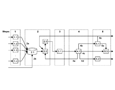
[0052] Figure 1 depicts a block flow diagram of the herein described
process. The
steps are denoted by blocks with dashed lines and are numbered from 1 to 5.
Within each of
the dashed line blocks the next level of process detail is provided. Each
major unit is
numbered. Only streams were differentiation is needed to clarity are numbered.
[0053] Figure 2 depicts a detailed block flow diagram of the third
step and the fourth
step of Figure 1, with major streams identified.
[0054] Figure 3 depicts oligomerization unit, unit 5.1 in Figure 1, in
more detail with
major streams identified.
[0055] Figure 4 depicts an expansion of Figure 3 showing how the lightest
product
fraction from the oligomerization unit, which includes synthesis gas
compounds, is further
processed.
[0056] Figure 5 depicts an expansion of Figure 3 showing how yield of
synthetic jet
fuel can be increased.
[0057] Figure 6 depicts hydrocracking unit, unit 5.2 in Figure 1, in more
detail with
major streams identified where the hydrogen feed and hydrogen recycle is not
shown.
[0058] Figure 7 depicts hydrotreating unit, unit 5.3 in Figure 1, in
more detail with major
streams identified, where the hydrogen feed and hydrogen recycle is not shown.
[0059] Figure 8 depicts an expansion of Figure 7 showing how the
product from the
.. hydrotreater is separated.
[0060] Figure 9 depicts an example of a system for producing synthetic
synthesis gas,
where A depicts a hydrothermal liquefaction unit; B depicts a supercritical
water gasification
unit; C depicts a reformation unit; and X-X' indicates feed-flow between A and
B, and Z-Z'
indicates feed-flow between B and C.
- 7 -
CA 03127385 2021-07-21
WO 2020/154810 PCT/CA2020/050111
DETAILED DESCRIPTION
[0061] Generally, the present disclosure provides a process for
producing synthetic jet
fuel, comprising converting feedstock to synthesis gas; converting the
synthesis gas into a
mixture comprising liquid hydrocarbons; refining the mixture comprising liquid
hydrocarbons to
isolate a kerosene product; and hydrotreating the kerosene product to form
synthetic jet fuel.
[0062] In an example of the present disclosure, there is provided a
process wherein
converting feedstock to synthesis gas comprises: pyrolyzing the feedstock
under aqueous
conditions to form a mixture comprising biocrude.
[0063] In another example, there is provided a process wherein the
feedstock
comprises biomass, organic materials, waste streams, or a combination thereof
with a high
water content.
[0064] In another example, there is provided a process wherein
converting feedstock
to synthesis gas comprises: pyrolyzing the feedstock to form a mixture
comprising biocrude.
[0065] In another example, there is provided a process wherein the
feedstock
comprises biomass, organic materials, waste streams, or a combination thereof
with a low
water content.
[0066] In another example, there is provided a process wherein
converting feedstock
to synthesis gas further comprises: gasifying the mixture comprising biocrude
to form the
synthesis gas.
[0067] In another example, there is provided a process wherein gasifying
the mixture
comprising biocrude comprises: supercritical water gasification of the mixture
comprising
biocrude to form a mixture comprising CH4, CO, 002, and H2; and reforming the
mixture
comprising CH4, CO, 002, and H2 to form the synthesis gas.
[0068] In another example, there is provided a process wherein
reforming comprises
dry reformation and steam reformation.
[0069] In another example, there is provided a process wherein when
converting
feedstock to synthesis gas, the process further comprises: adding an oil
feedstock, a sugar
feedstock, and/or an alcohol feedstock to the mixture comprising biocrude
before gasifying.
[0070] In another example, there is provided a process wherein the
synthesis gas
comprises a H2 to CO ratio that is less than 2 to 1.
[0071] In another example, there is provided a process wherein the
synthesis gas
comprises a stoichiometric ratio of (H2 - 002)/(00 + 002) that is less than 2
to 1.
- 8 -
CA 03127385 2021-07-21
WO 2020/154810 PCT/CA2020/050111
[0072] In another example, there is provided a process wherein the
synthesis gas
comprises a Ribblet ratio of (H2)/(200 + 3CO2), that is less than 1 to 1.
[0073] In another example, there is provided a process wherein
converting the
synthesis gas into a mixture comprising liquid hydrocarbons comprises:
performing a Fischer-
Tropsch synthesis to convert the synthesis gas into a mixture comprising
liquid hydrocarbons.
[0074] In another example, there is provided a process wherein the
Fischer-Tropsch
synthesis is performed with an iron-based catalyst.
[0075] In another example, there is provided a process wherein when
performing the
Fischer-Tropsch synthesis to convert the synthesis gas into a mixture
comprising liquid
hydrocarbons, the process further comprises: a water-gas shift reaction to
increase
concentration of H2.
[0076] In another example, there is provided a process wherein the
Fischer-Tropsch
synthesis is performed at a pressure of approximately 2 MPa; or at a pressure
of greater than
2 MPa; or approximately 2.5 MPa; or approximately 2.8 MPa.
[0077] In another example, there is provided a process wherein the Fischer-
Tropsch
synthesis is performed at a pressure in a range of about 1.5 MPa to 5 MPa; or
in a range of
about 2 MPa to about 4 MPa; or in a range of about 2 MPa to about 3 MPa; or in
a range of
about 1.5 to about 2.5 MPs; or in a range of about 2 MPa to about 2.5 MPa.
[0078] In another example, there is provided a process wherein the
Fischer-Tropsch
synthesis is performed at a pressure of greater than 2 MPa.
[0079] In another example, there is provided a process wherein the
mixture comprising
liquid hydrocarbons comprises an alkene to alkane ratio that is great than 1
to 1.
[0080] In another example, there is provided a process wherein
refining the mixture
comprising liquid hydrocarbons to isolate a kerosene product comprises:
performing a vapour-
liquid equilibrium separation on the mixture comprising liquid hydrocarbons;
and separating
the mixture into the kerosene product and at least one of an aqueous product,
a naphtha and
gas product, or a gas oil and heavier product.
[0081] In another example, there is provided a process wherein the
vapour-liquid
equilibrium separation is performed as a single-stage separation and/or a
multi-stage
separation.
[0082] In another example, there is provided a process wherein when an
aqueous
product is separated, refining the mixture comprising liquid hydrocarbons to
isolate a kerosene
product further comprises: adding the separated aqueous product to the mixture
comprising
- 9 -
CA 03127385 2021-07-21
WO 2020/154810 PCT/CA2020/050111
biocrude before gasifying the mixture comprising biocrude when converting
feedstock to
synthesis gas.
[0083] In another example, there is provided a process wherein, when a
naphtha and
gas product is separated, refining the mixture comprising liquid hydrocarbons
to isolate a
.. kerosene product further comprises: oligomerizing the naphtha and gas
product to form a
mixture comprising a first additional kerosene product.
[0084] In another example, there is provided a process wherein
oligomerizing the
naphtha and gas product is performed at a pressure of approximately 2.5 MPa;
or
approximately 2 MPa.
[0085] In another example, there is provided a process wherein
oligomerizing the
naphtha and gas product is performed at a pressure in a range of about 1.5 MPa
to 3 MPa; or
in a range of about 1.5 MPa to about 2.5 MPa; or in a range of about 2 MPa to
about 2.5 MPa.
[0086] In another example, there is provided a process wherein
oligomerizing the
naphtha and gas product is performed with a non-sulfided catalyst.
[0087] In another example, there is provided a process wherein
oligomerizing the
naphtha and gas product is performed with an acidic ZSM-5 zeolite catalyst.
[0088] In another example, there is provided a process wherein the
first additional
kerosene product comprises alkene and aromatic compounds.
[0089] In another example, there is provided a process wherein the
first additional
kerosene product comprises approximately 0% to approximately 60% aromatic
compounds;
approximately 1% to approximately 60% aromatic compounds; or approximately 1%
to
approximately 50% aromatic compounds; or approximately 1% to approximately 40%
aromatic
compounds; or approximately 1% to approximately 30% aromatic compounds; or
approximately 0% to approximately 1% aromatic compounds; or approximately 1%
to
.. approximately 7% aromatic compounds; or approximately 8% to approximately
25% aromatic
compounds; or approximately 8% aromatic compounds.
[0090] In another example, there is provided a process wherein, when a
gas oil and
heavier product is separated, refining the mixture comprising liquid
hydrocarbons to isolate a
kerosene product further comprises: hydrocracking the gas oil and heavier
product to form a
mixture comprising a second additional kerosene product.
[0091] In another example, there is provided a process wherein
hydrocracking the gas
oil and heavier product is performed at a pressure of approximately 2.5 MPa;
or approximately
2 MPa.
- 10-
CA 03127385 2021-07-21
WO 2020/154810 PCT/CA2020/050111
[0092] In another example, there is provided a process wherein
hydrocracking the gas
oil and heavier product is performed at a pressure in a range of about 1.5 MPa
to 3 MPa; or in
a range of about 1.5 MPa to about 2.5 MPa; or in a range of about 2 MPa to
about 2.5 MPa.
[0093] In another example, there is provided a process wherein
hydrocracking the gas
oil and heavier product is performed with a non-sulfided catalyst.
[0094] In another example, there is provided a process wherein the
hydrocracking is
performed with a noble metal catalyst supported on amorphous silica-alumina.
In another
example, the catalyst is Pt/SiO2-A1203.
[0095] In another example, there is provided a process wherein
hydrotreating the
kerosene product to form synthetic jet fuel comprises: hydrotreating the
kerosene product, and
when a naphtha and gas product is separated, hydrotreating the first
additional kerosene
product, to form a mixture comprising paraffinic hydrocarbons; and
fractionating the mixture
comprising paraffinic hydrocarbons, and when a gas oil and heavier product is
separated,
fractionating the mixture comprising the second additional kerosene product,
to isolate the
synthetic jet fuel.
[0096] In another example, there is provided a process wherein when
fractionating the
mixture comprising paraffinic hydrocarbons and fractionating the mixture
comprising the
second additional kerosene product, the process further comprises: adding the
mixture
comprising the second additional kerosene product to the mixture comprising
paraffinic
hydrocarbons before fractionating.
[0097] In another example, there is provided a process wherein each of
the kerosene
product, the first additional kerosene product, and the second additional
kerosene product
have a normal boiling point temperature range of about 140 C to about 300 C.
[0098] In another example, there is provided a process wherein the
hydrotreating is
performed at a pressure of approximately 2.5 MPa; or approximately 2 MPa.
[0099] In another example, there is provided a process wherein the
hydrotreating is
performed at a pressure in a range of about 1.5 MPa to 3 MPa; or in a range of
about 1.5 MPa
to about 2.5 MPa; or in a range of about 2 MPa to about 2.5 MPa.
[00100] In another example, there is provided a process wherein the
hydrotreating is
performed with a non-sulfided catalyst.
[00101] In another example, there is provided a process wherein the
hydrotreating is
performed with a reduced base metal catalyst supported on alumina or silica.
In another
example, the catalyst is reduced Ni/A1203.
-11-
CA 03127385 2021-07-21
WO 2020/154810 PCT/CA2020/050111
[00102] In another example, there is provided a process wherein the
synthetic jet fuel is
a semi-synthetic jet fuel, a fully synthetic jet fuel, or a combination
thereof.
[00103] Before explaining the present invention in detail, it is to be
understood that the
invention is not limited to the exemplary embodiments contained in the present
application.
.. The invention is capable of other embodiments and of being practiced or
carried out in a variety
of ways. It is to be understood that the phraseology and terminology employed
herein are for
the purpose of description and not of limitation.
[00104] It will be appreciated that for simplicity and clarity of
illustration, where
considered appropriate, reference numerals may be repeated among the figures
to indicate
corresponding or analogous elements or steps. In addition, numerous specific
details are set
forth in order to provide a thorough understanding of the exemplary
embodiments described
herein. However, it will be understood by those of ordinary skill in the art
that the embodiments
described herein may be practiced without these specific details. In other
instances, well-
known methods, procedures and components have not been described in detail so
as not to
obscure the embodiments described herein. Furthermore, this description is not
to be
considered as limiting the scope of the embodiments described herein in any
way, but rather
as merely describing an exemplary implementation of the various embodiments
described
herein.
[00105] Unless defined otherwise, all technical and scientific terms
used herein have
the same meaning as commonly understood by one of ordinary skill in the art to
which this
invention belongs.
[00106] As used in the specification and claims, the singular forms
"a", "an" and "the"
include plural references unless the context clearly dictates otherwise.
[00107] The term "comprising" as used herein will be understood to mean
that the list
following is non-exhaustive and may or may not include any other additional
suitable items, for
example one or more further feature(s), component(s) and/or ingredient(s) as
appropriate.
[00108] As used herein, the terms "about" and "approximately" are used
in conjunction
with ranges of dimensions, concentrations, temperatures, or other physical or
chemical
properties and characteristics. Use of these terms is meant to cover slight
variations that may
exist in the upper and lower limits of the values or ranges of properties and
characteristics, for
example by 10%, or 5%.
[00109] As used herein, 'aviation turbine fuel' or 'jet fuel' refers to
kerosene before
addition of required fuel additives to meet specification requirements for
synthetic aviation
- 12 -
CA 03127385 2021-07-21
WO 2020/154810 PCT/CA2020/050111
turbine fuel as either a jet fuel blend component with petroleum derived
kerosene (i.e. semi-
synthetic jet fuel), or a jet fuel without any petroleum derived kerosene
(i.e. fully synthetic jet
fuel). For example, these specification requirements are described in
appropriate standards
documents, such as the United Kingdom Ministry of Defense. Defense Standard 91-
91, Issue
.. 7. Turbine Fuel, Kerosine Type, Jet A-1, NATO Code: F-35, Joint Service
Designation: AVTUR;
Ministry of Defence: London, 18 February 2011, and ASTM D 7566-15b updated to
ASTM D
7566-19 (e.g., see Annex Al, synthesized paraffinic kerosene (SPK) with
aromatics).
Standard specification for aviation turbine fuel containing synthesized
hydrocarbons; American
Society for Testing and Materials: West Conshohocken, PA, 2015. As a skilled
person would
recognize, only a few of the specification requirements may to be met by
adding additives;
many of the specification requirements may be met via the refining process
(e.g., see Example
4 below, wherein it was possible to meet requirements after adding only a
static dissipator).
[00110] As used herein, 'feedstock' refers to biomass, organic
materials, waste streams,
or combinations thereof. Examples of feedstocks includes but is not limited to
a waste stream
from a grain ethanol plant (bagasse, stillage, wastewater and glycerin),
cellulosic biomass
(wood, energy crops, grasses), organic wastes (green bin collection waste
products; sewage
sludge), agricultural wastes (agricultural plant wastes or residues, manure),
pulp and paper
plant waste streams (wood waste, prehydrolysate), municipal-sorted organic
wastes, biodiesel
(glycerin) and any combinations thereof. Examples of biomass include, but are
not limited to
materials that are by-products from activities such as forest harvesting,
products
manufacturing, construction, and demolition debris harvesting or management;
and
lignocellulosic biomass, for example wood based residues, which are classified
into three
categories: forest residues, urban residues, and mill residues. Examples of
organic materials
include, but are not limited to any one of cellulosic materials,
lignocellulosic materials, wastes,
such as wood processing wastes, agricultural residues, municipal green bin
collections,
manures, an effluent from a cellulosic material processing plant, an effluent
from a paper plant,
an effluent from an ethanol-from-biomass process, thin or whole stillage, dry
distillers grains,
and biodegradable waste waters; materials with carbon and hydrogen in its
molecular
structure, for example alcohols, ketones, aldehydes, fatty acids, esters,
carboxylic acids,
ethers, carbohydrates, proteins, lipids, polysaccharides, monosaccharide,
cellulose, nucleic
acids, etc.; and may be present for example, in waste (e.g. agricultural or
industrial waste
streams; sewage sludge), organic fluid streams, fresh biomass, pretreated
biomass, partially
digested biomass, etc. In some examples, 'feedstock' as defined herein
includes feedstocks
- 13-
CA 03127385 2021-07-21
WO 2020/154810 PCT/CA2020/050111
with a high water content and/or feedstocks with a low energy density. In some
examples,
'feedstock' as defined herein includes feedstocks with a low water content.
[00111] In some examples, a high water content refers to a material
having water
present as a separate phase at ambient conditions. In an example, a high water
content refers
to a material with a water content that exceeds the organic matter content. In
other examples,
a high water content refers to a water content of, for example, >40 wt%, or,
between about 50
wt% to about 95 wt%; or between about 60 wt% to about 90 wt%; or between about
70 wt% to
about 90 wt%; or between about 80 wt% to about 90 wt%; or, any value between
about 50
wt% and about 70 wt% to any value between about 75wt% and about 95 wt%. In
some
examples, a low water content refers to a material without water present as a
separate phase
at ambient conditions. In other examples, a low water content refers to a
water content of, for
example, wt%, or, between about 5 wt% to about 40 wt%; or between about
10 wt% to
about 40 wt%; or between about 20 wt% to about 40 wt%; or between about 30 wt%
to about
40 wt%; or, any value between about 5 wt% and about 20 wt% to any value
between about
25wt% and about 40 wt%.
[00112] As used herein, 'oil feedstock' refers to vegetable oils or
animal fat oils. In some
examples, 'oil feedstock' refers to waste vegetable oils or animal fat oils.
'Sugar feedstock'
refers to solutions of sugar. In some examples, the sugar may be waste sugar.
'Alcohol
feedstock' refers to liquid alcohols such as glycerol. In some examples, the
liquid alcohol may
be a waste alcohol.
[00113] As used herein, `pyrolyzing feedstock under aqueous conditions'
refers to
pyrolysis or thermal treatment of feedstock in the presence of water present
as a separate
phase at ambient conditions; as such, but not limited to, hydrothermal
liquefaction. As used
herein, rpyrolyzing feedstock' refers to pyrolysis or thermal treatment of
feedstock where water
is not present as a separate phase at ambient conditions;. As would be
recognized by a person
of skill in the art, 'aqueous conditions' refer to water being present at an
amount sufficient to
act as, e.g., a reagent, catalyst, solvent, or combination thereof. As a
skilled person would also
recognize, rpyrolyzing conditions' may refer to the absence of water; or to
water being present
at an amount that would not be sufficient for acting as, e.g., a reagent,
catalyst, solvent, or
combination thereof.
[00114] As used herein, 'liquid hydrocarbons' refers to linear,
branched, and/or cyclic
alkanes and alkenes (olefins), or aromatic compounds that may be unsubstituted
or substituted
- 14 -
CA 03127385 2021-07-21
WO 2020/154810 PCT/CA2020/050111
with oxygen-containing functional groups, such as but not limited to alcohols,
aldehydes,
carboxylic acids, ketones, ethers, etc.
[00115] As used herein, 'biocrude' is a mixture that includes but is
not limited to aromatic
cornpounds, polyaromatic compounds, fatty acids, alkanes, alkenes, and/or
oxygen-containing
compounds.
[00116] As used herein, 'paraffinic hydrocarbons' refers to linear or
branched alkanes,
and may include cycloalkanes.
[00117] Described herein is a process that converts feedstocks, such as
biomass, waste
feedstocks, oil feedstocks, sugar feedstocks, and/or alcohol feedstock to a
synthetic jet fuel
that is suitable for blending, or for direct use as a semi-synthetic or fully
synthetic jet fuel.
[00118] With reference to Figure 1, an example of the process is
described in five steps,
as indicated by blocks with dashed lines. The five steps include (1) pyrolysis
of feedstock, or
pyrolysis of feedstock under aqueous conditions (e.g., hydrothermal
liquefaction) to produce a
mixture comprising bio-crude, (2) gasification of the mixture comprising
biocrude to form
synthesis gas, and optionally adding an oil feedstock, a sugar feedstock,
and/or an alcohol
feedstock to the mixture comprising biocrude before gasifying, (3) performing
a Fischer¨
Tropsch synthesis to convert the synthesis gas into a mixture comprising
liquid hydrocarbons,
(4) refining the mixture comprising liquid hydrocarbons to isolate a kerosene
product, and least
three other fractions, and (5) hydrotreating the kerosene product to produce
jet fuel as a major
product. In some examples, step 1 of Figure 1 is performed at distributed
locations and steps
2 to 5 of Figure 1 are performed in a central location.
[00119] Step 1 of Figure 1 is directed towards converting feedstock,
such as bulky low
energy-density feedstocks, into a denser liquid that can be readily handled
and transported. In
an example of step 1, pyrolysis under aqueous conditions involves hydrothermal
liquefaction,
as depicted by block 1 in Figure 1. As depicted, the hydrothermal liquefaction
units are small-
scale distributed units that can be deployed close to a feedstock source, such
as a source of
biomass or waste materials. The hydrothermal liquefaction units are
represented by blocks 1.1
to 1.n in Figure 1, where n is a positive integer value. By deploying direct
liquefaction units in
a distributed fashion, the distance from the raw feedstock to a central plant
is reduced; and,
since the product produced in step 1 (i.e., a mixture comprising biocrude) has
a lower water
content and higher physical density and energy density than the feedstock,
this conversion
can make transport to a large centralized final product factory viable. By
producing a mixture
comprising biocrude, which is a liquid product, it is relatively easier to
homogenize than
- 15-
CA 03127385 2021-07-21
WO 2020/154810 PCT/CA2020/050111
densified solid products. Optionally, one of the hydrothermal liquefaction
units may be located
at the central processing facility. In another example of step 1, not shown,
other liquefaction
technologies may be selected, as appropriate, for each of the distributed
feedstocks, such as
pyrolysis to produce oil from dry/solid-like feedstocks. In said example, the
blocks 1.n of step
.. 1 are pyrolysis units. When only a single localized feed source is
available, then n = 1 in Figure
1 and only a single hydrothermal liquefaction unit is employed.
[00120] Hydrothermal liquefaction is a process whereby a feedstock is
heated under
aqueous conditions for a time period sufficient to substantially hydrolyze the
feedstock and
produce a liquefaction product that has lower average molecular mass than the
feed.
.. Hydrothermal liquefaction is an example of a direct liquefaction process.
The hydrothermal
liquefaction process may be implemented as a batch, semi-batch, or continuous
process under
subcritical or supercritical water conditions. The operating conditions,
supercritical or
subcritical, also dictate a minimization of char formation and oxygen contents
in the liquefaction
product. Some non-condensable gases produced during this process may be used
as fuel
.. gases to provide required energy. Hydrothermal liquefaction does not
require the feedstock
to be dried. Depending on the temperature to which the feedstock is heated,
pressure will
autogenously develop to limit vaporization of water. Subsequent to
hydrothermal liquefaction,
a liquid-liquid phase separation may be employed to separate water and
liquefaction product.
The hydrothermal liquefaction process can be implemented at small-scale to the
extent that it
.. can be implemented even on a mobile unit.
[00121] In an example of the process as described herein, hydrothermal
liquefaction
(HTL) is conducted at a temperature of about 350 C for 40 minutes.
Alternatively, it is
conducted in supercritical water around 410 C for only a few minutes (e.g.,
about 5 minutes
or less). As a skilled person would recognize, different hydrothermal
liquefaction conditions
can create slight different biocrudes, a main difference being the amount of
oxygen in the
biocrudes: supercritical water HTL can produce biocrudes containing from about
8% to about
10% oxygen, while HTL pyrolysis can produce biocrudes containing oxygen in the
low 40%
range. The process as described herein can accept all different types of
biocrudes/bio oils.
[00122] In one example, trailers with mobile liquefaction units (e.g.,
hydrothermal
liquefaction units, or pyrolysis units, etc.) may be parked on farms to
process farm waste and
biomass to a liquefaction product (e.g., a mixture comprising biocrude) that
is collected in a
mobile tank for intermittent collection. Such mobile units would typically be
designed for simple
and unsupervised operation. In another example, larger stationary liquefaction
units may be
- 16 -
CA 03127385 2021-07-21
WO 2020/154810 PCT/CA2020/050111
stationed at facilities, such as municipal waste handling facilities and saw
or paper mills, where
a collection network for biomass and waste feedstocks is already in place.
These stationary
liquefaction units would typically be designed with more complex heat
integration for higher
efficiency of operation due to their larger scale. The rest of the process is
conducted at a central
facility, where the liquefaction product (e.g., a mixture comprising biocrude)
is collected from
the distributed liquefaction units and processed.
[00123] Step 2 of Figure 1 is directed towards combining and
homogenizing the
liquefaction product (i.e., the mixture comprising biocrude) (see unit 2.1 in
Figure 1) from step
1 (see 2a in Figure 1) , and potentially an oil feedstock, a sugar feedstock,
and/or an alcohol
feedstock from other sources than step 1, such as waste vegetable or animal
fat oils (see 2b
in Figure 1), and then to gasify these feed materials to raw synthesis gas
(see unit 2.2 in Figure
1). As indicated in Figure 1, the feed materials for the production of raw
synthesis gas (in unit
2.2) may additionally include a Fischer¨Tropsch aqueous product (stream 4a)
and material
from refining (stream 5b). The raw synthesis gas is then cleaned (see unit 2.3
in Figure 1) to
produce clean synthesis gas.
[00124] The term raw synthesis gas refers to a gas that includes a
mixture of hydrogen
(H2) and carbon monoxide (CO), along with other compounds. The other compounds
typically
include, but are not limited to carbon dioxide (CO2), water vapor (H20), and
methane (CH4).
The term clean synthesis gas refers to raw synthesis gas after removal of
potentially
detrimental compounds that were present in the raw synthesis gas. The most
common class
of contaminants that must be removed is sulfur-containing compounds such as
hydrogen
sulfide (H2S) and carbonyl sulfide (COS). Additionally other compounds may
also be removed
during cleaning to improve efficiency of downstream processes.
[00125] Employing a mixture comprising biocrude as a feed for raw
synthesis gas
production, as well as other liquid feeds, such as oil feedstocks, sugar
feedstocks, and/or
alcohol feedstocks, can reduce the impact of feed heterogeniety by blending in
a feed tank
(see unit 2.1 in Figure 1) prior to gasification. Since the feed material is
largely liquid, it is easier
to homogenize feed materials from different sources. Further, a liquid feed
can make producing
a raw synthesis gas production relatively simpler and efficient, because it
avoids solids
handling; liquid feeds can be pumped to pressurize them; liquid feeds can have
superior heat
transfer properties for gasification; and when washed, it is void of minerals
that can potentially
contaminate the synthesis gas. Operating pressure of the raw synthesis gas
generation step
affects the downstream operation. It is of benefit to perform raw synthesis
gas generation at
- 17-
CA 03127385 2021-07-21
WO 2020/154810 PCT/CA2020/050111
an elevated pressure. In an example, raw synthesis gas is generated at
pressure of about 2
MPa or higher; or in a range of about 2 MPa to 5 MPa; or in a range of about 2
MPa to about
4 MPa; or in a range of about 2 MPa to about 3 MPa.
[00126] In an example of the process as described herein, the raw
synthesis gas is
produced by supercritical water gasification (SCWG). With SCWG and the
appropriate amount
of water with respect to the carbon/hydrogen/oxygen content, heat required for
the gasification
is generated within a reactor by the SCWG exothermic reactions once the
gasification has
been started by an external heat source, such as a start-up furnace. As such,
SCWG does not
require a constant source of external heat, while excess water requires some
external heat.
Further, the SCWG reactor operates at a lower temperature, and without a need
to employ an
externally supplied oxidant. Water in the SCWG reactor gives up some of its
hydrogen, typically
through the water-gas shift reaction, to increase the hydrogen-to-carbon ratio
in the raw
synthesis gas above that generally anticipated from gasification of the liquid
feeds alone. All
feed materials are introduced into the SCWG process in the liquid phase at
high pressure,
generally above pressure requirements of a synthesis gas feed for a
Fischer¨Tropsch
synthesis, which is both energy efficient, and less complex than compressing
the raw synthesis
gas after being produced. Hot gas coming out of the SCWG reactor exchanges
heat with
incoming feedstock, and water vapors in the gas are cooled/condensed along
with other water
soluble organic compounds, and separated in pressurized liquid/gas separators.
Part of the
separated water-rich product is recycled back into the SCWG process. At this
point, the raw
synthesis gas may still contain compounds other than hydrogen and carbon
monoxide. Some
of these compounds may be removed by condensation, but some gas cleaning (see
unit 2.3
in Figure 1) may be required to remove gaseous contaminants that could affect
downstream
processes. Cleaned synthesis gas may still contain compounds other than
hydrogen and
carbon monoxide, such as water vapor and carbon dioxide, but it would be
substantially free
from sulfur-containing compounds. Methods for cleaning the raw synthesis gas
to obtain clean
synthesis gas are known to persons skilled in the art.
[00127] In an example of the process as described herein, supercritical
water
gasification (SCWG) is conducted at a temperature in the range of 570 C to 590
C, with a
water content of about 30% to about 60%, and at a pressure in the range of
about 20 MPa to
about 30 MPa, or about 22.5 MPa to about 25 MPa. In another example,
supercritical water
gasification (SCWG) is conducted at a temperature of about >550 C, with the
pressure being
dependent on reactor design and means for pressure control.
- 18-
CA 03127385 2021-07-21
WO 2020/154810 PCT/CA2020/050111
[00128] In some examples of step 2, reforming is used in conjunction
with clean
synthesis gas production to convert hydrocarbons present in the clean
synthesis gas to
hydrogen and carbon monoxide. Presence of enough methane in raw synthesis gas,
along
with carbon dioxide, allow reformation of these gases using steam reforming
and dry reforming.
This also allows for recycling of additional CO2 from the raw synthesis gas to
maximize
conversion of the methane into carbon monoxide and hydrogen. Some carbon
dioxide and
water is also produced in the formation processes. Water may be separated by
cooling the
gases, and carbon dioxide may be reduced in a synthesis gas clean up unit.
[00129] In its simplest form, the reactions of steam reforming and dry
methane
reforming, along with the water-gas shift and reverse water-gas shift
reactions during step 2
are as follows:
1. CH4 + CO2 # 2C0 +2 H2
2. CH4 +2 H20 # CO + 3H2
3. 002 + H2 CO + H20
4. CO + H20 # CO2 + H2
[00130] Optionally, the use of a water-gas shift converter may be
considered to change
the molar ratio of hydrogen-to-carbon monoxide in the clean synthesis gas. At
least some of
the potential technologies that could be selected for step 3 may benefit from
a hydrogen to
carbon monoxide molar ratio that is closer to 2 to 1. Optionally, production
of clean synthesis
gas is followed by removal of some CO2 from the clean synthesis gas. Part of
the CO2 could
be recycled.
[00131] Figure 9 depicts an example of a system for producing synthesis
gas that can
be used with the process as described herein, where A depicts a hydrothermal
liquefaction
unit; B depicts a supercritical water gasification unit; and C depicts a
reformation unit.
[00132] More particularly, Figure 9A depicts an example of a
hydrothermal liquefaction
(HTL) unit that involves:
= Feedstock of all types, such as all types of organic wastes, manures,
sewages sludge,
agricultural and forest residues, and all biomass types;
= Feedstock ratio adjustment to suit 20% dry matter, with possible water
adjustment;
= Feedstock (20% dry matter) pumped via high pressure feed pump to a heat
recovery
unit, and then pumped to a heater unit;
- 19-
CA 03127385 2021-07-21
WO 2020/154810 PCT/CA2020/050111
= Feed, which may include an organic/aqueous phase from a Fischer-Tropsch
unit, is
then pumped from the heater unit to a HTL reactor via an HP pump, and then
back to
the heater unit;
= From the heater unit following the HTL reactor, the feed is moved to a
cooler and then
to a product separator;
= The product separator outputs non-condensable gases and biocrude oil
(which is then
pumped to the supercritical water gasification unit of Figure 9B); and
= The product separator also outputs to an HTL water collection that
outputs a salt purge,
and water recycled after salt separation that goes to the high pressure feed
pump.
[00133] Figure 9B depicts an example of a supercritical water (SOW)
biocrude
gasification unit that involves:
= Receiving the biocrude oil from the HTL unit of Figure 9A, which is moved
to a heat
recovery unit, and then a heater;
= From the heater, the feed is moved to a SCWG reactor (which has an output
to energy
sink 'ET
= Feed output from the reactor is moved back to the heat recovery unit, and
then to a
pressure reducing turbine (which also outputs to energy sink 'ET
= From the turbine, the feed is moved to another heat recovery unit, then
to a cooler;
= From the cooler, the feed is moved to an high-pressure gas/liquid
separator (an HP
flash) that outputs an aqueous phase and a biogas (which is then moved to the
reforming unit of Figure 9C); and
= The aqueous phase is made part of a water recycle, that accepts make-up
water and
then is fed back to the second heat recovery unit (which feeds heat to the
heater).
[00134] Figure 9C depicts an example of a reforming unit that involves:
= Receiving the biogas from the SCWG unit of Figure 9B, which is moved to a
heat
recovery unit, and then to an HRSG;
o A heat recovery steam generator (HRSG) inputs also include make-up water
(pumped to the HRSG via an HRSG feed water pump);
o An HRSG output includes a surplus stream to energy sink `E;
o The heat recovery unit and HRSG both also feed a steam methane/dry methane
reformation unit (SMR/DMR), an output of which is fed back to the heat
recovery
unit;
- 20 -
CA 03127385 2021-07-21
WO 2020/154810 PCT/CA2020/050111
= From the HRSG, the feed is moved to a cooler, and then to an HP flash;
= Another HP flash input includes recycle water from make-up water; and
= From the HP flash, the feed is moved to a CO2 clean-up unit that outputs
syngas that
may be directed to a Fischer-Tropsch unit, and CO2 (including recycle CO2 that
is fed
back to the heat recovery unit, and surplus CO2).
[00135]
Step 3 of Figure 1 is directed towards conversion of synthesis gas to a
mixture
comprising liquid hydrocarbons via a Fischer-Tropsch synthesis (see unit 3.1
in Figure 1).
Methanol synthesis is an alternative process that can be employed for this
step, but conversion
of methanol to hydrocarbons is known to produce 1,2,4,5-tetramethylbenzene, a
highly
undesirable kerosene range product when producing jet fuel.
[00136] In
its simplest form, the main reactions during step 3 for Fischer¨Tropsch
synthesis can be represented by the following Equations 1-6, where Equation 6
is relevant only
in iron-catalyzed Fischer¨Tropsch synthesis:
Alkenes: n CO + 2n H2 ¨> (CH2),, + n H20 (1)
Alkanes: n CO + (2n+1) H2 ¨> H(CH2)õH + n H20 (2)
Alcohols: n CO + 2n H2 ¨> H(CH2)n0H + (n-1) H20 (3)
Carbonyls: n CO + (2n-1) H2 ¨> (CH2)0 + (n-1) H20 (4)
Carboxylic acids: n CO + (2n-2) H2 ¨> (CH2)n02 + (n-2) H20 (5)
Water gas shift: CO + H2O # CO2 + H2 (6)
[00137] The
value of n in Equations 1 to 6 depends on the probability of chain growth.
The probability of chain growth, or alpha-value, depends on the nature and
operation of the
Fischer¨Tropsch catalyst. The product distribution is reasonably well
represented by an
Anderson-Schulz-Flory distribution. With the Fischer¨Tropsch synthesis of the
herein
described process, products from the Fischer¨Tropsch synthesis will typically
have carbon
numbers in the range of n =1 to 100, although some products with n> 100 may
form.
[00138] In
an example of step 3, iron-catalyzed Fischer¨Tropsch synthesis is employed
for conversion of synthesis gas to product mixture comprising liquid
hydrocarbons. Iron-
catalyzed Fischer¨Tropsch syntheses does not require the synthesis gas
composition to be
adjusted to meet the hydrogen-to-carbon monoxide usage ratio of approximately
2 to 1,
because iron-based Fischer¨Tropsch catalysts are capable of performing the
water-gas shift
reaction. In an example, iron-catalyzed Fischer¨Tropsch synthesis is performed
at a
temperature of 240 C and higher, or at a temperature in a range 240 to 280
C. Operating the
Fischer¨Tropsch synthesis at a higher temperature allows the exothermic heat
of reaction to
- 21 -
CA 03127385 2021-07-21
WO 2020/154810 PCT/CA2020/050111
be removed by high-pressure steam production, typically to generate steam at a
pressure of 4
M Pa or higher.
[00139] In another example of step 3, the iron-based Fischer¨Tropsch
synthesis is
performed with a synthesis gas that has a hydrogen-to-carbon monoxide ratio
less than 2 to
1. In another example, the iron-based Fischer¨Tropsch synthesis is performed
with a synthesis
gas that has a stoichiometric ratio, (H2 - 002)/(CO + 002), of less than 2 to
1. In another
example, the iron-based Fischer¨Tropsch synthesis is performed with a
synthesis gas that has
a Ribblet ratio, (H2)/(2 CO + 3 002), of less than 1 to 1. In another example,
the design of the
Fischer¨Tropsch synthesis is such that the mixture comprising liquid
hydrocarbons from the
Fischer¨Tropsch synthesis has an alkene to alkane ratio that is greater than 1
to 1. Said alkene
to alkane ratio being greater than 1 to 1 is generally desired for the process
as described herein
given that, as the alkene:alkane ratio decreases, oligomerization can be
affected (e.g. the
oligomerization yield can be decreased), which can reduce the ability to
produce fully synthetic
jet.
[00140] In another example, the design of the Fischer¨Tropsch synthesis is
such that
the once-through carbon monoxide conversion of synthesis gas during
Fischer¨Tropsch
synthesis is high, typically higher than 80% and more preferably higher than
90%. In another
example, the design of the Fischer¨Tropsch synthesis is such that steam is fed
to the Fischer¨
Tropsch synthesis as necessary for the reaction to proceed without excessive
carbon
formation.
[00141] Following is a more detailed description of an example of step
3 of Figure 1 (see
Figure 2). In step 3, the synthesis gas that is represented by stream 299 in
Figure 2, is
converted by Fischer¨Tropsch synthesis represented by block 300, into a
mixture comprising
liquid hydrocarbons represented by streams 301 and 302. Step 3 is conducted at
temperature
and pressure conditions where it is likely that the Fischer¨Tropsch reactor
will have a gas
phase and a liquid phase present with the catalyst in the solid phase. The
reaction products
from the Fischer¨Tropsch synthesis (i.e., a mixture comprising liquid
hydrocarbons) could
leave the reactor as two separate phases, with the reactor itself serving as
both reactor and
phase separator. In Figure 2, stream 301 is the gas phase product and stream
302 is the liquid
phase product leaving the Fischer¨Tropsch reactor, block 300. The exact nature
and position
of the gas phase product and liquid phase product exiting the reactor depends
on the specific
reactor technology that is selected, such as a multitubular fixed bed reactor,
or a slurry phase
bubble column reactor. Any device needed to retain the catalyst in block 300,
is considered
- 22 -
CA 03127385 2021-07-21
WO 2020/154810 PCT/CA2020/050111
part of the technology in that block. Depending on the operation of the
Fischer¨Tropsch
synthesis, the relative amount of products in streams 301 and 302 could vary.
In an example,
no material leaves block 300 as stream 302. Due to the exothermic nature of
the reaction in
block 300 in Figure 2, water is supplied as stream 303 and vaporized to
produce steam as
stream 304. The water supplied in stream 303 does not mix with the process and
both streams
303 and 304 can be considered utility streams separate from the process, but
that are integral
to heat removal from block 300.
[00142] Step 4 of Figure 1 is directed towards separating the product
from Fischer¨
Tropsch synthesis (i.e., the mixture comprising liquid hydrocarbons) by
separating the mixture
into at least four product fractions (see unit 4.1 in Figure 1): (4a) aqueous
product, (4b) a
naphtha and gas product, (4c) a kerosene product, and (4d) a gas oil and
heavier product. The
aqueous product comprises water and water-soluble molecules that are condensed
during
product separation. The naphtha and gas product comprises all of the material
not present in
the aqueous product that has a normal boiling point temperature that is lower
than that of
kerosene. The kerosene product comprises hydrocarbons with a boiling range
that is
compatible with distillation requirements for jet fuel; broadly speaking, the
kerosene product
has a normal boiling point temperature range of 140 to 300 C. The gas oil and
heavier product
comprises material with a normal boiling point temperature higher than that of
kerosene. In
some examples, the four products are not isolated as precise cuts. In some
examples, vapor-
liquid equilibria would naturally result in some separation in the reactor for
Fischer¨Tropsch
synthesis. Part or all of the gas oil and heavier product (see stream 4d in
Figure 1) could be
available as a separate liquid product from Fischer¨Tropsch synthesis see
(unit 3.1 in Figure
1) and not require separation in the fourth step. To separate the heavier and
lighter products
of the Fischer¨Tropsch synthesis for conveniently upgrading to jet fuel, a
combination of vapor-
.. liquid equilibrium separation techniques at different pressure and
temperatures is used, and
may be combined with distillation of selected separated fractions. This avoids
necessity of an
atmospheric distillation unit in this part of the process, which can make step
4 relatively more
energy efficient and less capital intensive.
[00143] Following is a more detailed description of an example of step
4 of Figure 1 (see
Figure 2). The temperature of the gas phase product in stream 301 in Figure 2
is decreased
in block 400. It is possible to effect this change in temperature by devices
known in the art. In
an example, the temperature of stream 301 is decreased by heat exchange with
stream 299
in a feed-product heat exchanger represented by block 400. The temperature
change in block
- 23 -
CA 03127385 2021-07-21
WO 2020/154810 PCT/CA2020/050111
400 can also be effected in other ways, such as with a utility stream, or by
cooling with air. In
another example, the temperature of stream 401 is such that the water present
in stream 301
condensed and that the water in stream 401 is at its bubble point, or below
its bubble point.
The relationship between the bubble point temperature of the water in stream
401 and the
pressure is determined by vapor-liquid equilibrium. In another example, the
temperature of 401
is controlled and held constant by means of process control. Furthermore, this
temperature is
selected by optimizing product routing to step 5, instead of being used to
condense more
material, as is generally industrial practice. Therefore, this temperature is
controlled to be at,
or near the bubble point of water in stream 401. Stream 401 enters a phase
separator,
represented by block 410 in Figure 2. In this example, the phase separator is
a three-phase
phase separator. The purpose of the phase separator is to enable separation of
the phases
present in stream 401 to produce a gas phase stream 411, organic liquid phase
stream 412
and an aqueous liquid phase stream 413. In one example, block 400 and 410 are
combined in
one device that enables both temperature change and phase separation in the
same device.
In another example, block 400 and 410 are combined in such a way that the
device has more
than one equilibrium stage to effect separation into streams 411, 412, and
413.
[00144] The relationship between the streams shown in Figures 1 and 2
are indicated
on Figure 2. The gas phase stream 411 comprises mainly gaseous and naphtha
fraction
products, stream (4b). The organic liquid phase stream 412, comprises mainly
the kerosene
product, stream (4c). The aqueous product stream 413, comprises mainly water
with dissolved
organic compounds that are mainly oxygen-containing compounds, stream (4a).
The liquid
product from the Fischer¨Tropsch reactor is stream 302 and comprises of mainly
gas oil and
heavier organic compounds, stream (4d). The design and control of the herein
described
separation enables product routing in such a way that it is not necessary to
make use of a
separate atmospheric distillation unit prior to any of the units in step 5.
This exploits the energy
already available in the hot products from unit 300, without undermining
refinery operation.
[00145] Step 5 of Figure 1 is directed towards refining the four
product fractions
separated from the Fischer¨Tropsch liquefaction product (i.e., the mixture
comprising liquid
hydrocarbons). Refining employs three processes, namely, oligomerization (see
unit 5.1 in
Figure 1), hydrocracking (see unit 5.2 in Figure 1) , and hydrotreating (see
unit 5.3 in Figure 1) .
The aqueous product (see 4a in Figure 1) is recycled to be a feed in synthesis
gas production
(see unit 2.2 in Figure 1) . The aqueous product, like the hydrothermal
liquefaction product, is
acidic in nature. The combination of hydrothermal liquefaction product and
Fischer¨Tropsch
- 24 -
CA 03127385 2021-07-21
WO 2020/154810 PCT/CA2020/050111
aqueous product exploits the common need for acid resistant construction
material. Co-
feeding the aqueous product with the hydrothermal liquefaction product (i.e.,
the mixture
comprising biocrude) enables substantial conversion of the acids to synthesis
gas, instead of
relying on chemical dosing. It eliminates treating the aqueous product
separately as an acidic
wastewater with a high chemical oxygen demand, a costly necessity often
encountered in
industrial Fischer¨Tropsch based coal-to-liquid and gas-to-liquid facilities.
[00146] The
straight run gas and naphtha product (4b in Figure 1) is not further
separated, as is common practice in separation after Fischer¨Tropsch
synthesis. The gas and
naphtha product, which also contains unreacted synthesis gas, is directly used
as a feed
material for an oligomerization process. The oligomerization process refers to
a conversion
process that involves an addition reaction of two or more unsaturated
molecules. Such an
approach facilitates conversion of lighter olefinic (i.e., alkenyl) products
to heavier olefinic
products, which are easier to recover by condensation. Further, the more
dilute nature of the
feed assists with heat management in the exothermic oligomerization process,
and the
presence of hydrogen in the gas can suppress coking reactions. Further, oxygen-
containing
organic molecules (oxygenates) are converted to hydrocarbons, even though this
conversion
may not be complete. In an example, the oligomerization process employs a non-
sulfided
catalyst, such as an acidic ZSM-5 zeolite (M Fl framework type) as catalyst.
[00147] In
its simplest form, the main reactions during operation of the oligomerization
process can be represented by the following Equations 7-9:
Oligomerization/cracking: C31-12x + CyH2y # C(x+y)H(2x+2y) (7)
Aromatization: alkenes ¨> aromatics + alkanes (8)
Aromatic alkylation/dealkylation: (C6H5)Cx1-1(25-,i) + CyElzy (C6H5)CO3-
,0H(2x-,2y+i) (9)
[00148] In
addition to the reactions in Equations 7-9, there are various reactions
involving oxygen-containing compounds, such as dehydration and ketonization,
which may
take place. The reactions described are not intended to be exhaustive, but are
provided for
illustrative purposes. The relative prevalence of these reactions depends on
the temperature
and pressure conditions of the oligomerization process. Through manipulation
of the operating
conditions in the oligomerization process, it is possible to produce a
kerosene material that
enables the blending of fully synthetic jet fuel from the process described
herein. By operating
at least part of the oligomerization catalyst at a temperature and pressure
that favors
aromatization (Equation 8), the total amount of aromatics can be manipulated
to increase or
- 25 -
CA 03127385 2021-07-21
WO 2020/154810 PCT/CA2020/050111
decrease the amount of fully synthetic jet fuel in relation to semi-synthetic
jet fuel produced by
the process described herein. In one example, a non-sulfided catalyst, such as
an unpromoted
ZSM-5 catalyst is used.
[00149] In an example of the oligomerization process as described
herein, operating
temperatures in a range or about 200 C to about 320 C would generally
produce a product
useful as a blend material for production of semi-synthetic jet fuel, because
it would be an
isoparaffinic kerosene after hydrotreatment (e.g., see Examples 1 and 4).
Operating
temperatures of about >320 C (nominally about 320 C to about 400 C) would
typically be
used to produce a product with more aromatics, which would be suitable for
blending fully
synthetic jet fuel after hydrotreating to saturate the olefins (e.g., see
Examples 2 and 5). In
some examples, in both cases, pressure can be varied over a wide range, e.g.
about 0.1 M Pa
to about 20 M Pa.
[00150] Generally, the process as described herein can be operated at a
pressure
commensurate to, or slightly lower than the Fischer-Tropsch synthesis as
described herein,
e.g. around 2 MPa, despite operation at higher pressure generally being easier
due to the
higher partial pressure of olefins. Operating at a pressure commensurate to,
or lower than the
Fischer-Tropsch synthesis as described herein, without requiring prior
separation to remove
unconverted synthesis gas, avoids separation and recompression in the process
as described
herein.
[00151] In another example, the oligomerization process uses the gaseous
product
stream 411 (Figure 2), which includes the unconverted synthesis gas from the
Fischer¨
Tropsch process. Unconverted synthesis gas includes, but is not limited to H2,
CO, CO2, and
H20. It is common practice to separate the light olefins from the unconverted
synthesis gas,
which comprises H2, CO, and 002, eliminating a separation step that is usually
present. Also,
by employing oligomerization, alkenes, including ethylene, are converted to
heavier products
that are more easily recovered after oligomerization than before
oligomerization.
[00152] The product from the oligomerization process (e.g., a mixture
comprising a first
additional kerosene product) comprises unconverted material and new products.
The
unconverted material comprises hydrogen, carbon monoxide and paraffinic
hydrocarbons.
The new products have a boiling range distribution spanning gas, naphtha and
distillates,
material ranging from normally gaseous compounds to compounds with a normal
boiling point
temperature up to 360 C. The new products include a first additional kerosene
product. The
first additional kerosene product comprises olefinic and aromatic compounds.
The ratio of
- 26 -
CA 03127385 2021-07-21
WO 2020/154810 PCT/CA2020/050111
olefinic to aromatic compounds depends on the operating conditions of the
oligomerization
process. This flexibility in adjusting the ratio of olefinic to aromatic
compounds facilitates
production of semi-synthetic jet fuel and production of fully synthetic jet
fuel. The additional
kerosene product (see 5a in Figure 1) is sent to the hydrotreater (unit 5.3 in
Figure 1). The
liquid product outside of the kerosene range (see 5b in Figure 1) can be
handled in one or
more combinations of the following: (i) recovered as final products (as shown
in Figure 1), (ii)
sent to the hydrotreater (not shown in Figure 1), (iii) recycled to the
oligomerization process
(not shown in Figure 1), and/or recycled to synthesis gas production (see unit
2.2 in Figure 1).
[00153] In one example, the olefinic and aromatic compounds outside the
boiling range
of kerosene are recovered as products. In another example, some or all of the
olefinic and
aromatic compounds outside the boiling range of kerosene are recycled to the
oligomerization
process. In another example, some or all of the olefinic and aromatic products
outside the
boiling range of kerosene are sent to the hydrotreater.
[00154] The unconverted material from the oligomerization process may
at least be
employed as source of hydrogen for the hydrocracker and hydrotreater. The
nature of gas
treatment downstream of the oligomerization involves processes known to those
skilled in the
art of gas treating, such as hot carbonate absorption to remove carbon
dioxide, and pressure
swing adsorption to recover hydrogen.
[00155] The kerosene product (see 4c in Figure 1) is sent to the
hydrotreater. Optionally
part or all of this product may also be sent to a hydrocracker unit (routing
not shown in Figure
1). The factor that determines whether any of this product is sent to the
hydrocracker is the
freezing point specification of the target jet fuel. For example, straight run
Fischer¨Tropsch
kerosene typically has a high linear hydrocarbon content. If there is too high
concentration of
linear hydrocarbons in kerosene, however, the temperature of onset of freezing
will be too high
to meet aviation turbine fuel specifications.
[00156] Following is a more detailed description of an example of the
oligomerization
unit in step 5 of Figure 1. The oligomerization unit in step 5 is depicted in
more detail in Figure
3. The conversion of stream 411 (i.e., the naphtha and gas product), which
comprises of
hydrocarbons, oxygen-containing organic compounds and unconverted synthesis
gas, takes
place in the oligomerization unit 510. The product from 510 is stream 511
(i.e., the mixture
comprising a first additional kerosene product), which comprises of a mixture
of hydrocarbons
that are on average heavier than those in stream 411, substantially less
oxygen-containing
- 27 -
CA 03127385 2021-07-21
WO 2020/154810 PCT/CA2020/050111
organic compounds and unconverted synthesis gas. The composition of the
hydrocarbons in
511 depends on the operating conditions in 510, as described before.
[00157] Stream 511 is separated in 520. In one example, stream 511 is
separated to
produce a gaseous product 521, an organic liquid product 522, and a water-rich
liquid product
523. This type of separation may be achieved by decreasing the temperature to
condense
part of 511, which can then be separated in a three-phase vapor-liquid-liquid
separator.
Another way to achieve this type of separation is to employ a device with more
than one
equilibrium stage. Another way to achieve this type of separation is to use a
device that
employs liquid absorption. Stream 521 can be applied in various ways. One
potential use of
.. stream 521 is as fuel gas. Another potential use of stream 521 is to
recycle part or all of 521
to either the Fischer¨Tropsch synthesis or the synthesis gas production. In an
example, stream
521 is treated as shown in Figure 4. Stream 521 is treated in unit 610 to
remove part or nearly
all of the carbon dioxide to produce a CO2-rich stream 611 and a 002-depleted
stream 612.
This type of separation may be performed by process technology known in the
art, such as hot
.. carbonate absorption, or amine absorption. The 002-rich stream 611 is an
effluent, but on
account of its high CO2 concentration, stream 611 may be suitable as feed for
CO2
sequestration or direct discharge. The CO2-depleted stream 612 can be divided
with part or all
of stream 612 going to stream 613. The remainder of stream 612 that does not
go to stream
613 can go to stream 614. Due to the decreased CO2 content in stream 613, it
may be
employed for the same purposes as 521, but with improved efficiency over the
direct use of
521.
[00158] Stream 614 is further separated in unit 620. Unit 620 is
employed to recover
part of the hydrogen present in 614 as stream 621, the remainder of the
material being in
stream 622. One of the technologies commonly employed for the separation in
620 is pressure
swing adsorption, which would produce H2 in stream 621 as a high purity
hydrogen stream.
The hydrogen in stream 621 would be employed for use in units 5.2 and 5.3
shown in Figure
1. Stream 522 is sent to the hydrotreater, unit 5.3 in Figure 1.
[00159] Optionally, the organic liquid product 522 can be further
separated. This option
is depicted in Figure 5, which shows the separation of 522 in unit 530 into a
lighter fraction
represented by stream 531, and a heavier fraction represented by stream 532.
The lighter
fraction in 531 is typically material with a normal boiling point of less than
140 C, and the
heavier fraction in 532 is typically material with a normal boiling point of
140 C and higher.
Stream 532 is sent to the hydrotreater, unit 5.3 in Figure 1. The lighter
fraction, stream 531,
- 28 -
CA 03127385 2021-07-21
WO 2020/154810 PCT/CA2020/050111
can be divided with part or all of stream 531 going to stream 533. The
remainder of stream
531 that does not go to stream 533 can go to stream 534. Stream 534 is
recycled to the
oligomerization unit 510 to convert part of the lighter fraction to products
that will after
conversion form part of the heavier fraction that is represented by 532. Thus,
the recycling of
stream 534 enables conversion of part of the light fraction into a heavy
fraction, thereby
increasing the ratio of 532 compared to 531, which increases the amount of
material that will
be suitable for jet fuel production. Stream 533 is typically naphtha with
acceptable properties
for blending into motor-gasoline and can be sold as such. Stream 523 is
combined with stream
413 and used as stream 4a in Figure 1. Optionally, stream 523 is considered a
wastewater
stream and treated as a wastewater stream.
[00160] The gas oil and heavier product (see 4d in Figure 1) is sent to
the hydrocracker,
which converts the gas oil and heavier product to lighter boiling products
(i.e., a mixture
comprising a second additional kerosene product). The molecules in the product
are also more
branched than the molecules in the gas oil and heavier product. The second
additional
kerosene product from the hydrocracker can be used directly for blending to
aviation turbine
fuel. The remainder of the product can also be used as final products.
Optionally, the lighter
products can be used as a co-feed to the oligomerization unit. In an example,
part or all of the
material in the product with a higher boiling point than kerosene is recycled.
In another
example, a non-sulfided catalyst, such as a reduced noble metal supported on
amorphous
silica-alumina catalyst is used to perform hydrocracking in a fixed bed
reactor. An example of
a reduced noble metal supported on amorphous silica-alumina catalyst is
Pt/5102-A1203. Such
catalysts would have a high metal-to-acid activity ratio to promote
hydroisomerization.
[00161] In another example of the process as described herein, the
hydrocracker is
operated at a lower pressure than the Fischer¨Tropsch synthesis to enable
direct use of
hydrogen recovered from the unconverted product after the oligomerization
process(e.g., see
Example 3). Generally, hydrocracking is performed at about 350 C to about 400
C, and at
pressures of >3 MPa (e.g., typical mild hydrocracking at pressures of about 5-
8 MPa and
typical severity hydrocracking at pressures of about 10-20 MPa). However, as
is demonstrated
in Example 3 (see below), hydrocracking as described herein was performed
using a pressure
of < 3M Pa (e.g., about 2 MPa), at a temperature of about 320 C. In some
examples,
hydrocracking as described herein can be performed at a temperature of about
320 C to
about 400 C, or about 320 C to about 380 C, or about 320 C to about 350
C. In other
examples, hydrocracking as described herein can be performed at a pressure of
about 1 MPa
- 29 -
CA 03127385 2021-07-21
WO 2020/154810 PCT/CA2020/050111
to about 20 MPa, or about 1 MPa to about 15 MPa, or about 1 MPa to about 10
MPa, about
1 MPa to about 5 MPa, or about 1 MPa to about 3 MPa, or about 1 MPa to about 2
MPa.
[00162] Following is a more detailed description of an example of the
hydrocracking unit
in step 5 of Figure 1. The hydrocracking unit in step 5 is depicted in more
detail in Figure 6.
The primary feed (e.g., the gas oil and heavier product) to the hydrocracker
unit 540 is stream
302. Optionally, the organic liquid stream 412 can be divided with part or all
of stream 412
going to stream 414. The remainder of stream 412 that does not go to stream
414 can go to
stream 415. Stream 415 is also a feed to the hydrocracker unit 540. Feeding
stream 415 to the
hydrocracker is typically required only if the onset of freezing point in the
synthetic jet fuel is
higher than the specification limit of -47 C. In the hydrocracker unit 540,
the feed materials
are hydrocracked and hydroisomerized. In an example, stream 415 is not exposed
to all of the
catalyst in the hydrocracker, but introduced partway as an inter-bed feed. By
doing so stream
415, which is a lighter boiling feed than stream 302, is less likely to be
hydrocracked and more
likely to be hydroisomerized. By doing so, the yield of synthetic jet fuel is
improved over
conventional operation with a single liquid feed point to the hydrocracker.
The product from
hydrocracking and hydroisomerization in 540 is stream 541.
[00163] The hydrogen feed and hydrogen recycled system of the
hydrocracker unit 540
is not explicitly shown. The hydrogen loop of hydrocracking technology is
known in the art (for
example, Scherzer, J.; Gruia, A. J. Hydrocracking science and technology; CRC
Press: Boca
Raton, FL, 1996). The hydrogen feed for the hydrocracker can be obtained from
stream 621
in Figure 4, or in other ways described in the art, such as separation from
the synthesis gas
produced in step 2 of this invention.
[00164] Product stream 541 is separated in different fractions in
separator unit 550.
Optionally, the product from the hydrotreater, unit 5.3 in Figure 1 could be
separated with
stream 541 to reduce the number of separation steps. In separator unit 550,
which is typically
performed by distillation, the material is separated in a light hydrocarbon
stream 551, a
kerosene range hydrocarbon stream 552 that is suitable for synthetic jet fuel
blending, a gas
oil stream 553 and an atmospheric residue stream 554. It is possible to select
the separation
in such a way that stream 553 is zero. The separation in unit 550 is performed
primarily to
.. ensure that stream 552 is suitable for synthetic jet fuel. Optionally, the
heaviest product, stream
554 can be divided with part or all of stream 554 going to stream 555. The
remainder of stream
554 that does not go to stream 555 can go to stream 556. Stream 556 is
recycled to the
- 30 -
CA 03127385 2021-07-21
WO 2020/154810 PCT/CA2020/050111
hydrocracker unit 540. In an example, stream 556 is not exposed to all of the
catalyst in the
hydrocracker, but introduced partway as an inter-bed feed.
[00165] Stream 551 can be further separated into product fractions and
sold as propane,
butanes, and naphtha. This material may also be used for subsurface recovery
of bitumen from
oil sands deposits. The naphtha may be used as blend material for motor-
gasoline, or as
refinery feed or petrochemical feed. The naphtha may be employed as diluent
for oil sands
derived bitumen, or in processes such as paraffinic froth treatment for
bitumen recovery.
Stream 552 is used for semi-synthetic jet fuel. Stream 553 may be sold as a
diesel fuel blend
component and will typically have a cetane number of equal or better than 51,
contain no sulfur,
and have acceptable cold flow properties. Stream 554 can be sold as lubricant
base oil blend
component, zero sulfur fuel oil, or synthetic oil.
[00166] The feed materials (e.g., the kerosene products) that are sent
to the
hydrotreater are hydrogenated to substantially convert olefinic and oxygen-
containing
molecules to paraffinic molecules. The product after hydrotreating is
fractionated to obtain final
products. The kerosene fraction is fractionated to be suitable as aviation
turbine fuel.
In an example, a non-sulfided, reduced base metal supported on alumina, or
silica catalyst is
used to perform hydrotreating in a fixed bed reactor. An example of a reduced
base metal
supported on alumina catalyst is a reduced Ni/A1203 catalyst. Making use of a
reduced metal
(e.g., hydrotreating) catalyst instead of a sulfided base metal (e.g,
hydrotreating) catalyst
allows addition of sulfur to the feed to be avoided, and allows reactions such
as the
hydrotreating to be performed at milder conditions than with a sulfided base
metal (e.g.,
hydrotreating) catalyst. In some examples, the hydrotreater is operated at a
temperature of
about 80 C to about 200 C, or about 80 C to about 180 C, or about 80 C to
about 150 C.
In other examples, the hydrotreater is operated at a temperature of about 180
C to about
420 C, or about 180 C to about 380 C, or about 260 C to about 380 C. In
an example, the
hydrotreater is operated at a lower pressure than the Fischer¨Tropsch
synthesis to enable
direct use of hydrogen recovered from the unconverted product after the
oligomerization
process. In other examples, the hydrotreater is operated at a pressure of
about 0.5 MPa to
about 20 MPa, or about 1 MPa to about 15 MPa, or about 1 MPa to about 10 MPa,
about 1
MPa to about 5 MPa, or about 1 MPa to about 3 MPa, or about 1 MPa to about 2
MPa. In
another example of hydrotreating as described herein, it was found that, using
a model feed
(10% 1-hexene, 5% toluene, 85% n-octane), near complete conversion of olefins
was possible
at about 80 C and about 1 MPa with reduced Ni/A1203.
- 31 -
CA 03127385 2021-07-21
WO 2020/154810 PCT/CA2020/050111
[00167] A major product from the herein described process is a kerosene
range material
that meets the specification requirements for synthetic aviation turbine fuel,
either as a semi-
synthetic jet fuel blend component or a fully synthetic jet fuel.
[00168] Following is a more detailed description of an example of the
hydrotreating unit
in step 5. The hydrotreating unit in step 5 is depicted in more detail in
Figure 7. The hydrotreater
receives two organic feed materials, one from the oligomerization unit (i.e.,
the first additional
kerosene product) and one from separation after the Fischer¨Tropsch synthesis
(i.e., the
kerosene product). The material from the oligomerization unit is either stream
522, or stream
532, depending on whether stream 522 was further separated or not. The
material from
separation after the Fischer¨Tropsch synthesis is either stream 412, or stream
414, depending
on whether any or all of this material was sent to the hydrocracking unit in
stream 415. It is
therefore possible for the hydrotreater to receive only feed from the
oligomerization unit. The
hydrogen feed and hydrogen recycled system of the hydrotreater unit 560 is not
explicitly
shown. The hydrogen feed for the hydrotreater can be obtained from stream 621
in Figure 4,
or in other ways known in the art, such as separation from the synthesis gas
produced in step
2 of this invention.
[00169] The product from hydrotreating is stream 561. The product in
stream 561 is
substantially free from alkenes and oxygen-containing organic compounds. The
product in
stream 561 consists of mainly alkanes, cycloalkanes, and aromatics, the
relative abundance
of each compound class depends on both the operation of the hydrotreater unit
560, and the
composition of the feed materials to the hydrotreater. When the feed material
to the
hydrotreater unit 560 comprises only of stream 532, it is likely that all of
stream 561 is suitable
for use as either fully synthetic jet fuel, or semi-synthetic jet fuel. Stream
561 is suitable as fully
synthetic jet fuel when the aromatic content of stream 561 is between 8 and 25
vol%, and the
distillation range of stream 532 is appropriately selected in accordance with
jet fuel
specifications. The here described process provides a refining process to
produce a fully
synthetic jet fuel from a Fischer¨Tropsch product (i.e., the mixture
comprising liquid
hydrocarbons) that employs only two conversion steps, the oligomerization unit
510 and the
hydrotreater unit 560.
[00170] Stream 561 is suitable as a semi-synthetic jet fuel when the
aromatic content is
lower, and the distillation range of stream 532 is appropriately selected in
accordance with jet
fuel specifications. The herein described process provides a refining process
to produce a
semi-synthetic jet fuel from a Fischer¨Tropsch product (i.e., the mixture
comprising liquid
- 32 -
CA 03127385 2021-07-21
WO 2020/154810 PCT/CA2020/050111
hydrocarbons) that employs only two conversion steps, the oligomerization unit
510 and the
hydrotreater unit 560.
[00171] Optionally, and irrespective of the composition of the feed
materials going to
the hydrotreater unit 560, stream 561 may be separated in unit 550 as shown in
Figure 6.
Optionally, and irrespective of the composition of the feed materials going to
the hydrotreater
unit 560, stream 561 can be further separated in unit 570 as shown in Figure
8. Separation of
stream 561 in unit 570 is convenient to produce products based on their
distillation range that
are useful for different applications. Separation of stream 561 in unit 570
produces a naphtha
stream 571, a kerosene stream 572, and a gas oil stream 573. Stream 571 is a
naphtha range
.. product. The naphtha may be used as blend material for motor-gasoline, or
as refinery feed
or petrochemical feed. The naphtha may be employed as diluent for oil sands
derived bitumen,
or in processes such as paraffinic froth treatment for bitumen recovery.
Stream 572 is used for
semi-synthetic jet fuel or used for fully synthetic jet fuel. Stream 573 can
be sold as a diesel
fuel blend component and will typically have a cetane number of equal or
better than 51,
contain no sulfur, and have acceptable cold flow properties.
[00172] In some examples, it is possible to operate the oligomerization
process in such
a way that little or no aromatics are produced. This type of operation is
useful for increasing
semi-synthetic jet fuel production (and extending catalyst cycle lifetime). In
a specific example,
the aromatic content is 8 % or more, for example up to about 60%, the stream
may be useful
for fully synthetic jet fuel production, either on its own, or as a blend with
one of the other
kerosene streams that do not contain aromatics. Preferably, the fully
synthetic jet fuel will have
between 8 and 25% aromatics. In some examples, the aromatic content is less
than 8 %. In
other examples, the aromatic content is about 0 to 1 %. In this example, the
stream may be
useful as blend component for semi-synthetic jet fuel, with some of the pre-
approved synthetic
jet fuel classes (isoparaffinic kerosenes) having < 1% aromatics.
[00173] In examples of the process as described herein, the overall
process generates
a sufficient amount of H2 to conduct each process step that requires H2 as a
reactant/input
(e.g., as depicted in any one of Figures 1 to 8) without having to use H2 from
sources external
to the process (e.g., a methane reformer/methane reformation, etc.). In
examples, the process
as described herein does not require an input of H2 from external sources.
[00174] In other examples of the process as described herein, the final
output of the
process - jet fuel having a high boiling point (e.g., between 140 to 260 )
and a low freezing
point (e.g., <-60 C) - is produced in high yield. In some examples, the
process as described
- 33 -
CA 03127385 2021-07-21
WO 2020/154810 PCT/CA2020/050111
herein produces more jet fuel having a high boiling point (e.g., between 140
to 260 ) and a
low freezing point (e.g., <-60 C) than other, incumbent or standard
technologies.
[00175] In other examples of the process as described herein, use of a
gas
compressor(s) between the Fischer-Tropsch unit (e.g., unit 3.1 in Figure 1)
and the refining
units (oligomerization (e.g., unit 5.1 in Figure 1), hydrocracking (e.g., unit
5.2 in Figure 1), and
hydrotreating (e.g. unit 5.3 in Figure 1)) is not required to increase the
pressure at which the
refining units operate. In some examples, the process as described herein uses
the pressure
from the Fischer-Tropsch unit (e.g., unit 3.1 in Figure 1) to conduct the
processes of the refining
units (oligomerization (e.g., unit 5.1 in Figure 1), hydrocracking (e.g., unit
5.2 in Figure 1), and
hydrotreating (e.g. unit 5.3 in Figure 1)). In some examples, the final
refining steps as described
herein (oligomerization (e.g., unit 5.1 in Figure 1), hydrocracking (e.g.,
unit 5.2 in Figure 1),
and hydrotreating (e.g. unit 5.3 in Figure 1)) are conducted at a pressure
commensurate to
that of the Fischer-Tropsch synthesis as described herein: for example, at a
pressure of
approximately 2 MPa; or approximately 2.5 MPa; or in a range of about 1.5 MPa
to 3 MPa; or
in a range of about 1.5 MPa to about 2.5 MPa; or in a range of about 2 MPa to
about 2.5 MPa.
This is in contrast with, for example, standard hydrotreating conditions,
which require minimum
pressures of about 8 to 10 MPa.
[00176] Following is a more detailed description of other examples of
the final refining
steps of the process as described herein; particularly oligomerization (e.g.,
unit 5.1 in Figure
1), hydrocracking (e.g., unit 5.2 in Figure 1), and hydrotreating (e.g. unit
5.3 in Figure 1).
[00177] Example 1 ¨ Semi Synthetic Jet Fuel, 50% Blend. A fixed bed
continuous
flow reactor was employed to produce an olefinic kerosene range product in
accordance with,
for example, oligomerization unit 5.1 in Figure 1. Using a commercially
obtained, non-sulfided
H-ZSM-5 catalyst, a mixture of light paraffins, olefins and oxygenates in the
carbon number
range Ci-C8 was converted over the catalyst at 240-280 C and 2 MPa to a
produce a product
that included kerosene range material. The carbon number range of the feed was
wider than
described by the state of the art. The pressure was lower than typically used
for
oligomerization, and was typical of the outlet pressure after Fischer¨Tropsch
synthesis(e.g.,
steps 3 and 4 in Figure 1). The feed material represents, for example, stream
4b in Figure 1
and stream 411 going to unit 510 in Figure 3. The olefin concentration in feed
was 24 wt%.
[00178] In this example the reactor was operated on a once-through
basis. The
conversion of light olefins, using propylene as example, was >95 A). The mass
selectivity to
- 34 -
CA 03127385 2021-07-21
WO 2020/154810 PCT/CA2020/050111
>140 C material, which could potentially be suitable to inclusion in a jet
fuel blend, was 29 %.
As was previously described (Garwood, W. E. ACS Symp. Ser. 1983, 218, 383-
396), the
carbon number distribution over H-ZSM-5 is determined by the combination of
temperature
and pressure. An engineering approach that may be employed to increase overall
yield of the
>140 C fraction, is to have an internal recycle of naphtha (C5-140 C) to an
oligomerization
reactor. This was not done in the present example, as it was already known.
[00179] Olefinic product from the oligomerization was hydrotreated over
a reduced, non-
sulfided Ni/A1203 catalyst to an olefin content of < 1%. For example, the
hydrotreater is unit
5.3 in Figure 1. The hydrotreated product was distilled into different boiling
fractions, and each
boiling fraction was characterized in terms of density and onset of freezing
point (see Table 1).
The number of fractions prepared were to illustrate the suitability of
different cuts for potential
inclusion in a jet fuel blend, and is not intended to represent a suggested
separation strategy.
[00180] Table 1. Characterization of the different distillation cuts
from the hydrotreated
product from the oligomerization conversion performed at 240-280 C and 2 MPa.
Boiling range ( C) Density at 15.6 C (kg/m3) Onset of freezing
( C)
140-150 730 <-60
150-160 740 <-60
160-170 747 <-60
170-180 753 <-60
180-240 770 <-60
240-250 786 <-60
250-260 791 <-60
>260 812 not determined
[00181] It is noteworthy that all of the distillation cuts in the 140-
260 C boiling range
met the maximum onset of freezing point specification of Jet A-1, which is -47
C. It is typically
difficult to obtain (e.g., using incumbent or standard technologies) a product
having a high
boiling point (e.g., between 140 to 260 ) and a low freezing point (e.g., <-
60 C). This supports
that the process as described herein is capable of maximizing jet fuel yield.
[00182] Example 2 ¨ Full Synthetic Jet Fuel, 100 % Blend. The process
has the
potential to produce material that will enable formulation of fully synthetic
jet fuel, with no
petroleum-derived material. One of the requirements for fully synthetic jet
fuel is that it must
contain 8-25 vol /0 aromatics. In this example, a fixed bed continuous flow
reactor was
- 35 -
CA 03127385 2021-07-21
WO 2020/154810 PCT/CA2020/050111
employed to produce an olefinic and aromatic kerosene range product in
accordance with, for
example, oligomerization unit 5.1 in Figure 1. The reactor, catalyst and feed
material was
similar to that in Example 1. The feed was a mixture of light paraffins,
olefins and oxygenates
in the carbon number range C1-C8 and it contained 25 wt% olefins. The feed was
converted
.. over the catalyst at 350-380 C and 2 MPa to produce a product that
included kerosene range
material.
[00183] The olefinic and aromatic product from the oligomerization
reactor was
hydrotreated over a reduced, non-sulfided Ni/A1203 catalyst to an olefin
content of < 1%, but at
conditions that would not substantially hydrogenate the aromatics to
cycloparaffins. For
example, the hydrotreater is unit 5.3 in Figure 1. For the same reasons
explained in Example
1, the hydrotreated product was distilled into different boiling fractions,
and each boiling fraction
was characterized in terms of density and onset of freezing point (Table 2).
[00184] Table 2. Characterization of the different distillation cuts
from the hydrotreated
product from the oligomerization conversion performed at 350-380 C and 2 MPa.
Boiling range ( C) Density at 15.6 C (kg/m3) Onset of freezing
( C)
140-150 772 <-60
150-160 791 <-60
160-170 801 <-60
170-180 809 <-60
180-240 834 <-60
240-250 863 <-60
250-260 871 <-60
>260 881 not determined
[00185] All of the distillation cuts in the 140-260 C boiling range
met the maximum
onset of freezing point specification of Jet A-1, which is -47 C. The higher
density of the
distillation cuts in Table 2 (compared with Table 1) was indicative of
aromatics and
cycloparaffins in the hydrotreated product. Typically, the aromatics content
of synthetic jet fuel
is from a fossil fuel source. In contrast, operating, e.g., unit 5.1 in Figure
1 at higher
temperatures enables the process to generate compound classes (i.e.,
aromatics) often absent
from kerosene range blend materials for synthetic jet fuel blending. It also
illustrates the
flexibility of, e.g., unit 5.1 in Figure Ito be used in different operating
modes.
- 36 -
CA 03127385 2021-07-21
WO 2020/154810
PCT/CA2020/050111
[00186] Example 3. This example illustrates the performance of the
hydrocracking
unit,e.g., unit 5.2 in Figure 1, when operated at a pressure similar to the
Fischer¨Tropsch
synthesis, i.e. 2 MPa. A fixed bed continuous flow reactor was operated with a
Pt/SiO2-A1203
hydrocracking catalyst at 320 C, 2 MPa, H2-to-feed ratio of 600 m3/m3 and
liquid hourly space
velocity of 2 h-1. These conditions were selected to demonstrate operation at
milder conditions
than conventionally encountered for hydrocracking, and to illustrate the
benefit thereof as
applied in the process as described herein.
[00187] The feed material to the hydrocracker was wax, representative
of, e.g., stream
4d in Figure 1. When described in terms of boiling point, the wax was an
atmospheric residue
with an initial boiling point temperature of around 360 C, and it contained n-
alkanes (paraffins)
with carbon numbers C24 and heavier. The reactor was operated on a once-
through basis. For
example, the engineering design to completely convert the wax by recycling the
heavier
product fraction to the hydrocracker is shown in Figure 6. Of interest to
manufacturing of
synthetic jet fuel, is the selectivity ratio of kerosene to naphtha. At the
operating conditions
employed herein, the mass ratio of hydrocarbons in the 140-260 C boiling
range to
hydrocarbons with boiling point <140 C, was 1:1.
[00188] Hydrocracked product separation did not reflect any separation
strategy for the
process, and narrow cuts were prepared for the same reason as described in
Example 1. The
density and onset of freezing point were determined for each of the narrow
boiling fractions in
the hydrocracked product (Table 3).
[00189] Table 3. Characterization of the different distillation cuts
from the hydrocracked
product that was produced at 320 C and 2 MPa.
Boiling range ( C) Density at 15.6 C (kg/m3) Onset
of freezing ( C)
140-150 734 <-60
150-160 740 <-60
160-170 744 <-60
170-180 750 <-60
180-240 766 <-60
240-250 778 -49
250-260 780 -45
[00190] The narrow distillation cuts in the 140-250 C boiling range
had an onset of
freezing that met the maximum onset of freezing point specification of Jet A-1
of -47 C.
- 37 -
CA 03127385 2021-07-21
WO 2020/154810 PCT/CA2020/050111
[00191] Example 4. A semi-synthetic jet fuel was blended using products
described in
Examples 1 and 3, together with a kerosene range product from a petroleum
refinery. The
kerosene range product from the petroleum refinery was re-distilled to remove
the lighter than
150 C boiling material. The remaining petroleum-derived kerosene was
characterized, and
had a density of 817.5 kg/m3, with an onset of freezing of -51 C.
[00192] A semi-synthetic jet fuel was prepared. The blend consisted of
25 vol% of the
160-260 C fraction of the hydrotreated oligomerization product shown in Table
1, 25 vol% of
the 160-240 C fraction of the hydrocracked product shown in Table 3, and 50
vol% of the
petroleum-derived kerosene. Considering the properties previously listed, a
wider boiling
range could have been used, but the purpose was to demonstrate that a viable
semi-synthetic
jet fuel could be produced by the process as described herein. The blend was
not optimized
to maximize the yield of jet fuel.
[00193] The semi-synthetic jet fuel prepared in this way was
characterized and
compared to Jet A-1 specification requirements (Table 4). A fuels laboratory
performed the
characterization, and added 1 mg/L Stadis 450 to the semi-synthetic jet fuel
before
characterization. This was the only commonly used additive as prescribed for
jet fuel use that
was added. The standard test methods and specifications listed in Table 4 were
the methods
and specifications as prescribed for the evaluation of Jet A-1 aviation
turbine fuel.
[00194] In addition to those specifications listed in Table 4, cold
flow density and
viscosity of the semi-synthetic jet fuel was measured. At -20 C, the density
was 816 kg/m3,
the viscosity was 3.75 mPa.s (cP), and the dynamic viscosity was 4.58 mm2/s
(cSt). The
maximum allowable dynamic viscosity at -20 C is 8 mm2/s (cSt). All of the
tested parameters
passed the detailed requirements for a semi-synthetic Jet A-1 as described by
the ASTM
D7566-18a standard specification for aviation turbine fuel containing
synthesized
hydrocarbons.
[00195] The flash point temperature of 50.0 C (minimum 38 C required)
and density
of 790.7 kg/m3 (minimum 775 kg/m3 required), indicated that additional lower
boiling material
could be accommodated in the semi-synthetic jet fuel blend. The onset of
freezing point of
- 56.3 C (maximum -47 C required), density of 790.7 kg/m3 (maximum 840 kg/m3
required),
smoke point of 23.0 mm (minimum 18 mm required), and final boiling point
temperature of
261.0 C (maximum 300 C required), indicated that additional higher boiling
material could
accommodated in the semi-synthetic jet fuel blend.
- 38 -
CA 03127385 2021-07-21
WO 2020/154810
PCT/CA2020/050111
[00196]
Table 4. Semi-synthetic jet fuel characterization and comparison to the Jet A-
1
specifications.
Property evaluated Test method Units Semi- Jet A-1
specification Pass /
synthetic minimum maximu Fail
jet fuel m
Copper corrosion, classification ASTM D130 no.1a -
no.1 pass
Aromatics ASTM D1319 volume % 10.2 8 25
pass
Smoke point ASTM D1322 mm 23.0 18 -
pass
Naphthalene content ASTM D1840 volume % 0.21 - 3.0
pass
Electrical conductivity ASTM D2624 pS/m2 460 50 600
pass
Mercaptan sulfur ASTM D3227 mass % <0.0003 -
0.003 pass
Thermal oxidation stability, pressure drop ASTM D3241 mm Hg
0.1 - 25 pass
Thermal oxidation stability, visual deposit ASTM D3241 < 1 - 3
pass
rating
Tube deposit (ETR), average over 2.5 mm2 ASTM D3241 nm 10 - 85
pass
Acid number ASTM D3242 mg KOH/g 0.004 -
0.10 pass
Net heat of combustion (corrected for sulfur) ASTM D3338 MJ/kg 43.525
42.8 - pass
Water separation characteristics, MSEP-A ASTM D3948 72 70
pass
Density @ 15 C ASTM D4052 kg/m3 790.7 775 840
pass
Wear scar diameter ASTM D5001 mm 0.65 -
0.85 pass
Total sulfur ASTM D5453 mg/kg 3.6 -
3000 pass
Corrected flash point ASTM D56 C 50 38 -
pass
Freezing point ASTM D5972 C -56.3 - -47
pass
Distillation 10% recovered (corr) ASTM D86 C 180.9 - 205
pass
Distillation 50% recovered (corr) ASTM D86 C 202.4 report
report pass
Distillation 90% recovered (corr) ASTM D86 C 238.4 report
report pass
Distillation final boiling point ASTM D86 C 261.0 - 300
pass
Distillation residue ASTM D86 % 1.2 - 1.5
pass
Distillation loss ASTM D86 % 0.2 - 1.5
pass
Existent gum content IP 540 mg/100 mL < 1 - 7
pass
[00197]
Example 5. The process as described herein is also capable of producing a
fully synthetic jet fuel blend. Unlike a semi-synthetic jet fuel, fully
synthetic jet fuel has no
petroleum-derived blend component in the jet fuel blend.
[00198] A
fully synthetic jet fuel was blended using products described in Examples 2
and 3. The blend consisted of 40 wt% of the 160-260 C fraction of the
hydrotreated
oligomerization product shown in Table 2, and 60 wt% of the 160-240 C
fraction of the
hydrocracked product shown in Table 3. This fully synthetic jet fuel was
characterized and
compared to Jet A-1 specification requirements (Table 5). A fuels laboratory
performed the
characterization, and added 1 mg/L Stadis 450 to the fully synthetic jet fuel
before
characterization.
- 39 -
CA 03127385 2021-07-21
WO 2020/154810 PCT/CA2020/050111
[00199] In addition to those specifications listed in Table 5, the cold
flow density and
viscosity of the fully synthetic jet fuel was measured. At -20 C, the density
was 812 kg/m3,
the viscosity was 3.27 mPa.s (cP), and the dynamic viscosity was 4.02 mm2/s
(cSt). The
maximum allowable dynamic viscosity at -20 C is 8 mm2/s (cSt). For those
analyses that were
performed, the fully synthetic jet fuel passed the requirements for synthetic
Jet A-1 as
described by the ASTM D7566-18a standard specification for aviation turbine
fuel containing
synthesized hydrocarbons.
[00200] The T50-T10 = (197.8-181.7) = 16.1 C, which is larger than the
minimum
difference of 15 C required for a fully synthetic jet fuel. The T90-T10 =
41.1 C, which is larger
than the minimum difference of 40 C required for a fully synthetic jet fuel.
The flash point
temperature of 47.0 C (minimum 38 C required) and density of 786.1 kg/m3
(minimum 775
kg/m3 required), indicated that additional lower boiling material could
accommodated in the
fully synthetic jet fuel blend. The onset of freezing point of -72.2 C
(maximum -47 C required),
density of 786.1 kg/m3 (maximum 840 kg/m3 required), smoke point of 24.0 mm
(minimum 18
mm required), and final boiling point temperature of 242.9 C (maximum 300 C
required),
indicated that additional higher boiling material could accommodated in the
fully synthetic jet
fuel blend.
- 40 -
[00201]
Table 5. Fully synthetic jet fuel characterization and comparison to the Jet A-
1
specifications.
Property evaluated Test method Units Semi- Jet A-1
specification Pass /
synthetic minimum maximu Fail
jet fuel
m
Copper corrosion, classification ASTM D130 no.1b -
no.1 pass
Aromatics ASTM D1319 volume % 10.4 8
25 pass
Smoke point ASTM D1322 mm 24.0 18 -
pass
Naphthalene content ASTM D1840 volume % 0.04 -
3.0 pass
Electrical conductivity ASTM D2624 pS/m2 543 50
600 pass
Mercaptan sulfur ASTM D3227 mass % <0.0003 -
0.003 pass
Acid number ASTM D3242 mg KOH/g 0.005 -
0.10 pass
Net heat of combustion (corrected for sulfur) ASTM D3338 MJ/kg 43.547
42.8 - pass
Water separation characteristics, MSEP-A ASTM D3948
97 70 pass
Density @ 15 C ASTM D4052 kg/m3 786.1 775
840 pass
Wear scar diameter ASTM D5001 mm 0.62 -
0.85 pass
Total sulfur ASTM D5453 mg/kg 1.0 -
3000 pass
Corrected flash point ASTM D56 C 47.0 38 -
pass
Freezing point ASTM D5972 C -72.2 -
-47 pass
Distillation 10% recovered (corr) ASTM D86 C 181.7 -
205 pass
Distillation 50% recovered (corr) ASTM D86 C 197.8 report
report pass
Distillation 90% recovered (corr) ASTM D86 C 222.8 report
report pass
Distillation final boiling point ASTM D86 C 242.9 -
300 pass
Distillation residue ASTM D86 % 1.2 -
1.5 pass
Distillation loss ASTM D86 % 0.4 -
1.5 pass
Existent gum content IP 540 mg/100 mL < 1 -
7 pass
[00202]
The embodiments described herein are intended to be examples only.
Alterations, modifications and variations can be effected to the particular
embodiments by
those of skill in the art. The scope of the claims should not be limited by
the particular
embodiments set forth herein, but should be construed in a manner consistent
with the
specification as a whole.
[00203]
The invention being thus described, it will be obvious that the same may be
varied in many ways. Such variations are not to be regarded as a departure
from the spirit
and scope of the invention, and all such modification as would be obvious to
one skilled in the
art are intended to be included within the scope of the following claims.
- 41 -
Date Recue/Date Received 2022-02-14