Note: Descriptions are shown in the official language in which they were submitted.
88598106 CA 03127655 2021-07-22
SYSTEMS AND METHODS OF ADAPTIVE BEAMFORMING FOR MOBILE SATELLI1E, SYSTEMS
BASED
ON USER LOCATIONS AND CO-CHANNEL WAVEFORMS
10001]
FIELD
[0002] Embodiments described herein relate to satellite and terrestrial
wireless
communications systems and, more particularly, to interference reduction
through adaptive
beamforming in satellite communications systems.
SUMMARY
[0003] Satellites used in modern mobile satellite systems (MSS), and
terrestrial cellular
base station antennas use multiple antenna feed elements to form a plurality
of service areas
(or cells). Conventional beamformers form fixed, regional spot beams for MSS,
or sector
beams for cellular systems. In general, spot beams and/or sector beams can
increase the
network capacity by enabling frequency reuse among the spot beams, the same
applies to
terrestrial sector beams. The regional spot beam or sector beam is usually
shared by many
users inside the beam, but users near the edge of the beam may have
disadvantages such as
gain and power degradation and adjacent cochannel beam interference. As the
beam must
cover many users, who may occupy a wide frequency band¨the beam's bandwidth is
made
wide¨even though each individual user may use a relatively narrowband subband.
This
unnecessarily compromises the beamformer's degrees of freedom to optimize the
performance of each individual user. Besides, the fixed regional spot beam or
sector beam is
not adaptive to the users' individual operating conditions, such as: usage of
power and
bandwidth, and received interference power (intra-system and extra-system) as
functions of
time and user location. The above (and other) limitations of conventional
beamforming
systems are addressed in the present disclosure.
[0004] Examples of adaptive space-time signal processing comprising
interference
suppression and multi-user detection in a CDMA mobile satellite system
environment are
1
Date Recue/Date Received 2021-07-22
CA 03127655 2021-07-22
WO 2020/172408
PCT/US2020/019040
described in US Patent No. 7,813,700 B2 ("Adaptive beam forming with multi-
user detection
and interference reduction in satellite communication systems"). Embodiments
presented
herein provide systems and methods of adaptive beamforming, which involve more
general
waveforms, such as FDMA/TDMA/OFDMA, found in modern 4G/5G cellular systems.
The
systems and methods are applied to both the return and forward links.
[0005] Such embodiments are based on knowledge of the user's location. In
one
embodiment, this knowledge may be provided by the user equipment (UE), which
may be
equipped with a navigation subsystem, such as GPS, and thereby be aware of its
own
location. The user location information may be transferred from the UE to the
S-BSS
(Satellite Base Station Subsystem) by the air interface.
[0006] In another embodiment, applicable to the return link, the location
of the user
(which is the same as and, in this application, used interchangeably with UE
location) may be
estimated at the S-BSS from the spatial signature of return link transmissions
and knowledge
of the return signal waveform. Here, "spatial signature" refers to the
distribution of the
received power as a function of the Angle of Arrival (AoA) of the return link
signal. In both
embodiments, a customized, virtual beam is formed inside the S-BSS for each
individual
user, which maximizes the received signal-to-interference-and-noise power
ratio for the
particular user, considering the actual, spatial distribution of all cochannel
users (i.e., the
users sharing the same frequency in different beams). This customized virtual
beam is
referred to as a user beam, as mentioned above. The beam is referred to as
"virtual" as it
formed by signal processing software in the beamformer, although it performs
exactly the
same function as traditional, "real- beams formed by physical components such
as phase
shifters, amplifiers, and attenuators. Hereafter, the qualifier, "virtual," is
dropped when
referring to the beams of the present system.
[0007] The above-described principle may also be applied in the forward
link as follows.
An embodiment using frequency division duplexing (FDD) is described first.
Given explicit
knowledge of the UEs' locations at the S-BSS, which may be transported from
the UEs to the
S-BSS via the return link as indicated above, the S-BSS can form a user beam
using
knowledge of the RF calibration of the satellite's antenna subsystem, or feed
elements. This
calibration enables the S-BSS to determine the complex weights that should be
applied to
each feed element in order to achieve the objective spatial signature, or
transmit gain pattern,
necessary to form user beams for each UE. This transmit gain pattern would be
optimized to
jointly maximize the gain towards the targeted (i.e. desired) UE while
minimizing the gains
2
CA 03127655 2021-07-22
WO 2020/172408
PCT/US2020/019040
towards all UEs that are spatially well separated from the targeted UE and
reusing the same
frequency.
10008] In another embodiment, time division duplexing (TDD) using a common
return
and forward link frequency may be used. In this embodiment, in addition to
using explicit, a
priori knowledge of the UE locations to generate the beamforming weights, the
S-BSS may
be able to substantially reuse the weights derived from return link
optimization.
[0009] In addition to enabling optimization of the forward-downlink user
beam, real time
knowledge of the UE locations also enables the satellite's power to be
dedicated exclusively
to the active users ¨ i.e., to direct power to geographic locations where it
is needed. Many
traditional MSS networks blanket the entire footprint of the satellite with
uniform power, as
the actual locations of the users are unknown, but they may appear
unpredictably anywhere in
the footprint. It has been found that, in most MSS networks, the service
demand density is
highly non-uniform over the footprint of the satellite. This leads to
considerable waste of
satellite power when it is distributed uniformly over geography. It is
noteworthy that
downlink power and bandwidth are key, finite resources in an MSS network.
[0010] The following discussion applies to both the forward and return
links. The
adaptive user beam is formed with a bandwidth that corresponds to the user's
signal
bandwidth (BW), also referred to as the nominal channel bandwidth. This
bandwidth may
vary between the users. Matching beamforming BW to the user's signal BW
maximizes the
beamformer's degrees of freedom to optimize the performance of each individual
user. The
user beam pattern is adaptive to the user's location and the cochannel
interference
environment. Note that, unlike an RF or IF implementation, which is common in
many
traditional systems, beamforming with the user's signal bandwidth is
relatively easy to
implement when performed as a part of the received signal demodulation
process, as it is in
the embodiments presented herein.
[0011] The reason for the above simplification is as follows. When a user's
channel
bandwidth is sufficiently small that the differential frequency responses of
the feed element
paths over the said bandwidth is flat, i.e. the gains and phase shifts are
frequency
independent, the beamforming can be classified as Tharrowband". Narrowband
beamforming
can be performed with relatively simple, frequency independent, scalar
multipliers; in
contrast, wideband beamforming requires frequency dependent, vector
multipliers, i.e.
transversal filters. Alternatively, the feed element paths may first have
their frequency
responses equalized over the beam's bandwidth, after which scalar multipliers
can be used.
3
88598106
Either approach imposes a substantial burden on traditional satellite
networks,
especially for ground based beamforming (GBBF), compared to the requirements
of the
present system.
[0011a] According to an aspect of the present disclosure, there is
provided a method
of beamforming for a satellite system, the method comprising: during startup
of the
satellite system, sharing a fixed beam among a plurality of user equipment,
the fixed beam
formed to provide coverage for all of the plurality of user equipment in an
area without
regard to any individual user equipment's operating conditions; generating,
with a
beamformer, a customized user beam for a user equipment of the plurality of
user
equipment, the user equipment having a location and transmitting a pilot
signal having
known attributes; and subsequently transitioning from the fixed beam to the
customized
user beam for the user equipment.
10011b] According to another aspect of the present disclosure, there is
provided an
adaptive beamforming system, the system comprising: an electronic processor
communicatively coupled to a satellite system and configured to during startup
of the
satellite system, share a fixed beam among a plurality of user equipment, the
fixed beam
formed to provide coverage for all of the plurality of user equipment in an
area without
regard to any individual user equipment's operating conditions; generate, with
a
beamformer, a customized user beam for a user equipment of the plurality of
user
equipment, the user equipment having a location and transmitting a pilot
signal having
known attributes; and subsequently transition from the fixed beam to the
customized user
beam for the user equipment.
BRIEF DESCRIPTION OF THE DRAWINGS
[0012] The accompanying figures, where like reference numerals refer to
identical or
functionally similar elements throughout the separate views, together with the
detailed
description below, are incorporated in and form part of the specification, and
serve to
further illustrate embodiments of concepts that include the claimed invention,
and
explain various principles and advantages of those embodiments.
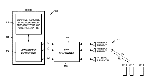
[0013] FIG. IA is a diagram of an adaptive beamforming system according to
some embodiments.
4
Date Recue/Date Received 2023-04-11
88598106
[0014] FIG. 1B illustrates ground-based beamfonning systems according to
some embodiments.
[0015] FIG. 2 illustrates a plurality of spot beam zones.
[0016] FIG. 3 illustrates aspects of the operation of the adaptive
beamforming
system of FIG. 1 according to some embodiments.
[0017] FIG. 4 is a flow diagram of a resource allocation procedure,
according to
some embodiments.
[0018] FIG. 5 illustrates an example of how a user beam is formed according
to
some embodiments.
[0019] FIG. 6 illustrates a spot beam formed by prior art systems.
[0020] FIG. 7 illustrates aspects of the operation of the adaptive
beamforming
system of FIG. 1 according to some embodiments.
[0021] FIG. 8 illustrates an example of return link (RL) beam contours
produced
with the adaptive beamforming system of FIG. 1 according to some embodiments.
[0022] FIG. 9 illustrates an example of return link (RL) beam contours with
a
prior art beamforming system.
[0023] FIG. 10 is a chart illustrating the performance of the adaptive
beamforming
system of FIG. 1 according to some embodiments.
[0024] FIG. 11 is a chart illustrating the performance of the adaptive
beamforming
system of FIG. 1 according to some embodiments.
[0025] FIG. 12 illustrates aspects of the operation of the adaptive
beamforming
system of FIG. 1 according to some embodiments.
4a
Date Recue/Date Received 2023-04-11
CA 03127655 2021-07-22
WO 2020/172408
PCT/US2020/019040
[0026] FIG. 13 is flow diagram illustrating an adaptive user beam startup
procedure,
according to some embodiments.
[0027] FIG. 14 illustrates an adaptive beamforming system according to some
embodiments.
[0028] FIG. 15 is a chart illustrating performance improvements of a user
beam system
over a conventional fixed spot beam system according to some embodiments.
[0029] Skilled artisans will appreciate that elements in the figures are
illustrated for
simplicity and clarity and have not necessarily been drawn to scale. For
example, the
dimensions of some of the elements in the figures may be exaggerated relative
to other
elements to help to improve understanding of embodiments of the present
invention.
[0030] The apparatus and method components have been represented where
appropriate
by conventional symbols in the drawings, showing only those specific details
that are
pertinent to understanding the embodiments of the present invention so as not
to obscure the
disclosure with details that will be readily apparent to those of ordinary
skill in the art having
the benefit of the description herein.
DETAILED DESCRIPTION
[0031] Before any embodiments are explained in detail, it is to be
understood that the
disclosure is not limited in its application to the details of construction
and the arrangement
of components set forth in the following description or illustrated in the
following drawings.
The disclosure is capable of other embodiments and of being practiced or of
being carried out
in various ways.
[0032] It should also be noted that a plurality of hardware and software
based devices, as
well as a plurality of different structural components may be used to
implement aspects of the
disclosure. In addition, it should be understood that embodiments may include
hardware,
software, and electronic components or modules that, for purposes of
discussion, may be
illustrated and described as if the majority of the components were
implemented solely in
hardware. However, one of ordinary skill in the art, and based on a reading of
this detailed
description, would recognize that, in at least one embodiment, the electronics-
based aspects
may be implemented in software (e.g., stored on non-transitory computer-
readable medium)
executable by one or more electronic processors (for example,
microprocessors). As such, it
should be noted that a plurality of hardware and software based devices, as
well as a plurality
of different structural components may be utilized to implement the
disclosure. For example,
"control units" and "controllers" described in the specification can include
one or more
CA 03127655 2021-07-22
WO 2020/172408
PCT/US2020/019040
processors, one or more memory modules including non-transitory computer-
readable
medium, one or more input/output interfaces, and various connections (e.g., a
system bus)
connecting the components.
100331 For ease of description, the example systems or devices presented
herein may be
illustrated with a single exemplar of each of its component parts. Some
examples may not
describe or illustrate all components of the systems. Other example
embodiments may
include more or fewer of each of the illustrated components, may combine some
components,
or may include additional or alternative components.
100341 Embodiments described herein provide individual-user-optimized,
adaptive
beamforming for mobile satellite systems. One example system creates a 'beam
for each
user', referred to as 'user beam' (that is, for communication with user
equipment
participating in the mobile satellite system). As used herein, the term "user
equipment" or
"11E" includes satellite radiotelephones or data terminals, including smart
telephones and access
points for internet of things (loT), wherein the terminal includes a radio
frequency transceiver
and may also include a global positioning system (GPS) or global navigation
satellite system
(GNSS) receiver. The user beam is optimized based either on known user
locations or the
attributes, or signatures, of waveforms received from all cochannel users. The
system
operates in an environment of significant frequency reuse among the cochannel
users. Knowledge of user locations is transferred to the S-BSS (Satellite Base
Station
Subsystem) by the return link or is derived at the S-BSS from estimation of
the spatial
signature of the return link signals with knowledge of pilot signals in the
return link
waveform. The user beam maximizes the signal-to-interference-noise relative to
the desired
user, both in the forward and return links. The optimization process considers
the spatial
distribution of all cochannel users in the footprint of the satellite. The
user beam adapts to
the user's location and co-channel interference environment. By simulation,
the performance
of the beamforming system is compared with an existing fixed beamforming
system, represented by a major GEO MSS covering the Continental United States
and
Canada. The simulation results show that user-optimized adaptive beamforming
offers
significant capacity advantages over the legacy beamforming, measured by
aggregate system
throughput.
[0035] 1. New User Beamforming System and Adaptive Resource Scheduler
[0036] Figure 1A illustrates a high-level block diagram of an adaptive
beamforming
system 100. The described methods may be applied to both cellular networks and
MSS,
although the present narrative treats the latter as the preferred embodiment
for the purpose of
6
CA 03127655 2021-07-22
WO 2020/172408
PCT/US2020/019040
explaining the concepts. Within the MSS category are included both on-board
beamforming,
wherein the beams are formed on the satellite, and ground based beamforming
(GBBF),
where the beams are formed by subsystems of a satellite earth station, or
gateway. The
system block diagram of Figure IA applies, in a general way, to all the above
embodiments.
[0037] The following are the major elements, or subsystems, of the
beamformer system
100.
[0038] Antenna array 102: A fundamental component in a beamformer is an
array of
multiple antennas. The antennas and their feeder electronics (which feed radio
signals to and
from the antenna elements) are often referred to as feed elements.
[0039] Channelizer 104: This subsystem subdivides a broad operating RF
band, for
example, the MSS L-band, into sub-bands that may be more suitable as operating
channel
bandwidths, transmit power amplifiers, and receive low noise amplifiers.
Charmelizers are
more common in satellite systems and may not be necessary in cellular systems
operating
with lower RF bandwidths relative to the operating frequency.
[0040] RF/1F 106: This represents analog electronics that may exist between
the antenna
array and the Satellite Base Station Subsystem (S-BSS). These electronics may
be distributed
between the satellite and the ground based gateway in satellite embodiments,
or the tower
head and radio access network (RAN) equipment in terrestrial cellular
embodiments.
[0041] Satellite Base Station Subsystem (S-BSS) 108: This performs the RAN
functions
of resource scheduling and data/signal processing required by the lower layers
of the protocol
stack. The following explains some differences between how beamforming is
performed in
existing systems and how it is performed in the embodiments discussed herein.
[0042] Traditional beamforming architecture: For transmit operation, a data
stream from
an upper layer of the communication protocol stack is converted into a single
stream of
transmit symbols. These symbols are fed to a beamformer, which may be analog
or digital in
implementation. The beamformer converts the single stream into M symbol-
streams with
appropriate relative amplitudes and phases. The said M streams are then fed to
an M-element
antenna array. For receive operation, the traditional beamformer linearly
combines the M
received symbol streams into a single stream. The combining process applies
appropriate
amplitude weights and phase shifts to each stream. The said single stream is
then provided to
the S-BSS for receive-mode signal/data processing corresponding to the lower
layers of the
communications protocol stack. The above operation is performed for every beam
of the
network.
7
CA 03127655 2021-07-22
WO 2020/172408
PCT/US2020/019040
[0043] New Adaptive Beamformer 110: M symbol streams are passed
transparently (i.e.,
preserving the relative amplitudes and phases of the streams, and with minimal
signal
distortion) to the S-BSS, as shown in Figure 1A. The example system
illustrated in Figure
lA includes an (in-phase and quadrature) interface for use with signals'
center
frequencies, which are at complex baseband. However, a bandpass IF interface
may also be
used without departing from the teachings of the present disclosure.
[0044] Receive Mode Operation: In the receive mode of operation, the S-BSS
receives
an M-element symbol stream (i.e. a stream of complex vectors), instead of a
single (i.e.
scalar) symbol stream. The linear signal processing methods described here may
be used to
adaptively combine the M-streams into a single stream with an improved signal-
to-
interference-plus-noise ratio (SINR). However, because the new architecture
makes available
to the S-BSS a vector of received symbols, as opposed to a post-beamformed
scalar stream,
which would be provided if traditional beamforming had been used, the S-BSS is
able to
apply powerful techniques using vector inputs, including non-linear
techniques, to
demodulate the symbols with greater reliability. Examples of non-linear
techniques are
Decision Feedback and Multiuser Detection.
[0045] Transmit Mode Operation: In the transmit mode, the S-BSS performs
the function
of the beamformer by producing a vector stream instead of scalar stream. The
transmit vector
incorporates the appropriate relative amplitude weights and phase shifts
necessary to create
the desired beams.
[0046] The Receive and Transmit mode beamforming operations described above
are
performed individually for each UE; hence the beam pattern is customized to
the requirements
and operating environment of each UE. It may be noted that, in traditional
beamforming, it is
one beam for many UEs; all UEs in a beam share the spatial attributes of that
beam.
[0047] Adaptive Resource Scheduler (ARS) 112: A RAN resource scheduler is a
common subsystem in existing S-BSS's but is usually very loosely coupled to
the RAN. In
other words, it is typically not responsive to the radio frequency
characteristics of the signals
received by the RAN. In the new architecture, the resource scheduler is
tightly coupled to the
RAN, i.e., it is an essential contributor to the adaptivity of the
beamforining system. For
example, the adaptive resource scheduler (ARS) determines an optimal
frequency, time and
power allocation for each individual user dynamically, based on the spatial
distribution of all
active users and their demands, which may be driven by traffic loads and
Quality of Service
(QOS) requirements.
8
CA 03127655 2021-07-22
WO 2020/172408
PCT/US2020/019040
[0048] Figure 1B is a block diagram of a system where the beamformer is
located on the
ground, which is the architecture (including both old and new embodiments)
corresponding
to aground-based beamformer (GBBF). In the old GBBF architecture 120, the
beamformer
is separate from the Satellite Base Station Subsystem (S-BSS) 108, as is the
current practice,
whereas in the new GBBF architecture 122, the beamforming is integrated in the
S-BSS 108.
[0049] Figure 14 illustrates an example beamforming system 1400 whereby an
existing,
separately beamforming GBBF 1402, depicted in the old architecture of Figure
1A, can be
logically bypassed in order to connect the feed element signals directly to
the S-BSS. The
new adaptive beamformer 1404 may be added to the existing GBBF as additional
capability,
while preserving the existing GBBF's traditional ability to form beams before
the signals are
fed to the S-BSS. Note that, in the new adaptive beamformer, the S-BSS
includes the
beamforming functionality, as in current terrestrial 3GPP systems. According
to the new
architecture, the existing GBBF's weights are designed to transparently
connect the feed
element signals to the S-BSS inputs ¨ one feed element to one input. These
GBBF weights
comprise complex vectors where one element is set to unity (i.e., 1 + j0) and
all other
elements are set to zero; the weight element set to unity depends on the
particular feed
element that is connected to the S-BSS. The advantage of this architecture is
that existing S-
BSS units can continue to be served by the existing GBBF operating in its
traditional modes,
while the new S-BSS can access the feed elements through the existing GBBF
operating in
the pass-through mode. This architecture can be applied to both return link
beamfoiming and
forward link beamforming.
[0050] The motivation for the bypassing of the existing GBBF, described
above, may be
a commercially desire to preserve the present functions of a legacy GBBF with
minimal
disruption, while adding the methods of the present disclosure as added
beamforming options
and implementing them externally (relative to the existing GBBF) in the S-BSS.
It should be
obvious that, in an alternative embodiment, especially in a new
implementation, the new
methods may also be implemented in a standalone GBBF, with the S-BSS
performing its
traditional, exclusively RAN functions. The motivation for this architectural
choice may be
commercial rather than technical. Because of the close coupling between
elements of the
RAN processing, such as the Adaptive RAN Scheduler, and beamforming, the
technically
optimum architecture appears to be a joint RAN Processor and Beamformer, shown
as S-BSS
in Fig. 14, wherein the separate GBBF is either eliminated or bypassed, and
the feed element
signals are connected directly to the S-BSS.
9
CA 03127655 2021-07-22
WO 2020/172408
PCT/US2020/019040
[0051] A new concept, the "beam zone," distinct from operational spotbeams,
is
introduced in the new system. Beam zones are traditional, fixed (non-adaptive)
spotbeams
with an N-color reuse. For example, Figure 2 illustrates a plurality of beam
zones 202 with
the case of N = 3 shown as an example, although N may have any value. The beam
zones
202 are used for frequency planning - they do not represent operational beams.
Figure 3
illustrates how the frequency and power allocation are performed by the system
100. Assume
that a channel bandwidth, B, is available for the new system and, to enable 3-
color frequency
reuse, the band is divided into 3 segments, each having a bandwidth of 1313.
Each beam zone
is allocated spectrum corresponding to one of the 3-color segments. Users
located in a
common beam-zone would share the same 13/3 spectrum through a multiplexing
scheme such
as frequency division multiplexing (FDM). Other multiplexing schemes for
sharing a band
among multiple users could equally be used - the use of FDM in the present
disclosure
should be seen as exemplary rather than essential to the core teachings about
beamforming.
For example, orthogonal frequency division multiplexing, time division
multiplexing, and
code division multiplexing may be used. Note that, typically, the beam zones
may be too
small to allow separation of the users' signals via beamforming, i.e., spatial
multiplexing.
This is owing to the limited aperture of the satellite's antenna array. As in
traditional, fixed
beam design, the beam zones are designed such that cochannel users in adjacent
beam-zones
have a minimum spatial isolation. Typically, the fixed beam design would
incorporate
pattern nulls at a number of control points in the adjacent cochannel beams.
[0052] An example frequency allocation scheme 302 is illustrated in the
Figure 3. As an
example of using FDM for K users inside a beam-zone, the frequency bandwidth
13/3 would
be equally divided among the users with each having B/(3*K) - unequal
distributions of
bandwidth to users could also be used without departing from the present
teachings. This
implies that if there were fewer users inside the beam-zone, the user(s) could
occupy more
bandwidth than if there were more users inside the same beam. The additional
bandwidth
might be used to provide more throughput to the users to improve their Quality
of Service
(QOS) or, alternatively, enable the users to spread their spectrum beyond the
minimum
required for a targeted QOS, thereby using spread spectrum processing gain to
reduce the
interference to other cochannel users. As user locations and distributions
change over the
time, the frequency allocation dynamically adapts to the user situation
accordingly.
[0053] An example resource allocation procedure 400 is summarized in the
flowchart
shown in Figure 4. It starts with the input definition of "beam-zone"
location, shape and size
(at block 402), and frequency reuse ratio N among those "beam-zones- (at block
404), which
CA 03127655 2021-07-22
WO 2020/172408
PCT/US2020/019040
determines the "beam-zone" layout in coverage area (at block 406). Then, based
on the
users' location and distribution (at block 408), the scheduler identifies
users inside each
-beam-zone" (at block 410). Assuming that the total available bandwidth is B
(at block 412)
and that there are K users in a "beam-zone," the scheduler assigns B/(N*K) BW
for each user
inside the -beam-zone" (at block 414).
[0054] In some embodiments, the users inside a "beam-zone" may use all the
B/N
frequency bandwidth through '1'DMA by allocating an exclusive time slot for
each of the
users. In some embodiments, the users may share the B/N frequency bandwidth
through
combination of FDM/TDM such as in OFDMA system. In some embodiments, the users
may share the B/N frequency bandwidth through CDMA, noting that if CDMA were
used, a
frequency reuse corresponding to N=1 may be feasible.
[0055] In distribution of the total EIRP in the forward link, in some
embodiments, the
adaptive resource scheduler may uniformly distribute transmit power among all
active users.
This means that satellite power is distributed proportionally to users'
geographic density.
[0056] Considering the return link, in some embodiments, different users
may be
allocated different amounts of transmit power, proportional to their QOS
needs, which may
be established by a QOS negotiation with an entity in the network
infrastructure (S-BSS or
other entity). The unequal distribution allows different UE types to be
supported in the same
beam-zone.
[0057] The following applies to both forward and return link beamforming.
Once
resource allocations are done, a customized beam is formed for each individual
user with
beam shape adaptive to cochannel UE distribution. The user beam can be formed
with BF
algorithm such as adaptive minimum mean square error (MMSE) based on user
locations or
user reference pilot signals. The pattern generation rule includes maximizing
SINR toward
the desired user with consideration of the actual, spatial distribution of all
cochannel users,
and each user gets a custom beam. With the methods described above, the
adaptive
beamformer is able to optimally utilize degrees of freedom offered by the
antenna feed
element array. Figure 5 illustrates an example of how a user beam 500 is
formed in principle
under the illustrated user distribution scenario. In a conventional system,
illustrated in Figure
6, a fixed regional spot beam 600 is formed for all users in the main beam
602. The fixed
spot beam 600 usually minimizes total received interference plus noise (I+N),
subject to
specified gain constraints for main beam 602 and locations of hypothetical
users in
cochannel-adjacent beams 604, as illustrated in Figure 6. In contrast, as
shown in Figure 5,
the customized user beam 500 maximizes SINR toward the desired user, adaptive
to the
11
CA 03127655 2021-07-22
WO 2020/172408
PCT/US2020/019040
actual, spatial distribution of all cochannel users. The fixed beam 600 of
Figure 6 would
have disadvantages relative to the adaptive beam (user beam 500), such as gain
degradation
and adjacent cochannel beam interference for those users that are near the
beam edge. The
fixed beam 600 of Figure 6 also dedicates the beamformer's degrees of freedom
to optimize
the beam shape for hypothetical desired and undesired users, which may not
represent actual
user distributions or actual interference environment.
[0058] 2. Adaptive Bearufbrming Methods based on user location or waveform
[0059] A customized beam is formed for each individual user with beam shape
adaptive
to cochannel UE distribution, informed by the ARS. The adaptive user
beamfortning
methods for both return link and forward link are described respectively in
this section.
[0060] 2.1 Return link method
[0061] Assume that a satellite (not shown) has a 2-D antenna array 702 of
i'l// feed
element elements (see Figure 7). The in' feed element 704 has the complex
(gain and phase)
response of a m(0,,, TO at azimuth angle 0, and elevation angle of p, from the
satellite point
of view for the km user location 706, as illustrated in Figure 7. The array
steering vector at
the km user location 706 is therefore defined by
a(0,,,yok) = [a 109 k a2(00 gok ), = = = a m(0k,cok)1T EC )
[0062] If K user signals sk (t),k = 0,1,= = = K ¨1, arrive from
(01,(p1),(02, cp,),- = = ,and (0 ) respectively, the array output vector
can be expressed as a
linear combination of the K incident waveforms and noise as below:
K-I
y(t)= Ea(8,,cok)s,(t)+ + n(t)
k=0 (2)
= A s(t) + /(t) + n(t) e curt
[0063] where
A = [a(0,,q),) a(), ) = = = a(0,,q), )1 (3)
[0064] is the array manifold that consists of K steering vectors, and
12
CA 03127655 2021-07-22
WO 2020/172408 PCT/US2020/019040
s(t) = [s, s2() = s, (t) r (4)
[0065] is the vector of signal waveforms, and At) is the vector of
cochannel interference
that may include ancillary terrestrial component (ATC) interference, and n(l)
is the additive
complex Gaussian noise vector. In one embodiment, for a known location of the
kth user at
(8k, co, ) , to form a beam toward the kth user with the MMSE criterion, the
beamformer may
have the weights given by
w = 11;1a(9,,cok) (5)
[0066] where
R = Etyyl (6)
[0067] is the antenna array co-variance matrix.
[0068] In another embodiment, for a known waveform of the kth user skO, to
form a
beam toward the kth user with the MMSE criterion, the beamfonner may have the
weights
given by
w = Wyir (7)
ys
[0069] where
= Etys; (8)
[0070] is the correlation vector between the received vector and reference
signal, which
essentially is the estimated steering vector for the kth user.
[0071] 2.2 Forward link method
[0072] Forward link beamforming is different from return link beamforming
because the
transmit antenna elements and receive antenna elements have different feed
patterns (as a
function of frequency) for an FDD system such as the one in satellite. Also,
unlike the return
13
CA 03127655 2021-07-22
WO 2020/172408
PCT/US2020/019040
link where the received array co-variance matrix Ry can be estimated from the
received array
vector signal yN, the forward link array co-variance matrix obviously does not
exist. In the
case of the forward link, a -virtual transmit array co-variance matrix" is
introduced as a part
of forward link beamforming method.
[0073] As the adaptive scheduler at S-BSS has all information about the
locations of all
the users, and power and bandwidth allocation for all the users, a "virtual
transmit array co-
variance matrix" can be constructed based on this information. In some
embodiments, the
"virtual transmit array co-variance matrix" can be constructed based on
estimated spatial
steering vectors. Assume that scheduler allocates total of K cochannel users
whose carrier
frequency has overlaid one another, and the K cochannel user locations are at
(0 ), (0 2,4) ),= = = ,and (0 ,,,q),) respectively. In addition, the
corresponding allocated
transmit power spectrum densities for the K cochannel users are v 1,p2,
respectively.
Now let's define a cochannel transmit array co-variance matrix as the
following
R,. Ai.(0,T)PA,H(0, go) (9)
[0074] where
AT(19,V) kT('0I,V1) aT(92,4p2) === aT('O K,9K )1
(10)
a1(01,1) a1(02,v2) = = = a1(0õ,y9,,)
a2(01,q)1) (22(02, v2) = = = a2(0.õ,vir)
EC
===
_am(Opcol) am(02õ(o2) === am (9K,co,c)_
[0075] with a m(0 gr) being the inth transmit feed element complex response
at 0, and
Pk
p, 0 = 0
0 0 0
P = p 2,= = = , p,c ) p2
--= . c RKxK (11)
: 0 :
0 0 = pr
14
CA 03127655 2021-07-22
WO 2020/172408
PCT/US2020/019040
[0076] The matrix RT formed in Equation (9) is called as "virtual transmit
array co-
variance matrix". With RT being defined, the forward link beamforming weight
for the /eh
user at location (0,, cod is given by
w = (0,, co, ) (12)
[0077] where
a,(0000 [al(t9k, Sok), a2(0k,q4),... m (0 k, q)k)lT E Cmxi (13)
[0078] is transmit steering vector toward the desired eh user.
[0079] 2.3 Simulation Examples
[0080] The performance of the new user beamforming system versus a
conventional,
fixed (non-adaptive), spot-beamforming system has been investigated with
simulations of an
L-band GEO satellite. The two systems were assumed to have the same number and
spatial
distribution of users. Figure 8 illustrates an example of return link (RL)
beam contours
produced with embodiments of the user beamforming system presented herein,
while Figure
9 illustrates an example of return link (RL) beam contours with the
conventional, fixed spot-
beamforming system. As illustrated in Figure 8, that the user beam 802 puts a
null on each
cochannel user 804 while trying to maximize the gain to the desired user 806.
[0081] To quantify the performance, Monte-Carlo simulations were conducted
to provide
the CDF (cumulative distribution function) of Edlo+No) among all users for the
two systems
(adaptive and fixed). MMSE (Minimum Mean Squared Error) was the optimization
criterion
used for adaptive beamforming and LCMV (Linearly Constrained Minimum Variance)
was
the optimization criterion used for designing the fixed beams. The simulations
show that the
new system offers significantly better performance than the legacy system for
both return link
(RL) and forward link (FL), as shown in Figure 10 and Figure 11, respectively.
The
improvement of user's SINR leads to improvement of the system capacity
(measured as
network-wide aggregate throughput). Figure 15 (chart 1500) further illustrates
the
performance improvements of a user beam system over a conventional fixed spot
beam
system.
[0082] 3. Bootstrapping of a UE in an individual-user optimized adaptive
beamforming
system
CA 03127655 2021-07-22
WO 2020/172408
PCT/US2020/019040
[0083] When a UE tries to initially join the network, there is no user
beam. This section
presents a method to enable a UE to initially join the network and establish a
user beam. We
first introduce the concepts of quiescent state beams and steady state beams.
The quiescent
state beams are the ones used by the S-BSS before a user beam is established
to broadcast
synchronization signals, reference signals, and system information (SI) that
provides essential
information for the UE to operate in the network. The steady state beams are
the adaptively
formed, individual-user-optimized beams generated by the S-BSS in the
connected state. We
refer to the latter as "user beams." The user beam shape adapts to the
distribution of the
ensemble of all cochannel UEs in the footprint of the satellite, while
attempting to maximize
the SNIR of the desired UE. Figure 12 illustrates the S-BSS new beam concept
and
definitions. The fixed regional beams 1202 are used in the quiescent state,
and the user
beams 1204 are used in the steady state (i.e., connected state). The fixed
regional beams
1202 may initially serve the users using a traditional, 3-color frequency
reuse, illustrated as
an example in Figure 12. The use of a frequency reuse factor of 3 is cited as
an example and
is neither essential nor prescriptive. The fixed regional beam may be
optimized to achieve a
desired shape, such as minimum in-beam gain and minimum out-of-beam rejection
at
selected points in the beam's look angle, using algorithms such as the fixed
LCMV. The
beams could be the actual beams for a legacy system.
[0084] The bootstrap procedure for S-BSS system with adaptive user beams
may be air
interface dependent. Figure 13 illustrates one example embodiment of an
adaptive user beam
startup procedure 1300, described in terms of an LTE satellite air interface
for a space-based
network (SBN) 1302 and a user equipment (UE) 1304.
[0085] Step 1 - Fixed regional DL beams broadcast system information (SI),
which is
common to all beams, plus synchronization signals (SS) and reference signals
(RS), which
are unique to each of the fixed beams, as sent to the UE 1304.
[0086] Step 2¨ The UE 1304 scans all the frequency bands supported by the
UE 1304,
and finds the strongest beam as the beam selection candidate.
[0087] Step 3 ¨ The UE 1304 searches for SS to perform time and frequency
synchronizations.
[0088] Step 4 ¨ The UE 1304 synchronizes to the SS to perform beam
identification and
initial frame synchronization.
[0089] Step 5 ¨ The UE 1304 performs system information (SI) acquisition on
downlink
physical broadcast channel (PBCH), which may include system bandwidth, PRACH
(physical random access channel) configuration information.
16
CA 03127655 2021-07-22
WO 2020/172408
PCT/US2020/019040
[0090] Step 6¨ The UE 1304 estimates the uplink timing advance by using its
GPS
location information and the Satellite location information, which improves
overall system
latency and efficiency relative to present 3GPP methods. However, a suitable
adaptation of
the latter may also be used.
[0091] Step 7 ¨ The UE 1304 performs RS based reference signal received
power
(RSRP) measurement and send a PRACH preamble with appropriate PRACH power
level to
request access to the SBN 1302 with the estimated timing advance.
[0092] Step 8 ¨ A Satellite Base Station Subsystem, through the
corresponding Fixed
regional UL beam, detects PRACH preamble and send back random access response
(RAR)
which may contain UL timing command (if any timing adjustment is needed) and
scheduling
information pointing to radio resources that the UE 1304 can use to transmit a
request to
connect.
[0093] Step 9 ¨ The UE 1304 transmits a request to connect which contains
its identity
and location information as part of a Radio Resource Control (RRC) layer
message.
[0094] Step 10¨ The SBN 1302 transmits a connection setup/resume message
and
contention resolution data that resolves any contention due to possible
multiple UEs
transmitting the same preamble in Step 7.
[0095] Step 11 ¨ The UE 1304 replies with a connection setup/resume
complete message
to terminate the random access procedure and complete the transition to
connected state.
[0096] Step 12 - The SBN 1302 forms a user UL beam (receive beam) for the
UE 1304
based on the UE locations or the UE reference pilot signal and network radio
resource
scheduling information, and switches the receive beam from the fixed UL
regional beam to
the user-based UL beam for the UL data packet.
[0097] Step 13 - The SBN 1302 forms a user DL beam (transmit beam) for the
UE 1304
based on the UE locations or the UE reference pilot and network radio resource
scheduling
information, and switches the transmit beam from the fixed DL regional beam to
the user-
based DL beam for the DL data packet.
[0098] Step 14 ¨ The SBN 1302 completes DL/UL data packet in the connected
state.
[0099] Step 15 - The SBN 1302 transmits RRC connection release on PDSCH.
[00100] Step 16 - UE 1304 responds to acknowledge RRC connection release on
PUSCH
RLC.
[00101] 4. Mobility Management fbr User Based Bearnfbrming Space-based Network
(SBN)
17
CA 03127655 2021-07-22
WO 2020/172408
PCT/US2020/019040
[00102] In idle mode, when the MME (mobile management entity) in the core
network
needs to page a UE, it informs the involved user beam entity in the S-BSS, so
that the paging
can be transmitted through the user beam. In that case, the MME has been
keeping UE
history infoimation since an earlier session in the user beam. This assumes
that the device is
stationary since its last access to the network. However, if the device moves
around when in
idle mode, the MME may not have adequate information about the coverage
situation
changes. In this case, some level of MO (mobile originated) traffic may be
used to assist the
MME in keep track of the UE, and thus to improve the DL reachability for the
device. For
example, the network can track the device by using device-triggered location
updates.
[00103] In connected mode, a UE keeps updating its location information so
that the SBN
network can update the user beam weight adaptively to all cochannel user
situations.
Meanwhile the SBN can determine whether the UE is still in the same "regional
beam zone"
from the latest location update. If the UE is moving out of the current zone
and into a
neighboring "regional beam zone", the network starts the handover process by
informing the
UE new frequency and/or time scheduling information and updating the user beam
with new
beam weight accordingly since the beam weight set is dependent on the
frequency allocation.
The handover to the new user beam should be seamless to the user as the user
beam still
maximizes SINR toward the same desired user, only adaptively to the new
cochannel user
situations.
[00104] In the foregoing specification, specific embodiments have been
described.
However, one of ordinary skill in the art appreciates that various
modifications and changes
can be made without departing from the scope of the invention as set forth in
the claims
below. Accordingly, the specification and figures are to be regarded in an
illustrative rather
than a restrictive sense, and all such modifications are intended to be
included within the
scope of present teachings.
[00105] Various features and advantages of some embodiments are set forth in
the
following claims.
18