Language selection

Search

Patent 3127818 Summary

Third-party information liability

Some of the information on this Web page has been provided by external sources. The Government of Canada is not responsible for the accuracy, reliability or currency of the information supplied by external sources. Users wishing to rely upon this information should consult directly with the source of the information. Content provided by external sources is not subject to official languages, privacy and accessibility requirements.

Claims and Abstract availability

Any discrepancies in the text and image of the Claims and Abstract are due to differing posting times. Text of the Claims and Abstract are posted:

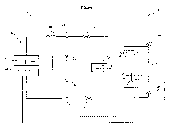
  • At the time the application is open to public inspection;
  • At the time of issue of the patent (grant).
(12) Patent Application: (11) CA 3127818
(54) English Title: BOOST PUMP
(54) French Title: POMPE A CHARGE DE SURVOLTAGE
Status: Examination
Bibliographic Data
(51) International Patent Classification (IPC):
  • F42D 1/045 (2006.01)
  • F42C 11/00 (2006.01)
  • F42C 11/04 (2006.01)
(72) Inventors :
  • KRUGER, MICHIEL JACOBUS (South Africa)
(73) Owners :
  • DETNET SOUTH AFRICA (PTY) LTD
(71) Applicants :
  • DETNET SOUTH AFRICA (PTY) LTD (South Africa)
(74) Agent: OYEN WIGGS GREEN & MUTALA LLP
(74) Associate agent:
(45) Issued:
(86) PCT Filing Date: 2020-01-23
(87) Open to Public Inspection: 2020-08-13
Examination requested: 2023-02-03
Availability of licence: N/A
Dedicated to the Public: N/A
(25) Language of filing: English

Patent Cooperation Treaty (PCT): Yes
(86) PCT Filing Number: PCT/ZA2020/050004
(87) International Publication Number: ZA2020050004
(85) National Entry: 2021-07-23

(30) Application Priority Data:
Application No. Country/Territory Date
2019/00727 (South Africa) 2019-02-04

Abstracts

English Abstract

A detonator installation (10) in which a detonator fire capacitor (36) which is connected in series with an inductor (18) is charged from a low voltage source (16) by repeatedly opening and closing a switch (20) thereby to cause a collapsing magnetic field in the inductor (18) which results in a charging current flow to the capacitor (36).


French Abstract

L'invention concerne une installation de détonateur (10) dans laquelle un condensateur d'amorce de détonateur (36), qui est connecté en série avec une bobine d'induction (18) est chargé à partir d'une source basse tension (16) par l'ouverture et la fermeture répétées d'un commutateur (20), afin de produire un champ magnétique d'effondrement dans la bobine d'induction (18) entraînant un flux de courant de charge vers le condensateur (36).

Claims

Note: Claims are shown in the official language in which they were submitted.

CA 03127818 2021-07-23
WO 2020/163883
PCT/ZA2020/050004
CLAIMS
1. A detonator installation which includes control equipment comprising a
controller, a
voltage source, an inductor and a switch which are connected in series with
the
voltage source, and output terminals, and at least one detonator which
includes a
5 capacitor and at least one protective diode, connected in series to
the output
terminals, wherein the controller is operable repeatedly to close the switch
thereby
to direct current from the voltage source through the inductor which then
establishes
a magnetic field, and to open the switch so that the magnetic field collapses
and
generates a current which flows via the output terminals through the capacitor
and
the diode thereby to charge the capacitor.
2. A detonator installation according to claim 1 wherein the inductor is
physically
removable from the control equipment.
3. A detonator installation according to claim 1 which includes a voltage
limiting
protective device connected in parallel to the detonator, or in parallel to
the output
terminals.

Description

Note: Descriptions are shown in the official language in which they were submitted.


CA 03127818 2021-07-23
WO 2020/163883
PCT/ZA2020/050004
1
BOOST PUMP
BACKGROUND OF THE INVENTION
[0001]This invention relates to a detonator installation which includes
control equipment
and an electronic detonator.
[0002]An electronic detonator includes an ignition element and a fire
capacitor. The fire
capacitor is, in use, charged to a particular voltage and the energy stored in
the capacitor
is discharged in the ignition element, when required, in order to fire the
detonator.
[0003] Electrical energy is supplied to the installation from an electrical
energy source. Due
to current leakage, resistance and other effects, energy losses occur which in
practice give
rise to physical limitations. For example if the electrical losses are such
that the voltage
available to charge a capacitor is too low then the arrangement is not
functional.
[0004]An object of the present invention is to address, at least to some
extent, this aspect.
SUMMARY OF INVENTION
[0005]The invention provides a detonator installation which includes control
equipment
comprising a controller, a voltage source, an inductor and a switch which are
connected in
series with the voltage source, and output terminals, and at least one
detonator which
includes a capacitor and at least one protective diode, connected in series to
the output
terminals, wherein the controller is operable repeatedly to close the switch
thereby to direct
current from the voltage source through the inductor which then establishes a
magnetic
field, and to open the switch so that the magnetic field collapses and
generates a current
which flows via the output terminals through the capacitor and the diode
thereby to charge
the capacitor.

CA 03127818 2021-07-23
WO 2020/163883
PCT/ZA2020/050004
2
[0006]The inductor is preferably physically removable from the control
equipment. The
inductor can thus be used as a key in that, once the inductor is correctly
installed, the
installation is operable but if the inductor is absent the installation is not
operable. This
aspect is, however, optional.
BRIEF DESCRIPTION OF THE DRAWING
[0007]The invention is further described by way of example with reference to
the
accompanying drawing which depicts aspects of a detonator installation
according to the
invention.
DESCRIPTION OF PREFERRED EMBODIMENT
[0008]The accompanying drawing is a schematic illustration of a detonator
installation 10
according to the invention.
[0009]The detonator installation 10 includes control equipment 12 which
comprises a
controller 14 and a voltage source or battery 16.
[0010]An inductor 18, a switch 20 and a protective diode 22 are connected in
series to
output terminals 24 and 26 of the control equipment 12.
[0011]The switch 20 is of any appropriate type e.g. an electronic switch. The
controller 14
is operable to cause repeated closure and opening of the switch 20 in a
regulated manner.
[0012] The controller 14 may be microprocessor-based.
[0013]The installation 10 also includes a detonator 30 which is not shown in
detail. A full
explanation of the workings of the detonator 30 is not necessary for an
understanding of
the present invention. The detonator 30 includes a fire capacitor 36 which is
connected in
parallel to an ignition element 38 and a switch 40 which is under the control
of a control

CA 03127818 2021-07-23
WO 2020/163883
PCT/ZA2020/050004
3
circuit 42. Protective diodes 44 and 46, and resistors 48 and 50, are in
series with the
capacitor 36. The diodes 44, 46 are bridged by a voltage limiting, protective
device 54 e.g.
a Zener diode. The controller 14 may be microprocessor-based.
[0014] In order to charge the capacitor 36 the controller 14 is operated
repeatedly to close
the switch 20 and then to open the switch. When the switch 20 is closed
current from the
voltage source 16 is directed through the inductor 18 and a magnetic field is
established by
the inductor. When the switch 20 is opened the current flow is stopped and the
magnetic
field collapses. Current of a high value is induced by the change in the
magnetic field and
this current flows, via the resistors 48 and 50 and the diodes 44 and 46, and
charges the
capacitor 36.
[0015]With each cycle of operation of the switch 20 i.e. closure and opening
thereof, an
electrical charge is imparted to the capacitor 36. The voltage across the
capacitor thus
builds up in bursts. To prevent the capacitor 36 from being overcharged in
this way the
device 54 "breaks down" at a predetermined voltage and, as it is in parallel
with the capacitor
36, the device 54 prevents current from flowing through the capacitor 36.
[0016]The described arrangement makes it possible for the capacitor 36 to be
charged in
a safe and effective manner from the voltage source 16 which has a relatively
low voltage
compared to the comparatively high voltage which is established over the
capacitor 36 when
it is correctly charged. When the ignition element 38 is to be fired this is
effected by means
of the switch 40 which functions under the control of the circuit 42.
[0017]The low voltage required to charge the capacitor 36 means that the
control
equipment 12 can be made intrinsically safe i.e. it does not have a voltage on-
board which
is of a high enough value to fire the detonator 30. It is not possible to
charge the capacitor

CA 03127818 2021-07-23
WO 2020/163883
PCT/ZA2020/050004
4
36 unless at least one of the diodes 44 and 46 is present. A particular safety
feature is that
the inductive coil 18 can be used as a key to enable the detonator
installation to become
operative. If the coil 18 is physically removed (disconnected) from the
control equipment 12
then charging of the capacitor 36 is not possible. This is a useful safety
feature.
[0018]The use of the device 54 is optional for inclusion of the device is not
necessary for
the voltage boosting process to be achieved. Also, it is possible to position
the device 54
directly across the terminals 22 and 24 in order to limit the current that can
be delivered to
the detonator 30.
[0019]The voltage boost process, carried out in the described manner, means
that the
energy leakage problem referred to in the preamble hereof is addressed. As
noted in a
typical circuit if voltage starvation is pronounced the likelihood increases
that the available
voltage, at the end of an extended line of detonators, might be insufficient
to charge the fire
capacitor. The technique described herein allows for substantial energy
leakage to take
place while still maintaining the capability to charge the fire capacitor
successfully.

Representative Drawing
A single figure which represents the drawing illustrating the invention.
Administrative Status

2024-08-01:As part of the Next Generation Patents (NGP) transition, the Canadian Patents Database (CPD) now contains a more detailed Event History, which replicates the Event Log of our new back-office solution.

Please note that "Inactive:" events refers to events no longer in use in our new back-office solution.

For a clearer understanding of the status of the application/patent presented on this page, the site Disclaimer , as well as the definitions for Patent , Event History , Maintenance Fee  and Payment History  should be consulted.

Event History

Description Date
Letter Sent 2024-01-23
Inactive: Office letter 2023-03-08
Letter Sent 2023-03-01
Refund Request Received 2023-02-10
Request for Examination Received 2023-02-03
Request for Examination Requirements Determined Compliant 2023-02-03
All Requirements for Examination Determined Compliant 2023-02-03
Inactive: Request Received Change of Agent File No. 2023-01-19
Common Representative Appointed 2021-11-13
Inactive: Cover page published 2021-10-13
Letter sent 2021-08-23
Priority Claim Requirements Determined Compliant 2021-08-20
Inactive: IPC assigned 2021-08-17
Application Received - PCT 2021-08-17
Inactive: First IPC assigned 2021-08-17
Request for Priority Received 2021-08-17
National Entry Requirements Determined Compliant 2021-07-23
Application Published (Open to Public Inspection) 2020-08-13

Abandonment History

There is no abandonment history.

Maintenance Fee

The last payment was received on 2023-01-11

Note : If the full payment has not been received on or before the date indicated, a further fee may be required which may be one of the following

  • the reinstatement fee;
  • the late payment fee; or
  • additional fee to reverse deemed expiry.

Patent fees are adjusted on the 1st of January every year. The amounts above are the current amounts if received by December 31 of the current year.
Please refer to the CIPO Patent Fees web page to see all current fee amounts.

Fee History

Fee Type Anniversary Year Due Date Paid Date
Basic national fee - standard 2021-07-23 2021-07-23
MF (application, 2nd anniv.) - standard 02 2022-01-24 2022-01-12
MF (application, 3rd anniv.) - standard 03 2023-01-23 2023-01-11
Request for examination - standard 2024-01-23 2023-02-03
Owners on Record

Note: Records showing the ownership history in alphabetical order.

Current Owners on Record
DETNET SOUTH AFRICA (PTY) LTD
Past Owners on Record
MICHIEL JACOBUS KRUGER
Past Owners that do not appear in the "Owners on Record" listing will appear in other documentation within the application.
Documents

To view selected files, please enter reCAPTCHA code :


To view images, click a link in the Document Description column (Temporarily unavailable). To download the documents, select one or more checkboxes in the first column and then click the "Download Selected in PDF format (Zip Archive)" or the "Download Selected as Single PDF" button.

List of published and non-published patent-specific documents on the CPD .

If you have any difficulty accessing content, you can call the Client Service Centre at 1-866-997-1936 or send them an e-mail at CIPO Client Service Centre.

({010=All Documents, 020=As Filed, 030=As Open to Public Inspection, 040=At Issuance, 050=Examination, 060=Incoming Correspondence, 070=Miscellaneous, 080=Outgoing Correspondence, 090=Payment})


Document
Description 
Date
(yyyy-mm-dd) 
Number of pages   Size of Image (KB) 
Description 2021-07-22 4 149
Abstract 2021-07-22 2 59
Representative drawing 2021-07-22 1 11
Drawings 2021-07-22 1 12
Claims 2021-07-22 1 25
Courtesy - Letter Acknowledging PCT National Phase Entry 2021-08-22 1 588
Courtesy - Acknowledgement of Request for Examination 2023-02-28 1 423
Commissioner's Notice - Maintenance Fee for a Patent Application Not Paid 2024-03-04 1 552
International search report 2021-07-22 2 55
National entry request 2021-07-22 5 160
Request for examination 2023-02-02 4 105
Refund 2023-02-09 5 134
Courtesy - Office Letter 2023-03-07 1 165