Sélection de la langue

Search

Sommaire du brevet 3127818 

Énoncé de désistement de responsabilité concernant l'information provenant de tiers

Une partie des informations de ce site Web a été fournie par des sources externes. Le gouvernement du Canada n'assume aucune responsabilité concernant la précision, l'actualité ou la fiabilité des informations fournies par les sources externes. Les utilisateurs qui désirent employer cette information devraient consulter directement la source des informations. Le contenu fourni par les sources externes n'est pas assujetti aux exigences sur les langues officielles, la protection des renseignements personnels et l'accessibilité.

Disponibilité de l'Abrégé et des Revendications

L'apparition de différences dans le texte et l'image des Revendications et de l'Abrégé dépend du moment auquel le document est publié. Les textes des Revendications et de l'Abrégé sont affichés :

  • lorsque la demande peut être examinée par le public;
  • lorsque le brevet est émis (délivrance).
(12) Demande de brevet: (11) CA 3127818
(54) Titre français: POMPE A CHARGE DE SURVOLTAGE
(54) Titre anglais: BOOST PUMP
Statut: Examen
Données bibliographiques
(51) Classification internationale des brevets (CIB):
  • F42D 1/045 (2006.01)
  • F42C 11/00 (2006.01)
  • F42C 11/04 (2006.01)
(72) Inventeurs :
  • KRUGER, MICHIEL JACOBUS (Afrique du Sud)
(73) Titulaires :
  • DETNET SOUTH AFRICA (PTY) LTD
(71) Demandeurs :
  • DETNET SOUTH AFRICA (PTY) LTD (Afrique du Sud)
(74) Agent: OYEN WIGGS GREEN & MUTALA LLP
(74) Co-agent:
(45) Délivré:
(86) Date de dépôt PCT: 2020-01-23
(87) Mise à la disponibilité du public: 2020-08-13
Requête d'examen: 2023-02-03
Licence disponible: S.O.
Cédé au domaine public: S.O.
(25) Langue des documents déposés: Anglais

Traité de coopération en matière de brevets (PCT): Oui
(86) Numéro de la demande PCT: PCT/ZA2020/050004
(87) Numéro de publication internationale PCT: ZA2020050004
(85) Entrée nationale: 2021-07-23

(30) Données de priorité de la demande:
Numéro de la demande Pays / territoire Date
2019/00727 (Afrique du Sud) 2019-02-04

Abrégés

Abrégé français

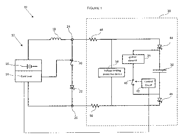
L'invention concerne une installation de détonateur (10) dans laquelle un condensateur d'amorce de détonateur (36), qui est connecté en série avec une bobine d'induction (18) est chargé à partir d'une source basse tension (16) par l'ouverture et la fermeture répétées d'un commutateur (20), afin de produire un champ magnétique d'effondrement dans la bobine d'induction (18) entraînant un flux de courant de charge vers le condensateur (36).


Abrégé anglais

A detonator installation (10) in which a detonator fire capacitor (36) which is connected in series with an inductor (18) is charged from a low voltage source (16) by repeatedly opening and closing a switch (20) thereby to cause a collapsing magnetic field in the inductor (18) which results in a charging current flow to the capacitor (36).

Revendications

Note : Les revendications sont présentées dans la langue officielle dans laquelle elles ont été soumises.


CA 03127818 2021-07-23
WO 2020/163883
PCT/ZA2020/050004
CLAIMS
1. A detonator installation which includes control equipment comprising a
controller, a
voltage source, an inductor and a switch which are connected in series with
the
voltage source, and output terminals, and at least one detonator which
includes a
5 capacitor and at least one protective diode, connected in series to
the output
terminals, wherein the controller is operable repeatedly to close the switch
thereby
to direct current from the voltage source through the inductor which then
establishes
a magnetic field, and to open the switch so that the magnetic field collapses
and
generates a current which flows via the output terminals through the capacitor
and
the diode thereby to charge the capacitor.
2. A detonator installation according to claim 1 wherein the inductor is
physically
removable from the control equipment.
3. A detonator installation according to claim 1 which includes a voltage
limiting
protective device connected in parallel to the detonator, or in parallel to
the output
terminals.

Description

Note : Les descriptions sont présentées dans la langue officielle dans laquelle elles ont été soumises.


CA 03127818 2021-07-23
WO 2020/163883
PCT/ZA2020/050004
1
BOOST PUMP
BACKGROUND OF THE INVENTION
[0001]This invention relates to a detonator installation which includes
control equipment
and an electronic detonator.
[0002]An electronic detonator includes an ignition element and a fire
capacitor. The fire
capacitor is, in use, charged to a particular voltage and the energy stored in
the capacitor
is discharged in the ignition element, when required, in order to fire the
detonator.
[0003] Electrical energy is supplied to the installation from an electrical
energy source. Due
to current leakage, resistance and other effects, energy losses occur which in
practice give
rise to physical limitations. For example if the electrical losses are such
that the voltage
available to charge a capacitor is too low then the arrangement is not
functional.
[0004]An object of the present invention is to address, at least to some
extent, this aspect.
SUMMARY OF INVENTION
[0005]The invention provides a detonator installation which includes control
equipment
comprising a controller, a voltage source, an inductor and a switch which are
connected in
series with the voltage source, and output terminals, and at least one
detonator which
includes a capacitor and at least one protective diode, connected in series to
the output
terminals, wherein the controller is operable repeatedly to close the switch
thereby to direct
current from the voltage source through the inductor which then establishes a
magnetic
field, and to open the switch so that the magnetic field collapses and
generates a current
which flows via the output terminals through the capacitor and the diode
thereby to charge
the capacitor.

CA 03127818 2021-07-23
WO 2020/163883
PCT/ZA2020/050004
2
[0006]The inductor is preferably physically removable from the control
equipment. The
inductor can thus be used as a key in that, once the inductor is correctly
installed, the
installation is operable but if the inductor is absent the installation is not
operable. This
aspect is, however, optional.
BRIEF DESCRIPTION OF THE DRAWING
[0007]The invention is further described by way of example with reference to
the
accompanying drawing which depicts aspects of a detonator installation
according to the
invention.
DESCRIPTION OF PREFERRED EMBODIMENT
[0008]The accompanying drawing is a schematic illustration of a detonator
installation 10
according to the invention.
[0009]The detonator installation 10 includes control equipment 12 which
comprises a
controller 14 and a voltage source or battery 16.
[0010]An inductor 18, a switch 20 and a protective diode 22 are connected in
series to
output terminals 24 and 26 of the control equipment 12.
[0011]The switch 20 is of any appropriate type e.g. an electronic switch. The
controller 14
is operable to cause repeated closure and opening of the switch 20 in a
regulated manner.
[0012] The controller 14 may be microprocessor-based.
[0013]The installation 10 also includes a detonator 30 which is not shown in
detail. A full
explanation of the workings of the detonator 30 is not necessary for an
understanding of
the present invention. The detonator 30 includes a fire capacitor 36 which is
connected in
parallel to an ignition element 38 and a switch 40 which is under the control
of a control

CA 03127818 2021-07-23
WO 2020/163883
PCT/ZA2020/050004
3
circuit 42. Protective diodes 44 and 46, and resistors 48 and 50, are in
series with the
capacitor 36. The diodes 44, 46 are bridged by a voltage limiting, protective
device 54 e.g.
a Zener diode. The controller 14 may be microprocessor-based.
[0014] In order to charge the capacitor 36 the controller 14 is operated
repeatedly to close
the switch 20 and then to open the switch. When the switch 20 is closed
current from the
voltage source 16 is directed through the inductor 18 and a magnetic field is
established by
the inductor. When the switch 20 is opened the current flow is stopped and the
magnetic
field collapses. Current of a high value is induced by the change in the
magnetic field and
this current flows, via the resistors 48 and 50 and the diodes 44 and 46, and
charges the
capacitor 36.
[0015]With each cycle of operation of the switch 20 i.e. closure and opening
thereof, an
electrical charge is imparted to the capacitor 36. The voltage across the
capacitor thus
builds up in bursts. To prevent the capacitor 36 from being overcharged in
this way the
device 54 "breaks down" at a predetermined voltage and, as it is in parallel
with the capacitor
36, the device 54 prevents current from flowing through the capacitor 36.
[0016]The described arrangement makes it possible for the capacitor 36 to be
charged in
a safe and effective manner from the voltage source 16 which has a relatively
low voltage
compared to the comparatively high voltage which is established over the
capacitor 36 when
it is correctly charged. When the ignition element 38 is to be fired this is
effected by means
of the switch 40 which functions under the control of the circuit 42.
[0017]The low voltage required to charge the capacitor 36 means that the
control
equipment 12 can be made intrinsically safe i.e. it does not have a voltage on-
board which
is of a high enough value to fire the detonator 30. It is not possible to
charge the capacitor

CA 03127818 2021-07-23
WO 2020/163883
PCT/ZA2020/050004
4
36 unless at least one of the diodes 44 and 46 is present. A particular safety
feature is that
the inductive coil 18 can be used as a key to enable the detonator
installation to become
operative. If the coil 18 is physically removed (disconnected) from the
control equipment 12
then charging of the capacitor 36 is not possible. This is a useful safety
feature.
[0018]The use of the device 54 is optional for inclusion of the device is not
necessary for
the voltage boosting process to be achieved. Also, it is possible to position
the device 54
directly across the terminals 22 and 24 in order to limit the current that can
be delivered to
the detonator 30.
[0019]The voltage boost process, carried out in the described manner, means
that the
energy leakage problem referred to in the preamble hereof is addressed. As
noted in a
typical circuit if voltage starvation is pronounced the likelihood increases
that the available
voltage, at the end of an extended line of detonators, might be insufficient
to charge the fire
capacitor. The technique described herein allows for substantial energy
leakage to take
place while still maintaining the capability to charge the fire capacitor
successfully.

Dessin représentatif
Une figure unique qui représente un dessin illustrant l'invention.
États administratifs

2024-08-01 : Dans le cadre de la transition vers les Brevets de nouvelle génération (BNG), la base de données sur les brevets canadiens (BDBC) contient désormais un Historique d'événement plus détaillé, qui reproduit le Journal des événements de notre nouvelle solution interne.

Veuillez noter que les événements débutant par « Inactive : » se réfèrent à des événements qui ne sont plus utilisés dans notre nouvelle solution interne.

Pour une meilleure compréhension de l'état de la demande ou brevet qui figure sur cette page, la rubrique Mise en garde , et les descriptions de Brevet , Historique d'événement , Taxes périodiques et Historique des paiements devraient être consultées.

Historique d'événement

Description Date
Lettre envoyée 2024-01-23
Inactive : Lettre officielle 2023-03-08
Lettre envoyée 2023-03-01
Demande de remboursement reçue 2023-02-10
Requête d'examen reçue 2023-02-03
Exigences pour une requête d'examen - jugée conforme 2023-02-03
Toutes les exigences pour l'examen - jugée conforme 2023-02-03
Inactive : Demande reçue chang. No dossier agent 2023-01-19
Représentant commun nommé 2021-11-13
Inactive : Page couverture publiée 2021-10-13
Lettre envoyée 2021-08-23
Exigences applicables à la revendication de priorité - jugée conforme 2021-08-20
Inactive : CIB attribuée 2021-08-17
Demande reçue - PCT 2021-08-17
Inactive : CIB en 1re position 2021-08-17
Demande de priorité reçue 2021-08-17
Exigences pour l'entrée dans la phase nationale - jugée conforme 2021-07-23
Demande publiée (accessible au public) 2020-08-13

Historique d'abandonnement

Il n'y a pas d'historique d'abandonnement

Taxes périodiques

Le dernier paiement a été reçu le 2023-01-11

Avis : Si le paiement en totalité n'a pas été reçu au plus tard à la date indiquée, une taxe supplémentaire peut être imposée, soit une des taxes suivantes :

  • taxe de rétablissement ;
  • taxe pour paiement en souffrance ; ou
  • taxe additionnelle pour le renversement d'une péremption réputée.

Les taxes sur les brevets sont ajustées au 1er janvier de chaque année. Les montants ci-dessus sont les montants actuels s'ils sont reçus au plus tard le 31 décembre de l'année en cours.
Veuillez vous référer à la page web des taxes sur les brevets de l'OPIC pour voir tous les montants actuels des taxes.

Historique des taxes

Type de taxes Anniversaire Échéance Date payée
Taxe nationale de base - générale 2021-07-23 2021-07-23
TM (demande, 2e anniv.) - générale 02 2022-01-24 2022-01-12
TM (demande, 3e anniv.) - générale 03 2023-01-23 2023-01-11
Requête d'examen - générale 2024-01-23 2023-02-03
Titulaires au dossier

Les titulaires actuels et antérieures au dossier sont affichés en ordre alphabétique.

Titulaires actuels au dossier
DETNET SOUTH AFRICA (PTY) LTD
Titulaires antérieures au dossier
MICHIEL JACOBUS KRUGER
Les propriétaires antérieurs qui ne figurent pas dans la liste des « Propriétaires au dossier » apparaîtront dans d'autres documents au dossier.
Documents

Pour visionner les fichiers sélectionnés, entrer le code reCAPTCHA :


Pour visualiser une image, cliquer sur un lien dans la colonne description du document (Temporairement non-disponible). Pour télécharger l'image (les images), cliquer l'une ou plusieurs cases à cocher dans la première colonne et ensuite cliquer sur le bouton "Télécharger sélection en format PDF (archive Zip)" ou le bouton "Télécharger sélection (en un fichier PDF fusionné)".

Liste des documents de brevet publiés et non publiés sur la BDBC .

Si vous avez des difficultés à accéder au contenu, veuillez communiquer avec le Centre de services à la clientèle au 1-866-997-1936, ou envoyer un courriel au Centre de service à la clientèle de l'OPIC.

({010=Tous les documents, 020=Au moment du dépôt, 030=Au moment de la mise à la disponibilité du public, 040=À la délivrance, 050=Examen, 060=Correspondance reçue, 070=Divers, 080=Correspondance envoyée, 090=Paiement})


Description du
Document 
Date
(aaaa-mm-jj) 
Nombre de pages   Taille de l'image (Ko) 
Description 2021-07-22 4 149
Abrégé 2021-07-22 2 59
Dessin représentatif 2021-07-22 1 11
Dessins 2021-07-22 1 12
Revendications 2021-07-22 1 25
Courtoisie - Lettre confirmant l'entrée en phase nationale en vertu du PCT 2021-08-22 1 588
Courtoisie - Réception de la requête d'examen 2023-02-28 1 423
Avis du commissaire - non-paiement de la taxe de maintien en état pour une demande de brevet 2024-03-04 1 552
Rapport de recherche internationale 2021-07-22 2 55
Demande d'entrée en phase nationale 2021-07-22 5 160
Requête d'examen 2023-02-02 4 105
Remboursement 2023-02-09 5 134
Courtoisie - Lettre du bureau 2023-03-07 1 165