Note: Descriptions are shown in the official language in which they were submitted.
CA 03128254 2021-07-28
WO 2020/256798 PCT/US2020/019900
A UNIVERSAL FEEDER FOR A GASIFICATION REACTOR
[0001] This application is a Continuation-in-part Application of US
Application No. 16/723,538
filed December 20, 2019 which is a Continuation-in-part of US Application No.
16/445,118 filed
6/18/2019 which is a Continuing Application of US Application No. 15/725,637
filed 10/5/2017;
which is a Continuation-in-part of US Application No. 14/967,973 filed
12/14/2015 now US Pat.
No. 9,809,769 issued 11/7/2017; which is a Divisional Application of US
Application No.
13/361,582 filed 1/30/2012 now US Pat. No. 9,242,219 issued 1/26/2016, all of
which are
incorporated herein in their entirety.
FIELD
[0002] The present invention relates in general to the field of feedstock
disposal including
sewage sludge treatment (SST), municipal solid waste (MSW) management, wood
waste (WW)
processing, refuse derived fuels (RDF) treatment, Automotive Shredder Residue
(ASR) and non-
recyclable plastics disposal (NRP). Target markets for the present
invention include
municipalities, landfill operators that clean up and rehabilitate land, waste
generators, wastewater
treatment facilities, agricultural waste generators, private waste service
companies and
entrepreneurs invested in renewable energy.
BACKGROUND
[0003] Currently the combination of a fluidized bed or bubbling bed gasifier
include a feeder
system for biosolids that are designed for a single specific feedstock. It is
a common practice in
the industry that these gasification systems have similar feeder devices but
require specialized
design features to accommodate specific feedstock related to their respective
handling
requirements. These are often cumbersome, complex and expensive. What's needed
is a
standardized device and method of feeding diverse feedstock into the reactor
chambers of any
gasifier.
1
CA 03128254 2021-07-28
WO 2020/256798 PCT/US2020/019900
SUMMARY
[0004] The invention is a standardized feeder system designed for a gasifier
system to enable
different feedstock materials to be fed to existing gasification reactors
without having to custom
design the feed system or integrate the feeder into the reactor. The present
invention is a universal
feeder system that combines with a fluidized bed gasification reactor for the
treatment of multiple
or mixed feedstocks including but not limited to sewage sludge, municipal
solid waste, wood
waste, refuse derived fuels, automotive shredder residue and non-recyclable
plastics. The
invention thereby also illustrates a method of gasification for multiple
and/or diverse feedstocks
using a universal feeder system.
[0005] The feeder system consists of one or more feed vessels attached to a
live bottom dual screw
feeder. In one embodiment, the feed vessel is rectangular shaped having three
vertical sides and
an angled side of no less than 60 degrees from the horizontal to facilitate
proper flow of bio-
feedstock materials that have different and/or variable flow properties. The
vessel also provides
for aeration mechanisms such as provided by inserting removable bridge
breakers to safeguard
flows. The biosolids are transferred from the live bottom dual screw feeder
through a chute and
into a secondary transfer screw feeder that conveys the material to a feed
nozzle operably
connected to a gasifier reactor. The secondary transfer screw is equipped with
a coolant jacket to
maintain a feed temperature between 60 F ¨ 200 F further expanding the types
of feedstock that
can be conveyed into a gasifier reactor.
[0006] This invention allows for standardizing equipment design and
commoditization in the
gasification industry by providing a path for simpler gasifier design with
fewer equipment
components. The universal feeder system may be used in open air, under ambient
pressure and
low temperature conditions. Where odor control is required, the systems can be
fitted with a
removable standard containment panel. In the case of biosolids, this design of
the system may be
a closed system from the feed bin into the gasifier to address odor control.
Explosion panels are
also optional for explosible dusts.
2
CA 03128254 2021-07-28
WO 2020/256798 PCT/US2020/019900
[0007] The invention is used for receiving and conveying bio-feedstock
materials into any
bioreactor. The feeder system is specifically suitable for categories of waste
currently being
landfilled, that could be incinerated if permitting new incinerations were
possible or that have
restricted recycling options to safely and fully dispose of these waste
materials. The present
invention can be used by municipalities, landfill operators that clean up and
rehabilitate land, waste
generators, wastewater treatment facilities, agricultural waste generators,
private waste service
companies and entrepreneurs invested in renewable energy. It could also be
used in analogous
non-gasification processes to convey metered solids to storage tanks, for
desegregation in
recycling of waste.
[0008] Currently there is no prior art of a single universal feeder/gasifier
system capable of
processing a broad range of feedstocks. Prior art dictates providing for
custom designed feedstock-
specific feeder systems to handle a specific type of feedstock. This in turn
leads to modification
and redesign of the gasifier. The present invention solves this problem and in
addition, the present
design can switch between different bio-feedstocks during operations.
BRIEF DESCRIPTION OF THE DRAWINGS
[0009] FIG. 1 shows a side view of a gasifier reactor and schematic block
diagram illustrating
an embodiment of the feeder system configuration for bio-feedstocks.
[0010] FIG. 2 shows a schematic side view illustrating a fluidized bed
gasifier in accordance
with an embodiment of the invention.
[0011] FIG. 3 shows a perspective view illustrating a tuyere type gas
distributor of the gasifier
in accordance with an embodiment of the invention.
[0012] FIG. 4 shows a schematic side view illustrating a mid-size non-limiting
example of a
gasifier's internal dimensions in accordance with an embodiment of the
invention.
[0013] FIG. 5 shows a schematic side view illustrating a smaller non-limiting
example of a
gasifier's internal dimensions in accordance with an embodiment of the
invention.
3
CA 03128254 2021-07-28
WO 2020/256798 PCT/US2020/019900
[0014] FIG. 6 shows a schematic side view illustrating a larger non-limiting
example of a
gasifier's internal dimensions in accordance with an embodiment of the
invention.
[0015] FIG. 7 shows a schematic side view illustrating the larger scaled up
fluidized bed gasifier
of FIG.6 in accordance with an embodiment of the invention.
[0001] FIG. 8A shows a cut away perspective view illustrating a pipe gas
distributor of the
gasifier in accordance with an embodiment of the invention.
[0002] FIG. 8B shows a side el evational view illustrating a pipe gas
distributor of the gasifier
in accordance with an embodiment of the invention.
[0003] FIG. 9 shows a perspective view of multiple universal gasifier feeder
systems connected
to a gasifier in accordance with an embodiment of the invention.
[0004] FIG. 10 shows a top view of multiple feeder systems and a single
gasifier system with
multiple feed points in accordance with an embodiment of the invention.
[0005] FIG. 11 shows a side view of the universal gasifier feeder system with
a cut away
view of a gasifier to which the feeder system is attached in accordance with
an embodiment of
the invention.
DETAILED DESCRIPTION
[0006] The foregoing and other objects, features, and advantages of the
invention will be
apparent from the following more particular description of preferred
embodiments as illustrated
in the accompanying drawings, in which reference characters refer to the same
parts throughout
the various views. The drawings are not necessarily to scale, emphasis instead
being placed
upon illustrating principles of the invention. Reference will now be made in
detail to the various
exemplary embodiments of the present invention, which are illustrated in the
accompanying
drawings.
4
CA 03128254 2021-07-28
WO 2020/256798 PCT/US2020/019900
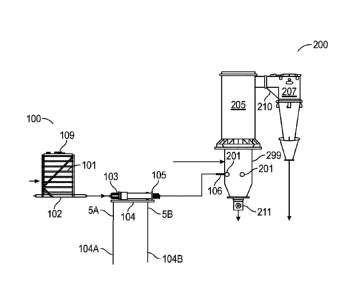
[0007] Figure 1 shows a side view of a gasifier reactor and a schematic
diagram illustrating an
embodiment of the feeder system 100 configuration for feedstocks which is
generally received in
a vertically oriented feed vessel 101 meeting industry standard feedstock
supply specifications.
The system comprises one or more feed vessels 101 each operably connected to a
live bottom dual
screw feeder 102. In one embodiment, the feed vessel is rectangular shaped
having at least one of
its four sides angled at least 60 degrees 110 (shown in FIG. 9) from the
horizontal to facilitate
proper flow of bio-feedstock materials that have different and/or variable
flow properties. The
vessel also provides for aeration mechanisms such as provided by aeration
ports 107 (shown in
FIG. 9) and or removable bridge breakers (not shown) that are inserted on the
interior of the feed
vessel 101 to assist with continuous flow. The live bottom dual screw feeder
102 is conventional
industry equipment selected for their ability to transport multiple kinds of
feedstock and as such is
not limited to sewage sludge, municipal solid waste, wood waste, refuse
derived fuels, automotive
shredder residue and non-recyclable plastics including blends of two or more
biosolids feed stocks
such as wood waste plus biosolids.
[0008] Screw feeder 102 also called screw conveyors and are used to control
the flow rate of both
free and non-free flowing, bulk material from a bin, silo or hopper. Live
bottom feeders are
specifically designed to convey and meter large quantities of materials in a
very efficient manner.
During operation the inlet section of the screw trough is designed to be
flooded with a selected
material. The screw under the inlet can be modified to convey a metered amount
of material per
revolution of the screw. Modifications include but are not limited to in the
fighting diameter,
pitch, pipe diameter, trough shape. Screws with uniform diameter and pitch
will convey material
from the rear of the inlet opening to the front. The drives on screw feeders
attached to the rear
end, are usually variable speed, so that the discharge from a bin, hopper or
feed vessel 101 that
falls onto the screw feeder 102 and trough 102A can be adjusted, as required,
to stay within a
prescribed range. Depending on the number of screws across the bottom of the
bin, hopper or feed
vessel 101, there may be one drive for all the screws, several drives with the
screws driven in-
groups or individual drives for each screw.
CA 03128254 2021-07-28
WO 2020/256798 PCT/US2020/019900
[0009] The biosolids are transferred by gravity from the live bottom dual
screw feeder 102 through
an open bottom chute 111 and onto a secondary transfer screw feeder 103 that
conveys the material
to a feed nozzle 106 operably connected such as by a flange to flange
connection to a fuel feed
inlet 201 located on the gasifier reactor vessel 299. The secondary transfer
screw 103 may be
equipped with a coolant jacket 104 with a cooling water supply 104A and a
cooling water return
104B to maintain a feedstock temperature between 60 F ¨ 200 F. This feature
further expands the
types of feedstock that can be conveyed into a gasifier reactor. Screw feeders
102 can be
substituted with other industry feeders or pressurized pneumatic conveyors.
Pressurized
pneumatic conveyors would allow the invention to be used in and with a
pressurized gasification
system and other transfer designs. All screw feeders 102 and transfer screw
feeders 103 are
variable speed and motor operated. Although it is possible in another
embodiment that the screw
feed can be manually operated as with a crank.
[0010] In one embodiment, the live bottom dual screw feeder 102 can operate to
direct the flow
of feedstock in a single direction. In another embodiment, the dual screw
feeder 102 can operate
to direct flow of feedstock in two different directions. The feedstock can be
fed into a gasifier
reactor vessel 299 from more than one feed vessel 101 through multiple fuel
feed inlets 201 located
on the gasifier reactor vessel 299. A live bottom dual screw feeder 102 may
therefore feed two
separate transfer screw feeders 103; but the transfer screw feeder 103 may
also connect and feed
another secondary or even tertiary transfer screw feeder 103 as shown in FIG.
4. Each screw
feeder connection transfers the biosolids by gravity through an open bottom
chute 111 onto the
connecting screw feeder until the screw feeder 103 terminates and mechanically
connects to the
fluidized fuel inlets 201 on the gasifier reactor vessel 299.
[0011] The feed vessels 101 may also be sized such that appropriately
distributed volumes of
feedstock are maintained entering the gasifier through multiple feed ports.
The fuel feed inlets
201, also called feed ports, may be placed all around the gasifier vessel
reactor 299 to ensure a
continuous feed of fuel into the gasifier system 200. The feed vessel 101
inventory may be
controlled through load cells or level sensors 105 (shown on FIGS. 9 and 11).
Particle size and
moisture of the feedstock may be measured upstream of and on route to the feed
vessel port 109
to ensure optimum control and performance output of the gasifier system 200.
6
CA 03128254 2021-07-28
WO 2020/256798 PCT/US2020/019900
[0012] In one embodiment, the feeder system 100 is capable of receiving and
processing multiple
feedstocks prepared to a size up to one inch with an optimal range between
1/46 and 1/4 inches. A
key requirement of this embodiment is prepping the feedstock to a uniform
size, moisture content
and quality which is achieved through conventional processes. Prepared
feedstock is then
introduced into the vessel feed port 109 of the universal feeder vessel 101
and ultimately the
gasification reactor vessel 299 for gasification.
[0013] Figure 2 shows an embodiment of a bubbling type fluidized bed gasifier
200. In one
embodiment, the invention is mechanically connected to a standardized feeder
system 100
(shown in FIG. 1) which is designed for a gasifier 200 that enables different
feedstock material to
be fed into existing gasification reactor vessel 299 without having to custom
design a feed system
for or integrate a custom feeder system into the gasifier system 200. In one
embodiment, the
bubbling fluidized bed gasifier 200 will include a reactor 299 operably
connected to the feeder
system 100 as integral part of a standard gasifier system 200.
[0014] In continued refence to FIG. 2, the bubbling fluidized bed gasifier 200
will include a reactor
299 operably connected to a feeder system 100 (shown in FIG.1) as an extended
part of a standard
gasifier system 200. In one embodiment, the gasifier 200 includes a reactor
vessel 299 having
a fluidized media bed 204A, such as but not limited to quartz sand, that is in
the base of the
reactor vessel and called the reactor bed section 204. In one embodiment, the
fluidized sand is a
zone that has a temperature of 1150-1600 F. Located above the reactor bed
section 204 is a
transition section 204B and above the transition section 204B is the freeboard
section 205 of the
reactor vessel 299. Fluidizing gas consisting of air, flue gas, pure oxygen or
steam, or a
combination thereof, is introduced into the fluidized bed reactor 299 to
create a velocity range
inside the freeboard section 205 of the gasifier 200 that is in the range of
0.1 m/s (0.33 ft/s)
to 3 m/s (9.84 ft/s). The biosolids are heated inside the fluidized bed
reactor to a temperature
range between 900 F and 1700 F in an oxygen-starved environment having sub-
stoichiometric
levels of oxygen, e.g., typically oxygen levels of less than 45% of
stoichiometric.
7
CA 03128254 2021-07-28
WO 2020/256798 PCT/US2020/019900
[0015] The reactor fluidized bed section 204 of a fluidized bubbling bed
gasifier 200 is filled with
a fluidizing media 204A that may be a sand (e.g., quartz or olivine), or any
other suitable fluidizing
media known in the industry. Feedstock such as, but not limited to dried
biosolids, is supplied to
the reactor bed section 204 through fuel feed inlets 201 at 40-250 F. In one
embodiment, the
feedstock is supplied to the reactor bed section 204 through fuel feed inlets
201 at 215 F; with the
gas inlet 203 in the bubbling bed receiving an oxidant-based fluidization gas
such as but not
limited to e.g., air. In one embodiment, the air could be enriched air, or a
mix of air and recycled
flue gas, etc. The air is not pre-heated, it is fed at ambient conditions. The
bed is heated up with
natural gas and air combustion from a start-up burner and when the bed reaches
its ignition
temperature for gasification the reactions takes off and is self-sustaining so
long as feed carbon
and oxygen continue to react. The fluidization gas is fed to the bubbling bed
via a gas distributor,
such as shown in FIGS. 3 and 8A-B. An oxygen-monitor 209 may be provided in
communication
with the fluidization gas inlet 203 to monitor oxygen concentration in
connection with controlling
oxygen levels in the gasification process. An inclined or over-fire natural
gas burner (not visible)
located on the side of the reactor vessel 299 receives a natural gas and air
mixture via a port 202.
In one embodiment, the natural gas air mixture is 77 F which can be used to
start up the gasifier
and heat the fluidized bed media 204A. When the minimum ignition temperature
for self-
sustaining of the gasification reactions is reached (-900 F), the natural gas
is shut off View ports
206 and a media fill port 212 are also provided.
[0016] In one embodiment, a freeboard section 205 is provided between the
fluidized bed section
204 and the producer gas outlet 210 of the gasifier reactor vessel 299. As the
biosolids thermally
decompose and transform in the fluidized bed media section (or sand zone) into
producer gas and
then rise through the reactor vessel 299, the fluidizing medium 204A in the
fluidized bed section
204 is disentrained from the producer gas in the freeboard section 205 which
is also known as and
called a particle disengaging zone. A cyclone separator 207 may be provided to
separate material
exhausted from the fluidized bed reactor 299 resulting in clean producer gas
for recovery with ash
exiting the bottom of the cyclone separator 207 alternatively for use or
disposal.
[0017] An ash grate 211 may be fitted below the gasifier vessel for bottom ash
removal. The ash
grate 211 may be used as a sifting device to remove any large inert,
agglomerated or heavy particles
8
CA 03128254 2021-07-28
WO 2020/256798 PCT/US2020/019900
so that the fluidizing media and unreacted char can be reintroduced into the
gasifier for continued
utilization. In one embodiment, a valve such as but not limited to slide valve
213 which is operated
by a mechanism to open the slide valve 214 is located beneath the ash grate
211 to collect the ash.
In one embodiment, a second valve 213 and operating mechanism 214 (no shown)
are also located
below the cyclone separator 207 for the same purpose. That is as a sifting
device to remove any
large inert, agglomerated or heavy particles so that the fluidizing media and
unreacted char can be
reintroduced into the gasifier for continued utilization. In one embodiment,
the ash grate 211 may
be a generic solids removal device known to those of ordinary skill in the
art. In another
embodiment, the ash grate 211 may be replaced by or combined with the use of
an overflow nozzle.
[0018] A producer gas control 208 monitors oxygen and carbon monoxide levels
in the producer
gas and controls the process accordingly. In one embodiment a gasifier feed
system 100 feeds the
gasifier reactor 299 through the fluidized fuel inlets 201. In one embodiment,
the gasifier unit 200
is of the bubbling fluidized bed type with a custom fluidizing gas delivery
system and multiple
instrument control. The gasifier reactor 299 provides the ability to
continuously operate, discharge
ash and recycle flue gas for optimum operation. The gasifier reactor 299 can
be designed to
provide optimum control of feed rate, temperature, reaction rate and
conversion of varying
feedstock into producer gas.
[0019] A number of thermocouple probes (not shown) are placed in the gasifier
reactor 299 to
monitor the temperature profile throughout the gasifier. Some of the thermal
probes are placed in
the fluidized bed section 204 of the gasifier rector 299, while others are
placed in the freeboard
section 205 of the gasifier. The thermal probes placed in the fluidized bed
section 204 are used
not only to monitor the bed temperature but are also control points that are
coupled to the gasifier
air system via port 202 in order to maintain a certain temperature profile in
the bed of fluidizing
media. There are also a number of additional control instruments and sensors
that may be placed
in the gasifier system 200 to monitor the pressure differential across the bed
section 204 and the
operating pressure of the gasifier in the freeboard section 205. These
additional instruments are
used to monitor the conditions within the gasifier as well to as control other
ancillary equipment
and processes to maintain the desired operating conditions within the
gasifier. Examples of such
ancillary equipment and processes include but are not limited to the cyclone,
thermal oxidizer and
9
CA 03128254 2021-07-28
WO 2020/256798 PCT/US2020/019900
recirculating flue gas system and air delivery systems. These control
instruments and sensors are
well known in the industry and therefore not illustrated.
[0020] Figure 3 shows a perspective cut away side view illustrating a gas
distributor 302 of
the gasifier in accordance with an embodiment of the invention. A flue gas and
air inlet 203
feeds flue gas and air to an array of nozzles 301. Each of the nozzles
includes downwardly
directed ports inside cap 303 such that gas exiting the nozzle is initially
directed downward
before being forced upward into the fluidized bed in the reactor bed section
204 (shown in
FIG. 2). An optional ash grate 211 under the gasifier may be used as a sifting
device to
remove any agglomerated particles so that the fluidizing media and unreacted
char can be
reintroduced into the gasifier for continued utilization. Also shown is a cut
away view of the gas
inlet 203 in the bubbling bed receiving an oxidant-based fluidization gas such
as but not limited
to e.g., air.
BIOGASIFIER REACTOR SIZING
[0021] The following provides a non-limiting example illustrating computation
of the best
dimensions for a bubbling fluidized bed gasification reactor in accordance
with an embodiment
of the invention. The gasifier, in this example, is sized to accommodate two
specific operating
conditions: The current maximum dried biosolids output generated from the
dryer with respect
to the average solids content of the dewatered sludge supplied to the dryer
from the existing
dewatering unit; and the future maximum dried biosolids feed rate that the
dryer will have to
deliver to the gasifier if the overall biosolids processing system has to
operate without
consumption of external energy, e.g., natural gas, during steady state
operation with 25% solids
content dewatered sludge being dried and 5400 lb/hr of water being evaporated
from the sludge.
[0022] The first operating condition corresponds to the maximum output of
dried sewage
sludge from the dryer if, e.g., 16% solids content sludge is entering the
dryer, and 54001b/hr of
water is evaporating off the sludge. This corresponds to a biosolids feed rate
in the small-
scale gasifier of 1,168 lbs/hr of thermally dried biosolids at 10% moisture
content entering the
gasifier. In one embodiment, a solids content of 16-18% represents the
estimated extent of
dewatering that is required to make the drying load equal to the amount of
thermal energy
CA 03128254 2021-07-28
WO 2020/256798 PCT/US2020/019900
which can be recovered from the flue gas and used to operate the dryer. If
sludge below 16%
solids content are processed in the dryer, an external heat source can
supplement the drying
process. The second operating condition corresponds to the maximum amount of
dried biosolids
(dried to 10% moisture content) that the drier can produce if 25% solids
content dewatered
biosolids is fed into the drier. The second condition corresponds to the
gasifier needing to
process 2,000 lb/hr of 10% moisture content biosolids. In other words, there
will be excess heat
from feeding biosolids to the gasifier if greater than 20% content of
biosolids in the sludge is used.
[0023] Figure 4 shows a non-limiting example of the gasifier with a reactor
freeboard diameter
of 9 feet, 0 inches and other internal dimensions in accordance with the
invention. The
dimensions shown satisfy the operational conditions that are outlined in
previous applications.
As is known in the art, one factor in determining gasifier sizing is the bed
section internal
diameter. The role of the bed section of the reactor is to contain the
fluidized media bed. The
driving factor for selecting the internal diameter of the bed section of the
gasifier is the
superficial velocity range of gases, which varies with different reactor
internal diameters. The
internal diameter has to be small enough to ensure that the media bed is able
to be fluidized
adequately for the given air, recirculated flue gas and fuel feed rates at
different operating
temperatures, but not so small as to create such high velocities that a
slugging regime occurs
and media is projected up the freeboard section. The media particle size can
be adjusted
during commissioning to fine tune the fluidizing behavior of the bed. In the
present, non-
limiting example, an average media (sand) particle size of about 700 m was
selected due to its
ability to be fluidized readily, but also its difficulty to entrain out of the
reactor. The most
difficult time to fluidize the bed is on start up when the bed media and
incoming gases are
cold. This minimum flow rate requirement is represented by the minimum
fluidization velocity,
("Umf) values displayed in the previous table.
[0024] Another factor in determining gasifier sizing is the freeboard section
internal diameter.
The freeboard region of the gasifier allows for particles to drop out under
the force of gravity.
The diameter of the freeboard is selected with respect to the superficial
velocity of the gas
mixture that is created from different operating temperatures and fuel feed
rates. The gas
superficial velocity must be great enough to entrain the small ash particles,
but not so great that
11
CA 03128254 2021-07-28
WO 2020/256798 PCT/US2020/019900
the media particles are entrained in the gas stream. The extent of fresh fuel
entrainment should
also be minimized from correct freeboard section sizing. This is a phenomenon
to carefully
consider in the case of biosolids gasification where the fuel typically has a
very fine particle
size. Introducing the fuel into the side of the fluidized bed below the
fluidizing media's
surface is one method to minimize fresh fuel entrainment. This is based on the
principle that
the fuel has to migrate up to the bed's surface before it can be entrained out
of the gasifier, and
this provides time for the gasification reactions to occur.
[0025] In one non-limiting example shown in FIG. 5, a reactor with freeboard
diameter of 4
feet, 9 inches is chosen for smaller volumes of feed of about 24 tons per day
but also to maintain
gas superficial velocities high enough to entrain out ash but prevent
entrainment of sand (or
other fluidizing media) particles in the bed.
[0026] A further factor in determining gasifier sizing is the media bed depth
and bed section
height. In general, the higher the ratio of media to fuel in the bed, the more
isothermic the
bed temperatures are likely to be. Typically, fluidized beds have a fuel-to-
media mass ratio of
about 1-3%. The amount of electrical energy consumed to fluidize the media bed
typically
imparts a practical limit on the desirable depth of the media. Deeper beds
have a higher gas
pressure drop across them and more energy is consumed by the blower to
overcome this
resistance to gas flow. A fluidizing media depth of 3 feet is chosen in this
example shown
in FIG. 5, which is based on balancing the blower energy consumption against
having enough
media in the bed to maintain isothermal temperature and good heat transfer
rates. The height
of the bed section of the reactor in this non-limiting example is based on a
common length-
to- diameter aspect ratio of 1.5, relative to the depth of the fluidizing
media.
[0027] Another factor in determining gasifier sizing is the height of the
freeboard section 205.
The freeboard section 205 is designed to drop out particles and return it to
the bed, under the
force of gravity and a reduction of superficial velocity as a result of the
larger diameter in the free
board section. As one moves up in elevation from the bed's surface, the
particle size and
density decreases, until at a certain elevation, a level known as the
Transport Disengaging
Height (TDH) is reached. Above the TDH, the particle density entrained up the
reactor is
12
CA 03128254 2021-07-28
WO 2020/256798 PCT/US2020/019900
constant. Extending the reactor above the TDH adds no further benefit to
particle removal.
For practical purposes 10 feet is selected for the height of the freeboard
section 205 in
this non-limiting example shown in FIG. 5. While the invention has been
particularly shown
and described with reference to a preferred embodiment in FIG. 5, it will be
understood by
those skilled in the art that various changes in form and details may be made
therein without
departing from the spirit and scope of the invention.
[0028] FIG. 6 shows a schematic side view illustrating a larger scaled-up
embodiment is
provided in which the gasifier internal dimensions are enlarged in accordance
with the invention.
In this embodiment, the invention illustrates a scaling up or enlargement of
the gasifier reactor
vessel. In one embodiment, the increase in reactor vessel size has a capacity
scale that is at least
4 times larger in processing feedstock volume than the small-scale reactor
vessel shown in FIG. 5.
For example, the small-scale reactor can process 24 tons per day of feedstock.
The large-scale
reactor can process more than 40 tons per day with an average of about 100
tons per day of
feedstock. At an average of 100 tons per day of feedstock equals an average of
at least 4 times
that of the small-scale reactor of 24 tons per day which is equal to about 96
tons per day. In one,
embodiment, of the scaled-up large format reactor, the multi-tuyere gas
distributor shown in FIG.
3 is replaced with a conventional pipe-based fluidization gas distribution
system shown in FIGS.
8A-8B. The substitution of the pipe-based distributor 800 simplifies and
eliminates the
complexity, time and cost associated with the mechanical fabrication of
scaling up the multi-tuyere
gas distributor design used in the bioreactor unit illustrated in FIG. 3. A
conventional pipe-based
fluidization gas distribution system allows a single large vessel reactor
capable of processing at
least 4 times the quantity of feedstock processed in a small-scale reactor.
The larger scale reactor
illustrated in FIGS. 6-7 has many of the same features as the smaller scaled
version illustrated in
FIGS. 2 and 5. However, some adjustments to the reactor bed and free-board
height are required
based on the change in diameter of the reactor bed section. The formula for
Transport Disengaging
Height ("TDH") is a function of the change in diameter of the reactor bed
section 704 shown in
FIG. 7. Specifically, the geometric ratios remain the same to
minimize/eliminate performance
scale-up risk.
13
CA 03128254 2021-07-28
WO 2020/256798 PCT/US2020/019900
[0029] FIG. 6 also shows a non-limiting example illustrating computation of
the sample
dimensions for sizing the gasifier reactor when it is a bubbling fluidized bed
gasification reactor.
More specifically, FIG. 6 shows a non-limiting example of the gasifier with a
reactor freeboard
diameter of 11 feet, 5 inches and other internal dimensions in accordance with
the invention.
The gasifier, in this example, is sized to accommodate specific design
operating conditions for
dried biosolids feed rate delivered to the gasifier corresponding to a
biosolids feed rate in the large-
scale gasifier of 8,333 lb/hr and 7040 lb/hr of thermally dried biosolids at
10% moisture content
entering the gasifier.
[0030] Figure 7 shows a scaled-up embodiment of a bubbling type fluidized bed
gasifier 700. In
one embodiment, the bubbling fluidized bed gasifier 700 will include a reactor
799 operably
connected to the feeder system (shown in FIG. 1) as an extended part of the
standard gasifier
system 700. A fluidized media bed 704A such as but not limited to quartz sand
is in the base of
the reactor vessel called the reactor bed section 704. In one embodiment, the
fluidized sand is a
zone that has a temperature of 1150 F-1600 F. Located above the reactor bed
section 704 is a
transition section 704B and above the transition section 704B is the freeboard
section 705 of the
reactor vessel 799. Fluidizing gas consisting of air, flue gas, pure oxygen or
steam, or a
combination thereof, is introduced into the fluidized bed reactor 799 to
create a velocity range
inside the freeboard section 705 of the gasifier 700 that is in the range of
0.1 m/s (0.33 ft/s)
to 3 m/s (9.84 ft/s). The biosolids are heated inside the fluidized bed
reactor to a temperature
range between 900 F and 1600 F in an oxygen-starved environment having sub-
stoichiometric
levels of oxygen, e.g., typically oxygen levels of less than 45% of
stoichiometric. In another
embodiment, the fluidized sand is a zone that has a temperature of 1150 F-1600
F.
[0031] The reactor fluidized bed section 704 of a fluidized bubbling bed
gasifier 700 is filled with
a fluidizing media 704A that may be a sand (e.g., quartz or olivine), or any
other suitable fluidizing
media known in the industry. Feedstock such, as but not limited to sludge, is
supplied to the reactor
bed section 704 through fuel feed inlets 701 at 40-250 F. In one embodiment,
the feedstock is
supplied to the reactor bed section 704 through fuel feed inlets 701 at 215 F;
with the gas inlet 703
in the bubbling bed receiving an oxidant-based fluidization gas such as but
not limited to e.g., gas,
flue gas, recycled flue gas, air, enriched air and any combination thereof
(hereafter referred to
14
CA 03128254 2021-07-28
WO 2020/256798 PCT/US2020/019900
generically as "gas" or "air"). In one embodiment, the air is at about 600 F.
The type and
temperature of the air is determined by the gasification fluidization and
temperature control
requirements for a particular feedstock. The fluidization gas is fed to the
bubbling bed via a gas
distributor, such as shown in FIGS. 3 and 8A-B. An oxygen-monitor 709 may be
provided in
communication with the fluidization gas inlet 703 to monitor oxygen
concentration in connection
with controlling oxygen levels in the gasification process. An inclined or
over-fire natural gas
burner (not visible) located on the side of the reactor vessel 799 receives a
natural gas and air
mixture via a port 702. In one embodiment, the natural gas air mixture is 77 F
which can be sued
to start up the gasifier and heat the fluidized bed media 704A. When the
minimum ignition
temperature for self-sustaining of the gasification reactions is reached (-900
F), the natural gas is
shut off. View ports 706 and a media fill port 712 are also provided.
[0032] In one embodiment, a freeboard section 705 is provided between the
fluidized bed section
704 and the producer gas outlet 710 of the gasifier reactor vessel 799. As the
biosolids thermally
decompose and transform in the fluidized bed media section (or sand zone) into
producer gas and
then rise through the reactor vessel 799, the fluidizing medium 704A in the
fluidized bed section
704 is disentrained from the producer gas in the freeboard section 705 which
is also known as and
called a particle disengaging zone. A cyclone separator 707 may be provided to
separate material
exhausted from the fluidized bed reactor 799 resulting in clean producer gas
for recovery with ash
exiting the bottom of the cyclone separator 707 alternatively for use or
disposal.
[0033] An ash grate 711 may be fitted below the gasifier vessel for bottom ash
removal. The ash
grate 711 may be used as a sifting device to remove any large inert,
agglomerated or heavy particles
so that the fluidizing media and unreacted char can be reintroduced into the
gasifier for continued
utilization. In one embodiment, a valve such as but not limited to slide valve
713 which is operated
by a mechanism to open the slide valve 714 is located beneath the ash grate
711 to collect the ash.
In one embodiment, a second valve 713 and operating mechanism 714 (no shown)
are also located
below the cyclone separator 207 for the same purpose. That is as a sifting
device to remove any
large inert, agglomerated or heavy particles so that the fluidizing media and
unreacted char can be
reintroduced into the gasifier for continued utilization. In one embodiment
the ash grate 711 may
CA 03128254 2021-07-28
WO 2020/256798 PCT/US2020/019900
be a generic solids removal device known to those of ordinary skill in the
art. In another
embodiment, the ash grate 711 may be replaced by or combined with the use of
an overflow nozzle.
[0034] A producer gas control 708 monitors oxygen and carbon monoxide levels
in the producer
gas and controls the process accordingly. In one embodiment. a gasifier feed
system (shown in
FIGs 1 and 9-11) feeds the gasifier reactor 799 through the fluidized fuel
inlets 701. In one
embodiment, the gasifier unit 700 is of the bubbling fluidized bed type with a
custom fluidizing
gas delivery system and multiple instrument control. The gasifier reactor 799
provides the ability
to continuously operate, discharge ash and recycle flue gas for optimum
operation. The gasifier
reactor 799 can be designed to provide optimum control of feed rate,
temperature, reaction rate
and conversion of varying feedstock into producer gas.
[0035] A number of thermocouple probes (not shown) are placed in the gasifier
reactor 799 to
monitor the temperature profile throughout the gasifier. Some of the thermal
probes are placed in
the fluidized bed section 704 of the gasifier rector 799, while others are
placed in the freeboard
section 705 of the gasifier. The thermal probes placed in the fluidized bed
section 704 are used
not only to monitor the bed temperature but are also control points that are
coupled to the gasifier
air system via port 702 in order to maintain a certain temperature profile in
the bed of fluidizing
media. There are also a number of additional control instruments and sensors
that may be placed
in the gasifier system 700 to monitor the pressure differential across the bed
section 704 and the
operating pressure of the gasifier in the freeboard section 205. These
additional instruments are
used to monitor the conditions within the gasifier as well to as control other
ancillary equipment
and processes to maintain the desired operating conditions within the
gasifier. Examples of such
ancillary equipment and processes include but are not limited to the cyclone,
thermal oxidizer and
recirculating flue gas system and air delivery systems. These control
instruments and sensors are
well known in the industry and therefore not illustrated.
[0036] With reference to FIG.7, an optional ash grate 711 may be fitted below
the gasifier vessel
for bottom ash removal. The ash grate 7 11 may be used as a sifting device to
remove any
agglomerated particles so that the fluidizing media and unreacted char can be
reintroduced into
the gasifier for continued utilization. In one embodiment, a slide valve 713
operated by a
16
CA 03128254 2021-07-28
WO 2020/256798 PCT/US2020/019900
mechanism to open the slide valve 714 is located beneath the ash grate 711 to
collect the ash. In
one embodiment, a second slide valve 713 and operating mechanism 714 are
located below the
cyclone separator 707.
[0037] As with the small format fluidized bed gasifier, some unreacted carbon
is carried into the
cyclone separator 707 with particle sizes ranging from 10 to 300 microns. When
the solids
are removed from the bottom of the cyclone, the ash and unreacted carbon can
be separated
and much of the unreacted carbon recycled back into the gasifier, thus
increasing the overall
fuel conversion to at least 95%. Ash accumulation in the bed of fluidizing
media may be
alleviated through adjusting the superficial velocity of the gases rising
inside the reactor.
Alternatively, bed media and ash could be slowly drained out of the gasifier
base and
screened over an ash grate 7 11 before being reintroduced back into the
gasifier. This process
can be used to remove small agglomerated particles should they form in the bed
of fluidizing
media and can also be used to control the ash-to-media ratio within the
fluidized bed.
[0038] With continued reference to FIG. 7, a feedstock such as but not limited
to biosolid material
can be fed into the gasifier by way of the fuel feed inlets 701 from more than
one location on the
reactor vessel 799 and wherein said fuel feed inlets 701 may be variably sized
such that the desired
volumes of feedstock are fed into the gasifier through multiple feed inlets
701 around the reactor
vessel 799 to accommodate a continuous feed process to the gasifier. For the
present invention
and in one embodiment, the number of fuel feed inlets is between 2-4. The
minimum number of
feed inlets 701 is based, in part, on the extent of extent of back mixing and
radial mixing of the
char particles in the bed and on the inside diameter of the reactor bed
section 704. For bubbling
fluidized beds, one feed point could be provided per 20 ft2 of bed cross
sectional area. For
example, and in one embodiment, if the reaction bed section has an internal
diameter of 9 ft, the
reactor vessel 799 will have at least 3 feed inlets 701 which may be located
equidistant radially to
maintain in-bed mixing. Feed inlets 701 may be considered all on one level, or
on more than one
level or different levels and different sizes.
[0039] FIG. 8A shows a cut away perspective view illustrating a pipe gas
distributor of the
biogasifier in accordance with an embodiment of the invention. FIG. 8B shows a
side
17
CA 03128254 2021-07-28
WO 2020/256798 PCT/US2020/019900
elevational view illustrating a pipe gas distributor of the biogasifier in
accordance with an
embodiment of the invention. In one embodiment, the invention has a pipe
distributor design with
a main air inlet 801, said main air inlet 801 having an upper portion 801A and
lower portion 801B.
In one embodiment, the lower portion 801B is connected a pipe 812 such as but
not limited to an
elbow or j -pipe. In one embodiment, the lower portion 801B is connected to a
pipe 812 using a
male mounting seal that is connected to a female mounting seal 803 that is
connected to a female
mounting stub that is connected to the pipe 812. In one embodiment, the pipe
812 has a proximal
end 812A and terminal end 812B wherein the proximal end 812A is mechanically
connected to
the main air inlet 801 and the terminal end 812B is connected to the gas inlet
703. In one
embodiment, the pipe 812B terminal end has a flange 811 to connect to the gas
inlet 703.
[0040] The upper portion of the main air inlet 801A is aligned with and an
opening in a center
trunk line 806, said trunk line 806 having at least 10 lateral air branches
805 that are open on one
end to the center trunk line and closed on the other end. In one embodiment
the lateral air branches
805 are symmetrically spaced on either side of the center trunk line 806. In
one embodiment, the
lateral air branches 805 are of varying length to fit symmetrically within the
diameter of the bottom
of the reactor bed 204. In one embodiment, each of the lateral air branches
805 comprise
downward pointing gas and air distribution nozzles 810 which are also called,
gas and air
distribution ports 810. The air distribution nozzles 810 are pointed downward
so the air entering
from the main air inlet 801 is injected in a downward motion into the cone-
shaped bottom of the
gasifier reactor 799. In one embodiment the distribution nozzles 810 point
downward at an angle
such as but not limited to a 45-degree angle. The configuration and general
locations of nozzles
and components differ from the tuyere design for the smaller reactor vessel in
that fewer gas/air
distribution nozzles are required in a tuyere design to meet the fluidization
requirements and good
mixing requirements but still enough to enable the full volume of the
fluidizing media material to
fluidize when slumped in the bottom cone section of the reactor. This is also
an essential part of
the reactor.
[0041] FIG 9. shows a perspective view of multiple universal gasifier feeder
systems connected
to a gasifier in accordance with an embodiment of the invention. With
reference to FIG. 9 the
feedstock is gravity fed from a feed port 109 located on top to the feeder
vessel 101. In one
18
CA 03128254 2021-07-28
WO 2020/256798 PCT/US2020/019900
embodiment, the vessel 101 is rectangular shaped having three vertical sides
and an angled side
110. The angled side 110 has a slope of no less than 60 degrees from the
horizontal to facilitate
proper flow of bio-feedstock materials that have different and/or variable
flow properties. At least
one side of the vessel 101 needs to be angled, although the vertical sides can
also be between
vertical and a have a negative angle between 0 and 15 degrees. The no less
than 60-degree angle
110 together with aeration using aeration ports 107 (shown in FIG. 11) and
other means such as
inserting removable bridge breakers (not shown) located within the vessel 101
can assist with and
modulate flow of vary feedstock.
[0042] The length of the live bottoms dual screw 102 and transfer screw 103
may vary and depend
in the space available to locate the vessel 101 and distance to the gasifier
200. The transfer screw
103 may be equipped with a cooling jacket 104 shown in FIG. 1 in the event of
the feedstock or
feedstock combinations has a recommended minimum flammability temperature that
requires the
feedstock to be cooled. In one embodiment, the feed system 1 00 includes more
than one
transfer screw 103 that can operate as metering screws that are then connected
to a transfer screw
that can operate as a high-speed injection screw conveying the feedstock into
the gasifier
reactor vessel 299. In one embodiment, load cells or metering screw systems
are used in place of
the live bottoms dual screw and transfer screw to control the feed rate to the
gasifier.
[0043] FIG. 10 shows a top view of multiple feeder systems 100 and a single
gasifier reactor
vessel 299 with sample screw connections and multiple feed points via the fuel
deed inlets 201 in
accordance with an embodiment of the invention.
[0044] FIG. 11 shows a side view of the universal gasifier feeder system 100
with a cut
away view of a gasifier reactor vessel 299 to which the transfer screw 103 of
the feeder system is
attached via at least fuel feed inlet 201 of the gasifier 200 in accordance
with an embodiment of
the invention. In one embodiment, the transfer screw 103 terminates at the
fuel feed inlet 201. In
another embodiment, the transfer screw 103 protrudes into the bed section 204
of the reactor vessel
299. In this embodiment, sample bin capacity is shown as 3.5 tons of feedstock
for a single feed
vessel with an internal temperature of the feed vessel at 200 F. In one
embodiment, the internal
operating temperature of the gasifier reactor 299 is about 1200 F. Multiple
sensors (not shown)
19
CA 03128254 2021-07-28
WO 2020/256798 PCT/US2020/019900
can be included to monitor pressure and temperature within the reactor vessel.
One such sensor
such as feed level sensors 105. Another embodiment may also include a feed
view port 108 located
on the open bottom chute 111.
[0045] The location of the aeration ports 107 can be variable in size and
location and on any side
of the vessel. The number of ports 107 can also be increased or decreased
depending on the type
and number of bridge breaking features and size of the feed vessel 101.
Adjustable aeration
features that uses either air or an inert gas, assists with avoiding bridging
and maintaining flow to
the transfer screws 103. The feed vessel 101 terminates in an open bottom
chute 111 and a live
bottoms dual screw feeder design 102 is located below the chute 111. The screw
feeder 102
conveys the feedstock to another open bottom chute 111 that drops the
feedstock by gravity
directly onto the transfer screw 103. The screw feeder 103 conveys the
feedstock either to another
transfer screw feeder 103 by the same gravity/chute mechanism or conveys the
feedstock to a
gasifier reactor 299 via a fluidized fuel feed inlet 201. The connection of
the transfer screw 103
to the feed inlet 201 is mechanical such as by a flange 116 to flange 116
connection.
[0046] The present invention makes processing large volumes of feedstock in
either a single- or
multi-gasifier system and building large industrial facilities feasible and
cost effective; replacing
the current and commonly practiced use of multiple smaller units. More
specifically, the present
invention is universal feeder system that combines with a fluidized bed
gasification reactor for the
treatment of multiple diverse feedstocks including sewage sludge, municipal
solid waste, wood
waste, refuse derived fuels, automotive shredder residue and non-recyclable
plastics. The
invention thereby also illustrates a method of gasification for multiple and
diverse feedstocks using
a universal feeder system. The feeder system comprises one or more feed
vessels and at least one
live bottom dual screw feeder.
[0047] The feed vessel is rectangular shaped having three vertical sides and
an angled side of no
less than 60 degrees from the horizontal to facilitate proper flow of
feedstock material that have
different and/or variable flow properties. The feedstocks are transferred
through an open bottom
chute to a live bottom dual screw feeder and through another open bottom chute
to a transfer screw
feeder that conveys feedstock to the fuel feed inlets of a gasifier. The
invention is designed for
CA 03128254 2021-07-28
WO 2020/256798 PCT/US2020/019900
the biomass waste processing industry - standardizes the capacity scale to a
single design from 10-
24tpd day to more than 40tpd and an average of over 100tpd of feedstock that
can be used at a
single facility and retain the economies of scale. It also cooperatively can
work with other standard
large-scale supporting equipment such as driers, pollution control equipment
and thermal handling
equipment. This allows for standardized system and equipment design and
commoditization.
[0048] While various embodiments of the present invention have been described
above, it should
be understood that they have been presented by way of example only, and not of
limitation.
Likewise, the various diagrams may depict an example architectural or other
configuration for the
invention, which is provided to aid in understanding the features and
functionality that can be
included in the invention. The invention is not restricted to the illustrated
example architectures
or configurations, but the desired features can be implemented using a variety
of alternative
architectures and configurations.
[0049] Indeed, it will be apparent to one of skill in the art how alternative
functional configurations
can be implemented to implement the desired features of the present invention.
Additionally, with
regard to operational descriptions and method claims, the order in which the
steps are presented
herein shall not mandate that various embodiments be implemented to perform
the recited
functionality in the same order unless the context dictates otherwise.
[0050] Although the invention is described above in terms of various exemplary
embodiments and
implementations, it should be understood that the various features, aspects
and functionality
described in one or more of the individual embodiments are not limited in
their applicability to the
particular embodiment with which they are described, but instead can be
applied, alone or in
various combinations, to one or more of the other embodiments of the
invention, whether or not
such embodiments are described and whether or not such features are presented
as being a part of
a described embodiment. Thus, the breadth and scope of the present invention
should not be
limited by any of the above-described exemplary embodiments.
21