Note: Descriptions are shown in the official language in which they were submitted.
CA 03128290 2021-07-29
WO 2020/157503 PCT/GB2020/050213
1
Axial Flux Electrical Machine
Technical Field
The invention relates to axial flux electrical machines, and in particular to
a stator assembly
for an axial flux electrical machine.
Background
Electrical machines, including electric motors and electric generators, are
already very
widely used. However, concerns over our reliance on and the pollution caused
by the fossil
fuels that power internal combustion engines is creating political and
commercial pressures
to extend the use of electrical machines to new applications, and to expand
their use in
existing ones. Electrical machines are increasingly being used in vehicles,
such as electric
cars, motorbikes, boats and aircraft. They are also used in energy generation
applications,
for example generators in wind turbines.
In order to meet the needs of these applications, it will be necessary to
design electrical
machines that have both suitable performance properties, such as speed and
torque, and
high efficiency. The efficiency of electrical machines is critically important
in almost all
applications: it can, for example, both increase an electric vehicle's range
and decrease the
required battery capacity. Decreasing the required battery capacity can in
turn decrease
the weight of the vehicle, which leads to further efficiency gains.
One known type of electrical machine is the axial flux machine. As the name
suggests, the
direction of the lines of magnetic flux that are cut during the operation of
an axial flux
machine is parallel to the axis of rotation of the machine. This is in
contrast to radial flux
machines, in which the direction of the lines of magnetic flux that are cut
during the
operation of the machine is perpendicular to the rotation axis of the machine.
While radial
flux machines are more common, axial flux machines have been used for some
applications where their form factor (a relatively small axial extent) and
performance
properties (such as a high torque to weight ratio) are appreciated.
One example of a yokeless axial flux machine which utilizes a concentrated
winding
arrangement is described in International Patent Application with publication
number WO
2018/015293 Al. The stator assembly of the axial flux machine includes
circumferentially
distributed discrete stator teeth which each have a ferromagnetic material
around which
there is an electrical winding. This is commonly referred to as a yokeless and
segmented
armature machine. Radially-inward-extending elongated portions of the stator
housing are
provided for cooling and to provide a structure for receiving the stator
teeth. While axial flux
CA 03128290 2021-07-29
WO 2020/157503
PCT/GB2020/050213
2
machines of this kind are able to achieve high efficiencies, it would be
desirable to improve
the efficiency, especially over a broader range of operating parameters.
Further, even
though the inwardly radially extending elongated portions of the housing
provide some
structure for receiving the discrete stator teeth, there are difficulties
associated with
positioning and bonding each stator tooth accurately into the stator housing,
and each
stator tooth must be wound around a bobbin-like structure that contains the
ferromagnetic
material. It would be desirable to provide a stator which can be more easily
and accurately
assembled.
Summary of the Invention
Embodiments described herein provide a conductive coil and a stator for an
axial flux
machine comprising a plurality of conductive coils which provide for high
machine
efficiencies, ease of manufacture and good heat conduction from the coils to
the stator
housing which aids cooling.
Throughout this disclosure, unless otherwise qualified, terms such as
"radial", "axial",
"circumferential" and "angle" are used in the context of a cylindrical polar
coordinate system
(r, z)
in which the direction of the axis of rotation of the electrical machine is
parallel to
the z-axis. That is, "axial" means parallel to the axis of the rotation (that
is, along the z-
axis), "radial" means any direction perpendicular to the axis of rotation, an
"angle" is an
angle in the azimuth direction 6, and "circumferential" refers to the azimuth
direction around
the axis of rotation.
Terms such as "radially extending" and "axially extending" should not be
understood to
mean that a feature must be exactly radial or exactly parallel to the axial
direction. To
illustrate, while it is well-known that the Lorentz force experienced by a
current carrying
conductor in a magnetic field is at a maximum when the direction of the
current is exactly
perpendicular to the direction of the magnetic flux, a current carrying
conductor will still
experience a Lorentz force for angles less than ninety degrees. Deviations
from the parallel
and perpendicular directions will therefore not alter the underlying
principles of operation.
The invention is defined in the independent claims to which reference should
now be made.
Preferred features are set out in the dependent claims.
According to an aspect of the claimed invention, there is provided a stator
for an axial flux
electrical machine. The stator comprises a plurality of circumferentially
distributed
CA 03128290 2021-07-29
WO 2020/157503 PCT/GB2020/050213
3
conductive coils. Each of the plurality of conductive coils is configured to
be connected to a
phase of a multi-phase power supply and comprises at least one pair of active
sections.
Each active section extends in a generally radial direction substantially
perpendicular to an
axis of rotation of the electrical machine. The generally radially extending
active sections of
each pair are pitched apart in a circumferential direction. Circumferentially
adjacent
conductive coils circumferentially overlap to define spaces of a first type
for receiving a flux
guide. Each space of the first type is a circumferential space between two
adjacent active
sections of two different coils.
The circumferential spaces are, like the active sections, substantially
radially extending,
and may be elongate in the radial direction.
The conductive coils of such a stator form a structure into which flux guides,
such as
lamination packs, can be placed. This allows for the stator to be manufactured
quickly, and
also with a high degree of accuracy which improves the efficiency of the
electrical machine.
Additionally, the number of flux guides and, correspondingly, slots per pole
per phase of
the stator can be readily increased and readily scales with the radius of the
electric
machine. Increasing the number of slots per pole per phase can make the
circumferential,
spatial magnetic flux density within the stator and the two machine airgaps
more sinusoidal,
with lower harmonic distortion. For sinusoidally varying phase currents, the
average torque
that is produced by the electrical machine results more from the interaction
of the
fundamental magnetic field components and not from the harmonic components.
This is
advantageous because harmonic components in the circumferential spatial
magnetic flux
density result in larger eddy currents in the permanent magnets of the rotors,
which causes
higher losses and increased heating. Furthermore, any additional harmonic
components in
the winding magnetomotive force distribution can cause increased losses in the
flux guides.
In use, current flows in opposite radial directions along the active sections
that form a pair
of active sections of a coil.
Each conductive coil may comprise a plurality of pairs of active sections
connected to each
other in series. Adjacent pairs of active sections may circumferentially
overlap so as to
define a space of a second type for receiving a flux guide. The space of the
second type
may be a circumferential space between two adjacent active sections of the
same coil but
different pairs of active sections of the coil. The circumferential space is,
like the active
sections defining, substantially radially extending and may be elongate in the
radial
direction. Each additional pair of active sections per coil increases the
number of slots per
CA 03128290 2021-07-29
WO 2020/157503 PCT/GB2020/050213
4
pole per phase by one, which can reduce losses and therefore improve
efficiency.
Advantageously, the number of active sections per coil can be scaled with the
radius of
machine.
The number of pairs of active sections may be an integer multiple of two.
Using an integer
multiple of two pairs of active sections readily allows each coil to be made
from a plurality
of identical conductive elements, which reduces manufacturing costs.
The plurality of pairs of active sections that make up one coil may be
integrally formed or
formed by connecting, in series, a plurality of separate elements which each
comprise one
pair of active sections. The connection may be made using a ferrule, by
brazing or by
welding, for example. Separate elements may be formed by winding, bonding and
forming
conductors which can be performed using known winding techniques that are
relatively
cheap to implement. Integrally forming elements may be expensive but may also
allow for
more complex coil topologies that cannot be achieved or are difficult to
achieve by usual
winding techniques. Furthermore, with integrally-formed elements, the number
of
constituent parts of the stator is reduced.
The stator may further comprise flux guides, such as electric steel
laminations, positioned
in the first and/or second types of spaces. Flux guides channel the flux
axially between
corresponding magnetic poles on opposing rotors. These flux guides may have
high
magnetic permeability in at least the axial direction and thus, for a specific
arrangement of
permanent magnets, increases the magnetic flux density in the stator.
The plurality of conductive coils may be provided in a plurality of groups,
each group
corresponding to one pole of the stator. Circumferentially adjacent conductive
coils may be
configured to be connected to different phases of the multi-phase supply such
that, for an
N-phase power supply, the stator comprises a plurality of groups of N
conductive coils,
each group of N conductive coils comprising one coil for each phase of the N-
phase
supply, each group corresponding to one pole of the stator.
The stator may be configured so that, in use, current flows in the same
direction along
adjacent active sections separated by one of the second type of spaces for a
flux guide.
This avoids the current flowing in these adjacent active sections being
counter-productive
to torque production.
CA 03128290 2021-07-29
WO 2020/157503 PCT/GB2020/050213
The active sections of each pair of active sections may be axially offset from
each other.
Axially offsetting the active sections facilitates stacking of the coils in
the axial and
circumferential direction, which provides for flexibility in the span (pitch)
between each pair
of active sections and also improves the structural rigidity of the complete
winding owing to
5 .. the interlocking nature of the coils.
Each active section may comprise a plurality of winding turn portions stacked
parallel to the
axis of rotation such that a cross-section perpendicular to the radial
direction of each active
section is elongate with a major dimension parallel to the axis of rotation.
Axially stacking
insulated winding turns mitigates skin and proximity effects in the active
sections. This is
because the cross-section of each winding turn is smaller and, given that the
winding turns
are series connected, the current is deterministically governed to flow over
the full axial
extent of each active section. This reduces heating, since the current is
spread more
evenly through the conductive cross-section and improves flux linkage.
Each active section may be only a single winding turn wide. Alternatively,
each active
section may be a plurality of winding turns wide. That is, each active section
may comprise
a plurality of circumferentially stacked winding turn portions. If each active
section does
comprise a plurality of circumferentially stacking winding turn portions, the
number of
circumferentially stacked winding turn portions is preferably less than the
number of axially
stacked winding turn portions, such that the major dimension of the cross-
section of the coil
that is perpendicular to the radially extending direction of the active
section is parallel to the
axis of rotation. For example, the active sections may be only two winding
turn portions
wide but comprise more than two winding turn portions in the axial direction.
For example,
the ratio of the number of axially stacked winding turn portions to the number
of
circumferentially stacked winding turn portions may be greater or equal to
three, preferably
greater or equal than five, more preferably greater or equal to seven. A coil
that is more
than one winding turn portion wide increases the overall length of conductor,
which in turn
increases the impedance of the coil. A higher impedance may allow the use of a
controller
with a lower switching rate, which may in some cases reduce costs.
The winding turn portions of the first and second generally radially extending
active
sections may have proximal ends located at an inner radius and distal ends
located at an
outer radius. The proximal ends of the winding turn portions may be connected
by inner
loop sections and the distal ends may be connected by outer loop sections such
that, in
use, current flows in opposite radial directions along the pair of radially
extending active
sections.
CA 03128290 2021-07-29
WO 2020/157503
PCT/GB2020/050213
6
The outer loop sections may be configured to form an outer part of the coil
that is
substantially parallel to the axis of rotation. An axially parallel part of
the coil can be axially
inserted into an aperture in a stator housing, which improves ease of stator
manufacture.
Further, the extended nature of the part of the coil provides a greater
surface area for
mechanical locking of the coils and cooling at the outside circumference of
the stator.
The stator may further comprise a stator housing that comprises
circumferentially
distributed and axially extending apertures for receiving the outer parts of
the conductive
coils that are substantially parallel to the axis of rotation. As noted above,
this provides for
easier and more accurate manufacture and improved heat transfer from the
conductive
components of the stator through the stator housing.
Each outer loop section may have any shape but may preferably be substantially
semi-
circular or rectangular such that the outer part of the coil is a half-disk or
rectangular
surface. The surface may also be curved, for example involute-shaped. These
surfaces
create a large surface area yet also require a relatively limited length of
conductor for a
given axial extent of the coil, which reduces material costs.
The outer loop sections may be configured to form substantially involute parts
of the coil.
Involute parts, which maintain a substantially constant gap between adjacent
conductive
elements, provide for a radially-interlocking arrangement of circumferentially-
distributed
coils. There may be two substantially involute outer parts of the coil,
connecting the outer
part of the coil to the two active sections.
The inner loop sections may be configured to form an inner part of the coil
that is
substantially parallel to the axis of rotation. Being substantially parallel
to the axis of
rotation, the inner part takes up as little as circumferential space as
possible. This is
significant as physical space is at a premium at the inner radius of the
stator.
The inner loop sections may have any shape but may preferably be substantially
semi-
circular or rectangular such that the inner part is a half-disk or rectangular
surface. The
surface may also be curved, for example involute-shaped. These shapes require
a
relatively limited length of conductor to implement, which reduces material
costs.
The inner loop sections may be configured to form a substantially involute
part of the coil.
Involute parts provide a radially-interlocking arrangement for
circumferentially-distributed
CA 03128290 2021-07-29
WO 2020/157503 PCT/GB2020/050213
7
coils. There may be two substantially involute inner parts of the coil,
connecting the inner
part of the coil to the two active sections.
The stator may further comprise connecting means for connecting the conductive
coils to
the multi-phase power supply. The connecting means may be provided axially
above a
plane that is perpendicular to the axis of rotation and axially above the
conductive coils
and/or may be provided below a plane that is perpendicular to the axis of
rotation and
axially below the conductive coils. Positioning the connecting means above
and/or below
the coils allows for easy connection of the coils to the connecting means, and
also means
that the connections may be accessible even after impregnation of the stator
assembly.
This prevents a faulty connection from rendering the entire stator unusable.
Each of the plurality of conductive coils may comprise a pair of connection
portions that
extend substantially parallel to the axis of rotation for connecting the
conductive coils to the
connecting means. The connection portions may extend in the same parallel
direction or in
opposite parallel directions. Parallel extending connection portions allow for
very simple
connection of the coils to the connecting means.
The connecting means may comprise a plurality of busbars, which may be
annular, or a
plurality of busbar sections.
For each phase of the multi-phase power supply, every second coil of the
stator that is
connected to said phase may be connected to a common busbar. In this way, the
winding
may be divided into two interleaved portions that connect half of the total
number of coils
per phase to one of two phase busbars.
A yokeless axial flux electrical machine comprising any of the stators
described above is
also provided.
The yokeless axial flux electrical machine may further comprise a pair of
opposed rotors
disposed on opposite sides of the stator, each rotor comprising a plurality of
circumferentially distributed permanent magnets defining a pole pitch of the
electrical
machine. The angle by which each pair of active sections is pitched apart may
be different
than the pole pitch of the electrical machine defined by the permanent
magnets. While the
angle by which each pair of active sections is pitched apart may be the same
as the pole
pitch, using a different angle facilitates long-chording or short-chording of
the winding.
CA 03128290 2021-07-29
WO 2020/157503 PCT/GB2020/050213
8
The angle by which each pair of active sections may be pitched apart is less
than the pole
pitch. Using a smaller angle allows short-chording, which can be used to
further reduce
harmonics in the stator field.
One of the pair of opposed rotors may be shared between the stator and a
second, axially
aligned, stator.
According to another aspect of the claimed invention, there is provided a
method of
manufacturing a stator of an axial flux electrical machine. The method
comprises
positioning a plurality of conductive coils in a stator housing so that the
plurality of coils are
circumferentially distributed around the stator housing. The conductive coils
are positioned
so that circumferentially adjacent conductive coils circumferentially overlap
and thereby
define spaces of a first type receiving a flux guide. Each space of the first
type is a
circumferential space in the region where two coils overlap. The method
further comprises
positioning flux guides in the spaces of the first type.
The conductive coils of such a stator form a structure into which flux guides,
such as
lamination packs, can be placed. This allows for the stator to be manufactured
quickly, and
also with a high degree of accuracy which improves the efficiency of the
electrical machine.
Each conductive coil may comprise a plurality of pairs of active sections
connected to each
other in series. Adjacent pairs of active sections may circumferentially
overlap so as to
define a space of a second type for receiving a flux guide. The space of the
second type
may be a circumferential space between two adjacent active sections of the
same coil but
different pairs of active sections of the coil. In this case, the method may
further comprise
positioning flux guides in the spaces of the second type. Not only does this
provide
additional structure for placing flux guides, but it allows for the
manufacture of machines
with a higher number of slots per pole per phase. As explained above, this can
reduce
harmonics in the stator field and improve machine efficiency.
The stator housing may comprise a plurality of circumferentially distributed
and axially
extending apertures. In this case, positioning the plurality of conductive
coils in the stator
housing may comprise, for each respective conductive coil, positioning an
axially extending
part of the respective coil into one of the axially extending apertures. This
increases ease
of assembly, accuracy of assembly, mechanical locking and, in use, cooling and
efficiency.
CA 03128290 2021-07-29
WO 2020/157503 PCT/GB2020/050213
9
The method may further comprise impregnating at least part of the stator in a
bonding
compound, such as a resin. This strengthens the stator assembly, protecting it
against
mechanical and electromagnetic forces it experiences during use. Means for
connecting
the coils to the power supply may not be impregnated with the bonding
compound,
advantageously allowing access to the connections after impregnation.
Any feature in one aspect of the invention may be applied to other aspects of
the invention,
in any appropriate combination. In particular, method aspects may be applied
to apparatus
aspects, and vice versa. Furthermore, any, some and/or all features in one
aspect can be
applied to any, some and/or all features in any other aspect, in any
appropriate
combination.
It should also be appreciated that particular combinations of the various
features described
and defined in any aspects of the invention can be implemented and/or supplied
and/or
used independently.
Brief Description of the Drawings
Embodiments of the invention will now be further described by way of example
only and
with reference to the accompanying figures in which:
Figure 1A is a side view of an axial flux machine showing a stator assembly,
rotors and a
shaft;
Figure 1B is a perspective view of the axial flux machine of Figure 1A;
Figure 2A is a perspective view of the rotors and shaft of the axial flux
machine of Figures
1A-1B;
Figure 2B is a plan view of one rotor of the axial flux machine of Figures 1A-
B and 2A,
more clearly showing the permanent magnets of the rotor;
Figure 3 is a cross-sectional side view of an axial flux machine, showing
additional detail
not visible in Figures 1A-1B and 2A-2B;
Figure 4A is a perspective view of the conductive components of a stator
assembly of an
axial flux machine that includes 48 conductive coils;
Figure 4B is a side view of the conductive components of the stator assembly
of Figure 4A;
CA 03128290 2021-07-29
WO 2020/157503 PCT/GB2020/050213
Figure 40 is a plan view of the conductive components of the stator assembly
of Figures
4A and 4B;
Figure 5A shows plan and underneath views of a single conductive coil element
having a
single pair of radially extending active sections;
5 Figure 5B shows two perspective views of the conductive coil element of
Figure 5A;
Figure 50 shows two side views of the conductive coil element of Figures 5A
and 5B;
Figure 5D shows front-on and rear-on views of the conductive coil element of
Figures 5A-
50;
Figure 5E is a plan view of part of a stator that includes a plurality of the
conductive
10 elements of Figures 5A-5D circumferentially distributed around the
stator, showing spaces
resulting from their overlap;
Figure 5F is a plan view showing the stator of Figure 5E;
Figure 5G is a plan view of a conductive element illustrating how the
conductive element
may be wound in a flat plane;
Figure 5H is a side view of the conductive element illustrated in Figure 5G;
Figure 51 is a perspective view of the conductive element illustrated in
Figures 5G and 5H;
Figure 5J is a plan view of an alternative conductive coil element;
Figure 5K is a plan view of a stator which utilizes a plurality of the
conductive coil elements
of Figure 5J;
Figure 6A shows plan and underneath views of a conductive coil that includes
two pairs of
circumferentially overlapping radially extending active sections connected in
series;
Figure 6B shows two perspective views of the conductive coil of Figure 6A;
Figure 60 shows two side views of the pair of the conductive coil of Figures
6A and 6B;
Figure 6D shows front-on and rear-on views of the conductive coil of Figures
6A-60;
CA 03128290 2021-07-29
WO 2020/157503 PCT/GB2020/050213
11
Figure 7A is a front-on view showing the conductive coil of Figures 6A-6D
connected to a
pair of busbars;
Figure 7B is a perspective view of the conductive coil of Figures 6A-6D
connected to the
pair of busbars;
Figure 70 is a plan view of the pair of the conductive coil of Figures 6A-6D
connected to
the pair of busbars;
Figure 8A is a perspective view of eight conductive coils connected to the
same pair of
busbars;
Figure 8B is a plan view of the eight conductive coils connected to the same
pair of
busbars;
Figure 9A is a front-on view of two circumferentially adjacent conductive
coils connected to
respective pairs of busbars;
Figure 9B is a perspective view of the two circumferentially adjacent
conductive coils
connected to respective pairs of busbars;
Figure 90 is a plan view of the two circumferentially adjacent conductive
coils connected to
respective pairs of busbars;
Figure 10 is a perspective view of six adjacent conductive coils illustrating
an alternative
way of connecting the conductive coils to a 3-phase power supply;
Figure 11A is a plan view of half of the conductive components of a sixteen-
pole, three-
phase stator assembly that includes 24 conductive coils each having two pairs
of radially
extending active sections;
Figure 11B is a perspective view of the stator assembly of Figure 11A;
Figure 12A is a perspective view of a stator assembly, including a stator
housing that
houses the conductive coils of the stator assembly;
Figure 12B is a plan view of the stator assembly of Figure 12A, showing how
the
conductive coils are received within the stator housing apertures;
CA 03128290 2021-07-29
WO 2020/157503 PCT/GB2020/050213
12
Figure 120 is a perspective view of the stator assembly of Figures 12A and
12B, showing
the busbars and phase connections;
Figure 13 is a flowchart illustrating a method of manufacturing a stator; and
Figure 14 is an efficiency map showing the efficiency of an axial flux machine
comprising
the stator assembly of Figures 12A-120 for a range of torque and speed values.
Like reference numbers are used for like elements throughout the description
and figures.
Detailed Description
An embodiment of the invention will now be described with reference to an
axial flux motor
100. While a motor 100 is described, it should be appreciated that the
invention could
equally be implemented in other types of axial flux electrical machines such
as generators.
Overview of an Axial Flux Machine
Figure 1A and Figure 1B illustrate the main components of an axial flux motor
100. The
axial flux motor 100 includes a stator assembly 1, two rotors 2a, 2b disposed
on opposite
sides of the stator assembly 1, and a shaft 3. The shaft includes a drive end
3a and non-
drive end 3b. The rotors 2a, 2b are fixedly mounted to the shaft 3. In use,
the stator 1 of the
axial flux motor 100 remains stationary and the rotors 2a, 2b and shaft 3
rotate together
relative to the stator 1. It should be appreciated that various components
typically present
in a motor 100, such as rotor cover plates and means for connecting the stator
to a source
of power, have been omitted from Figures 1A and 1B for clarity.
.. While Figures 1A-1B show two rotors 2a, 2b and a single stator 1, it will
be appreciated that
other configurations are possible. For example, one of the rotors 2a, 2b could
be shared
between two axially-aligned stators. That is, there may be two stators and
three rotors, with
one of the three rotors shared between the two stators.
Figures 2A and Figure 2B illustrate the rotors 2a, 2b and the shaft 3 of the
motor 100
without the stator assembly 1. As is particularly clear from Figure 2B, each
rotor 2a, 2b
includes a plurality of circumferentially distributed permanent magnets 21,
22, 23, 24. The
magnets 21, 22, 23, 24 are, for example, rare-earth magnets such as NdFeB
magnets.
Circumferentially adjacent magnets, such as permanent magnets 21 and 22 have
opposite
CA 03128290 2021-07-29
WO 2020/157503 PCT/GB2020/050213
13
polarity. That is, each north pole 23 is circumferentially adjacent to two
south poles 22, 24,
and each south pole 22 is circumferentially adjacent to two north poles 21,
23.
Although it cannot be seen in Figures 2A and 2B, the rotors 2a, 2b are mounted
such that
opposing permanent magnets have opposite poles. That is, a north pole on rotor
2a faces a
south pole on rotor 2b and vice versa. Consequently, the magnets of the two
rotors 2a, 2b
generate a magnetic field with axial lines of magnetic flux between the two
rotors 2a, 2b.
As will be understood by those skilled in the art, the stator assemblies 1
described herein
are yokeless but not ironless. A yoke is an additional structural element
present in some
stators for guiding lines of magnet flux between opposite poles of the rotor
magnetic field.
That is, the yoke completes the magnetic circuits within the stator. Since the
axial flux
machines 100 described herein utilize a pair of opposed rotors 2a, 2b whose
opposed
permanent magnets have opposite polarity, there is no need for a yoke to
complete the
magnetic circuits because the flux is unidirectional. Having a yokeless stator
reduces the
overall weight of the axial flux machine, which is greatly beneficial in many
practical
applications. In addition, it improves efficiency since there are no losses
attributed to a
varying flux density in a yoke region.
The circumferential (angular) separation a of the centres of two adjacent
permanent
magnets 21, 22 of the rotor 2a, 2b defines the pole pitch of the axial flux
motor 100. It is
noted that the average span of the permanent magnets f3 may be the same as or
less than
the pole pitch a of the motor 100. In Figures 2A-2B, adjacent magnets are
separated by a
non-magnetic spacer and so the average span f3 of the permanent magnets 21-24
is less
than the pole pitch a of the motor 100. In an example, f3 is approximately 3/4
of a. The ratio
of 13 to a can be chosen to reduce the circumferential, spatial harmonic
distortion of the
permanent magnet flux density in the stator 1. As will be appreciated, it is
not essential to
provide non-magnetic spacers to enable the span f3 of the permanent magnets 21-
24 to be
less than the pole pitch a of the motor 100. For example, the permanent
magnets 21-24
can be affixed to the rotor using adhesive, or the like, in their required
spaced apart
positions.
The rotors 2a, 2b illustrated in Figures 2A-2B have sixteen circumferentially
distributed
permanent magnets 21-24 and therefore have sixteen poles. However, this is
merely an
example and in practice there may be greater or fewer than sixteen poles,
partly depending
on the intended application. For example, the poles typically exist in pairs
(so there is
typically an even number of poles) and the number of poles is to some extent
limited by the
CA 03128290 2021-07-29
WO 2020/157503 PCT/GB2020/050213
14
radius of the rotors 2a, 2b, which will depend on the size of motor suitable
for the intended
application. The rotor 2a, 2b could, for example, have eight or thirty-two
poles.
Turning to Figure 3, this shows a cross-sectional view of the axial flux motor
100 of Figures
1-2 with additional detail. As the inventions described herein principally
concern the
conductive components 10 of the stator assembly 1, which will be described in
more detail
below with reference to Figures 4-12, only a brief overview of the components
of Figure 3
will be provided. Those skilled in the art will be familiar with the
components of an axial flux
machine such as an axial flux motor 100, and will also appreciate that not all
of the features
shown in Figure 3 are essential to an axial flux machine, and that features
which are
.. present can be implemented in a variety of different ways.
In addition to the stator 1, drive-end rotor 2a, non-drive-end rotor 2b and
shaft 3, Figure 3
shows the drive-end and non-drive-end rotor cover plates 4a, 4b which enclose
the rotors
2a, 2b and generally seal the motor 100 to prevent the ingress of outside
material. Rotor
spacer ring 4c spaces apart the rotors 2a, 2b. 0-ring seals 8a, 8b and dynamic
seal 9
further seal the internals of the motor 100. Rotation of the rotors 2a, 2b is
assisted by the
drive-end and non-drive end bearings 6a, 6b, which maintain the airgaps 5
between the
permanent magnets of the rotors 2a, 2b and the stator 1. An encoder assembly 7
that
includes an encoder mount 71, an on-axis position encoder 72 and an associated
encoder
sensor magnet 73 is also shown.
Conductive Coils and Stator
The conductive components 10, including the conductive coils 12, of a stator
assembly 1
will now be described with reference to Figures 4-12. It should be appreciated
that although
specific examples are described, with specific numbers of stator poles 11,
conductive coils
12 and current phases, this is not intended to limit the scope of the claims.
Briefly turning to Figures 12A-12C, there is illustrated a stator assembly 1
which can be
seen to include an annular or ring-shaped stator housing 20 which houses the
conductive
components 10 of the stator 1. The core of the stator assembly 1, where the
axial flux
provided by the rotor magnets interacts with the radially flowing current
flowing through the
conductive components 10 to generate the torque that causes the rotors 2a, 2b
to rotate,
includes radially extending active sections of the conductive components 10 of
the stator
and flux guides 30 in the form of lamination packs. The flux guides 30, in the
form of
lamination packs, which may comprise grain-oriented electrical steel sheets
surrounded by
CA 03128290 2021-07-29
WO 2020/157503 PCT/GB2020/050213
electrical insulation, are positioned in spaces between the radially extending
active sections
of the conductive components 10 of the core. The flux guides 30, in the form
of lamination
packs, act to channel the magnetic flux produced by the permanent magnets 21-
24
between the current carrying conductors.
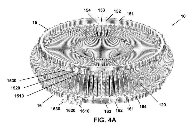
5 Now turning to Figures 4A-40, the conductive components 10 (which from
now on will be
simply referred to as the "stator 10") are shown without the stator housing 20
or the flux
guides 30, in the form of lamination packs. As is best appreciated from the
top-down view
of Figure 40, the stator 10 has distributed windings and comprises a plurality
(in this case
sixteen) of circumferentially distributed stator poles 11a, 11b, ..., 11p,
each of which
10 comprises a plurality of conductive coils 12. Each conductive coil 12 is
connected to one
phase of a multi-phase power supply via connection means 15, 16 which in this
example
take the form of busbars. In this specific example, the stator 10 is
configured for use with a
three-phase power supply so there are three conductive coils 12 per pole 11a-
11p of the
stator.
15 It will be appreciated that with sixteen poles 11a-11p and three
conductive coils 12 per
pole, the stator 10 of Figures 4A-C has a total of 48 circumferentially
distributed conductive
coils 12. However, it can be seen from the top-down view of Figure 40 that
this stator 10
actually has 96 radially extending active sections. Further, it can be seen
from the side-on
view of Figure 4B that there are two axially offset layers of radially
extending active
sections, giving a total of 192 radially extending active sections. The
reasons for this will
become apparent from the description of Figures 5-9. In summary, each
conductive coil 12
includes one or more conductive elements 120, each of which includes a pair of
axially
offset radially extending active sections. Each conductive coil 12 of the
stator 10 of Figures
4A-4B includes two such conductive elements 120, and since each conductive
element 120
includes a pair of axially offset radially extending sections, the total of
192 radially
extending active sections is accounted for.
The conductive components of stator 10 may be made of any combination of one
or more
conductive materials. However, the conductive components 10 are preferably
made from
copper.
Figures 5A-5D are various views of a single conductive element 120. As noted
above and
as will be explained in more detail below, each conductive coil 12 is made up
of one or
more conductive elements 120. It will be appreciated that in the case of one
conductive
element 120 per conductive coil 12, a conductive coil 12 and a conductive
element 120 are
CA 03128290 2021-07-29
WO 2020/157503 PCT/GB2020/050213
16
equivalent. Figures 6A-6D illustrate a conductive coil 12 which is made up of
two
conductive elements 120 and 120', and will be described below.
Returning to Figures 5A-5D, as is best appreciated from the top-down views of
Figure 5A in
which the axis of rotation is perpendicular to the plane of the page, a
conductive element
120 includes a pair of circumferentially pitched apart, radially extending
active conducting
sections 121a, 121b. These radially extending active sections 121a, 121b are
referred to as
"active" sections because, when the conductive coils 12 are positioned in the
stator, they
are disposed within the stator core and so interact with the magnetic field
provided by the
magnets of the rotors 2a, 2b. It will be appreciated that since the active
sections extend in a
generally radial direction, which is approximately perpendicular to the axial
flux in the core,
the flux linkage is at least close to maximized.
The angle y by which the two active sections 121a, 121b are pitched apart will
be referred
to as the coil span. The coil span can be the same as or different (less or
more) than the
pole pitch a (defined by the angle between the centres of the permanent
magnets of the
rotor). Preferably the coil span y is less than the pole pitch a. For example,
y may be
approximately 5/6 of a. By making y less than a, short-chording of the winding
can be
implemented, which reduces the spatial harmonic content of the winding
magnetomotive
force (mmf).
Turning to Figures 5E and 5F, these show a sixteen-pole, three-phase stator
10' which is
similar to the stator 10 of Figures 4A-40, but differs in that each coil 12 of
stator 10' has
only one conductive element 120 (one pair of active sections 121a, 121b). That
is, in
Figures 5E and 5F, a coil 12 and a conductive element 120 are equivalent. Like
stator 10,
conductive coils 120a, 120b, 120c of stator 10' are circumferentially
distributed around the
stator and circumferentially adjacent coils circumferentially overlap.
As is particularly clear from Figure 5E, the circumferential overlap of the
coils 120a, 120b,
120c defines circumferential spaces between active sections of the coils.
These
circumferential spaces, which are elongated in the radial direction, can
receive flux guides
30. Spaces such as the labelled spaces 141a, 141b, 141c will be referred to as
spaces of
the first type. As can be seen, spaces of the first type 141a, 141b, 141c are
defined
between active sections of different coils. For example, space 141b is between
one of the
two active sections of coil 120a and one of two active sections of coil 120c.
However, it is
to be appreciated that the two coils that define a particular space of the
first type 141a,
CA 03128290 2021-07-29
WO 2020/157503 PCT/GB2020/050213
17
141b, 141c can depend on various factors, including the number of phases per
stator pole,
the number of poles and the selected coil span y.
Now returning to Figures 5A-5D, as can be seen from Figures 5B and 5D, the two
active
sections 121a, 121b are axially offset from each other. This facilitates
stacking of the
conductive coils 12 in the circumferential direction, and also facilitates the
circumferential
stacking of conductive elements 120 where there are multiple conductive
elements 120 per
conductive coil 12. As will be discussed in more detail with reference to
Figure 14, this
allows for more stator poles and more slots per pole per phase, both of which
can provide
for greater efficiency. Furthermore, the winding may be readily short chorded.
As can be seen in each of Figures 5B, 50 and 5D, each conductive element 120
is formed
from a continuous length of wound conductor. The outermost winding of the
length of
conductor terminates at a first connection portion 128, which will be referred
to as the outer
tail 128. The outer tail 128 extends substantially parallel to the axial
direction. As will be
described in more detail below, this facilitates convenient connection of the
coils 12 to the
multi-phase power supply. The innermost winding turn portion terminates at a
second
connection portion 129, which will be referred to as the inner tail 129.
As can also be seen in each of Figures 5B, 5C and 5D, the length of conductor
that forms
the conductive element 120 is wound such that there are a plurality of winding
turn portions
131a, 131b stacked parallel to the axis of rotation of the electrical machine.
The resulting
cross-section of the conductive element 120 that is perpendicular to the
radial direction of
each active section 121a, 121b is elongate with a major dimension parallel to
the axis of
rotation. In the example of Figures 5A-5D, there are fourteen axially stacked
winding turn
portions 131a, 131b, though this is not intended to limit the invention as
other numbers are
equally possible.
Figures 5G, 5H and 51 illustrate how the conductive element 120 may be formed
by winding
a length of conductor. As illustrated in Figure 5G, the conductor is wound
around a pair of
support elements 301, 302 (which protrude perpendicularly out of the plane of
page) in a
single plane so as to form a flat, planar winding with a number (in this case
fourteen) of
turns or layers. That the winding is flat is best appreciated from Figures 5H
and 51. The
innermost winding terminates at the inner tail 129 and the outermost winding
terminates at
the outer tail 128.
CA 03128290 2021-07-29
WO 2020/157503
PCT/GB2020/050213
18
Having formed the flat winding shown in Figures 5G-5I, the three-dimensional
shape of the
conductive element 120 is formed by bending or deforming the flat winding into
the shape
shown in Figures 5A-5D. The bending can be performed using a bending tool, as
is known
in the art. For example, a bending tool with axially offset inner male profile
blocks may push
against outer female forms to bend the flat winding so that the active
sections are axially
offset from each other. The outer tail 128 and inner tail 129 may be
separately bent as
desired.
To make the bending process easier, the flat winding may first be imparted
with additional
strength so that the winding maintains its shape during the bending. In one
example, the
conductor has a heat- or solvent-activated outer bond layer so that after
winding, the
turns/layers can be bonded together to maintain the shape.
It should be appreciated, particularly from Figures 5G-5I, that the conductive
element 120
can be wound in a variety of different ways, and the particular winding that
is illustrated is
not intended to limit the invention. Some alternatives include:
- While the winding in Figure 5G has been wound around the support elements
301,
302 in an anti-clockwise sense, the length of conductor could equally be wound
in
the clockwise sense.
- While the outermost turn of the winding terminates such that that
outer tail 128
leads into an active section 121a, 121b of the conductive element 120, this
need
not be the case. The outer turn could terminate at any point of the turn, for
example
so that the outer tail 128 leads into a loop section of the turn rather than
an active
section.
- While fourteen axially stacked winding turns are illustrated in Figure 5,
there could
be more than or fewer than fourteen turns.
-
While the winding is one turn/layer thick (see Figure 5H in particular), it
could be
more than one turn/layer thick. In this case, each conductive element 120 will
comprise a plurality of circumferentially stacked winding turn portions. While
any
number of circumferentially stacked winding turn portions is possible, the
number
will preferably be less than the number of winding turn portions in the axial
direction,
such that the cross-section of the conductive element 120 that is
perpendicular to
the radial direction of each active section 121a, 121b still has a major
dimension
CA 03128290 2021-07-29
WO 2020/157503 PCT/GB2020/050213
19
that is parallel to the axis of rotation. For example, the ratio of the number
of axially
stacked turns to the number of circumferentially stacked turns may be greater
than
three, and may preferably be greater than five.
As will be appreciated from the above, in use, current will flow along the two
active sections
121a, 121b of the conductive element 120 in opposite directions (that is,
inward and
outward parallel to the radially extending direction). The reversal of the
current direction is
provided by outer loop sections 122 of the winding turn portions 131a, 131b
and by inner
loop sections 125 of the winding turn portions 131a, 131b. Each of the outer
loop sections
122 includes a first portion 123 and a pair of second portions 124a, 124b (one
for each of
the pair of active sections 121a, 121b) which connect the active sections
121a, 121b to the
first portion 123. Similarly, each of the inner loop sections 125 includes a
first portion 126
and a pair of second portions 127a, 127b (one for each of the pair of active
sections 121a,
121b) which connect the active sections 121a, 121b to the first portion 126.
As can be seen from Figures 5B, 5C and 5D, the outer first portions 123
together form an
outer part 133 of the coil element 120 with a surface that is substantially
parallel to the axis
of rotation. In the specific example of Figures 5A-5D, the outer first
portions 123 are
substantially semi-circular and so the outer part 133 is a substantially flat
half-disk 133, but
other shapes are possible. For example, each of the outer first portions 123
may have a
shape corresponding to three sides of a rectangle, such that they together
form an outer
part 133 which has a flat rectangular surface. As another example, the outer
part 133 of the
conductive element 120 formed by the outer first portions 123 need not be flat
or planar:
this is illustrated in Figure 5J, which shows a conductive element 120" with
an outer part
133" with a curved profile and therefore curved surface. Figure 5K illustrates
a plan view of
a stator 10" comprising such conductive elements, which can be compared to
Figure 40
(though note that stator 10" does not show any connecting means 15, 16).
The surface 133 formed by the outer first portions 123 can be used to
facilitate cooling due
to its relatively large surface area. Further, since the outer part 133 of the
coil 120 is
substantially parallel to the axis is rotation, a stator housing 20 may be
provided with axially
extending apertures 25 which axially receive the outer part 133 of the coil
element 120',
120" to provide mechanical locking and improved cooling. This will be
explained in more
detail below.
The inner first portions 126 together form an inner part 136 of the coil
element 120. The
inner part 136 illustrated in Figures 5B-5D is substantially the same as the
outer part 133
CA 03128290 2021-07-29
WO 2020/157503 PCT/GB2020/050213
described above, and like the outer part 133 described above may be parallel
to the axis of
rotation and may be of various shapes and profiles. However, the inner part
136 will
generally play less of a role in cooling and stacking of the coils 12, and so
the inner
portions 126 may be configured so as to reduce the overall quantity of
conductor per
5 conductive element 120 to reduce costs.
With regards to the outer second portions 124a, 124b and the inner second
portions 127a,
127b, while they appear substantially straight in Figures 5A-5D, they are in
fact slightly
curved. Specifically, the shape of each of the outer first portions 124a, 124b
is a section of
a first involute, and so the first portions 124a, 124b together form outer
substantially
10 involute parts 134a, 134b of the coil element 120. Similarly, the shape
of each of the inner
second portions 127a, 127b is a section of a second involute, and so the first
portions
127a, 127b together form inner substantially involute parts 137a, 137b of the
coil element
120. The significance of the involutes will be described with reference to
Figures 6A-6D.
While it has been described above that the conductive element 120 is formed by
winding a
15 length of conductor, this is not essential. The conductive element 120
could be
manufactured in other ways, including by being formed integrally.
Further, while the illustrated elements 120 are wound from a length of
conductor and
comprise a stack of winding turn portions 131a, 131b, this is preferred but
not essential.
For example, rather than axially extending stack of winding turn portions
131a, 131b, each
20 conductive element 120 could be formed by a single axially extending
conductive strip. In
some cases a single axially extending conductive strip may be preferable to a
plurality of
axially stacked winding turn portions 131a, 131b but, as will be described
below, the use of
stacked winding turn portions 131a, 131b advantageously helps mitigate the
skin and
proximity effects which can otherwise lead to increased losses.
As noted above, each conductive coil 12 may include only one conductive
element 120.
However, for reasons which will be explained in more detail below, each
conductive
element preferably includes two or more circumferentially overlapping
conductive elements.
An example of a conductive coil that includes two circumferentially
overlapping conductive
elements 120, 120' will now be described with reference to Figures 6A-6D.
Figure 6A shows above and below views of a conductive coil 12 which includes
two
conductive elements 120, 120'. The features of each of the two conductive
elements 120,
CA 03128290 2021-07-29
WO 2020/157503 PCT/GB2020/050213
21
120' are the same as those of the single conductive element 120 described
above with
reference to Figures 5A-5D, and so their features will not be described again.
To form the conductive coil 12, two identical conductive elements 120, 120'
are electrically
connected together in series at their inner tails 129, 129'. In the examples
illustrated herein,
the inner tails 129, 129' are connected using a ferrule 130. However, there
are other ways
of connecting the inner tails 129, 129', such as brazing or welding. To
connect the two
elements 120, 120', one of the two conductive elements 120, 120' is rotated
180 about the
axis running vertically in the plane of the page in Figure 6A so that the
outer tails 128, 128'
of the two conductive elements 120, 120' are in opposite directions and the
inner tails 129,
129' are adjacent and therefore readily connected by a ferrule 130.
Alternatively, the
conductive coil 12 comprising two conductive elements could be integrally
formed as a
single piece.
The resulting conductive coil 12 has two pairs of circumferentially
overlapping, pitched
apart pairs of active sections 121a, 121b; 121a', 121b'. Notably, the overlap
of the two
pairs of active sections defines two spaces 142a, 142b. The first space 142a
is defined
between one (a first) active section 121a of a first of the conductive
elements 120 of the
coil 12 and between one (a first) active section 121a' of the second of the
conductive
elements 120' of the coil 12. The second space 142b is defined between the
other (the
second) active section 121b of the first conductive element 120 of the coil 12
and between
the other (the second) active section 121b' of the second conductive element
120' of the
coil 12. That is, the two spaces 142a, 142b are circumferential spaces between
adjacent
active sections 121a, 121a'; 121b, 121b' of two different pairs of active
sections 121a,
121b; 121a', 121b' of the same coil 12. Spaces of this type will be referred
to as spaces of
the second type. Like the spaces of the first type, spaces of the second type
142a, 142b
provide spaces for flux guides 30, such as lamination packs. This makes it
easier to
construct the stator assembly 1, and also increases the number of slots per
pole per phase
of the stator assembly 1, which can increase the motor's efficiency.
Having now described spaces 141a-c of the first type (that is, spaces defined
between
active sections of different coils) and spaces 142a-b of the second type (that
is, spaces
defined between active sections of the same coil but different pairs), it is
noted that when a
plurality of coils 12 which define spaces of the second type are provided in a
stator 10 so
as to define spaces of the first type, the spaces of the first and second
types may coincide.
This can be seen most clearly in Figure 11A, which illustrates a sixteen-pole,
three-phase
stator in which each coil 12 comprises two conductive elements 120, 120'. Only
half of the
CA 03128290 2021-07-29
WO 2020/157503 PCT/GB2020/050213
22
conductive coils 12 are shown in Figures 11A-B so that the spaces can be
clearly seen.
Whether spaces of the first and second type coincide may depend on a number of
factors,
including the selected coil span y, the number of stator poles and the number
of phases.
Returning to Figures 6A-6D, it can also be seen from Figures 6A and 6B that
there is a gap
143a between the second portions 124a, 124a' of the outer loop sections 122,
122' which
form one pair of outer involute parts 134a, 134a' of the two conductive
elements 120, 120'.
Likewise, there is a gap 143b between the second portions 124b, 124b' of the
outer loop
sections 122, 122' which form the other pair of outer involute parts 134b,
134b'. There is
also a gap 144a between the second portions 127a, 127a' of the inner loop
sections 125,
125' which form one pair of inner involute parts 137a, 137a'. Finally, there
is also a gap
144b between the second portions 127b, 127b' of the inner loop sections 125,
125' which
form the other pair of outer involute parts 137b, 137b'. Due to the geometric
properties of
involutes, the width of these gaps 143a, 143b, 144a, 144b remains
substantially constant
along the length of the involute sections of the conductive elements 120,
120'. This
advantageously reduces the resulting diameter of the motor for a given rating
and losses in
the coils.
While a conductive coil 12 with two conductive elements 120, 120' has been
described, it
should be appreciated that a conductive coil 12 could have any integer number
of
conductive elements 120, including more than two. Increasing the number of
conductive
elements per conductive coil 12 will increase the number of spaces of the
second type
defined by the circumferentially adjacent active sections of the conductive
elements 120,
which in turn increases the number of slots per pole per phase in the stator
1. This can lead
to the generation of a stator magnetic field with a more accurately sinusoidal
magnetic flux
density, with less significant harmonic distortion. This advantageously
reduces the
.. development of eddy currents in the permanent magnets of the rotors 2a, 2b,
which in turn
reduces heating losses and therefore provides a higher motor efficiency.
However, it will be
appreciated that the number of conductive elements 120 per conductive coil 12
will
generally be limited by size constraints. For example, for a given cross-
section of
conductor (that is, the cross-section of the wire from which the windings are
wound) and a
.. given radius of the stator, the number of conductors which can be
circumferentially fit into a
single coil span y is limited.
If a coil 12 is to have more than two conductive elements, there may be
several further
considerations. For example:
CA 03128290 2021-07-29
WO 2020/157503 PCT/GB2020/050213
23
If the coils are to be formed by connecting multiple conductive elements 120
(by ferrules 130, for example), it may be preferable to provide several types
of
conductive elements to facilitate simpler connection of adjacent conductive
elements. For instance, the conductive elements 120 described above may be
used
for the two circumferentially outer conductive elements, since their outer
tails 128
will be connected to the power-supply. However, the one or more inner
conductive
elements that are between the outer conductive elements will be connected to
conductive elements at both their inner tails 129 and outer tails 128, so a
second
type of conductive element with outer tails 128 adapted in a similar fashion
to the
inner tails 129 may be provided for ease of connection. Alternatively, each
coil 12
may be formed as an integral unit, rather than by the connection of three or
more
separate conductive elements.
Integer multiples of two conductive elements 120 per coil 12 may be
preferable to an odd number of conductive elements 120 per coil 12. If an
integer
multiple of two elements 120 are used, the outer tails 128 of the two
circumferentially outermost elements 120 will be directed in opposite parallel
directions, as in Figure 6A-6D. While this is not essential, it provides for a
more
straightforward connection of the coils 12 using the connection means which
will be
described below with reference to Figures 7-10.
While a stator 10 with a single axial layer of circumferentially distributed
coils 12 (the single
layer having coils 12 with axially offset active sections) has been described,
it will be
appreciated that there may be multiple axially-stacked layers of coils per
stator. In this
case, the spaces of the first type and/or the spaces of the second type of
each layer may
advantageously substantially circumferentially coincide. This would
advantageously allow
for the insertion of axially-longer flux guides 30 which could extend through
the axial length
of the multiple axially-stacked layers, providing further gains in terms of
ease and speed of
assembly.
Connecting the Coils to a Multi-Phase Power Supply
Ways of connecting a plurality of circumferentially distributed conductive
coils 12 to a multi-
phase power supply will now be described. It should be appreciated that in
practice there
are many different ways which this could be accomplished, and many different
ways will
occur to one skilled in the art. The invention is therefore not limited to any
particular
connection arrangement. However, the described ways of connecting the
conductive coils
CA 03128290 2021-07-29
WO 2020/157503 PCT/GB2020/050213
24
12, which utilize connection means 15, 16 which are provided axially
above/below a plane
that is perpendicular to the axis of rotation and axially above/below the
conductive coils,
provides a particularly neat and well-organized set of connections. Further,
the connections
are easy to make, which reduces the likelihood of a poor connection, and the
stator may be
resin impregnated without impregnating the connection means, which allows
connections
to be checked and fixed even after impregnation of the stator assembly.
First referring to Figure 4B, there is a first connection means 15 that is
provided axially
above a plane that is perpendicular to the axis of rotation of the motor 100
and that is
axially above the conductive coils 12. There is also a second connection means
16 that is
provided axially below a plane that is perpendicular to the axis of rotation
of the motor 100
and that is axially below the conductive coils 12. In the case of the stator
10, which is
configured for use with a 3-phase power supply, the connection means 15 and 16
include
provision for each of the 3-phases. However, this could be extended to a multi-
phase
power supply with any number of phases.
In the particular connection arrangement of Figures 4A-40, which will be
referred to as a
parallel connection arrangement, each of the connection means 15, 16 includes
three
phase-connections and one star-connection. That is, the first connection means
15
includes a first phase connection 151 for a first phase of the power supply, a
second phase
connection 152 for a second phase of the power supply, a third phase
connection 153 for a
third phase of the power supply, and a star connection 154. Similarly, the
second
connection means 16 includes a first phase connection 161 for the first phase
of the power
supply, a second phase connection 162 for the second phase of the power
supply, a third
phase connection 163 for the third phase of the power supply, and a star
connection 164.
In the described examples, the phase connections 151-153, 161-163 and star
connections
154, 164 are in the form of annular busbars whose outer circumference (though
equally this
could be the inner circumference) substantially coincides with the axially
extending outer
tails 128, 128' of the conductive coils. The phase connection busbars 151-153,
161-163 are
themselves connected to the power supply via inputs 1510-1530, 1610-1630.
In the illustrated parallel connection arrangement, each conductive coil 12 is
connected to
one phase of the power supply by connecting the coil 12 to one of the phase
connections
of one of the connection means 15, 16 (as an example, phase connection 151)
and to the
star connection of the other of the connection means 15, 16 (in the example,
star
connection 164). The connection of one conductive coil 12 to one phase
connection 151
CA 03128290 2021-07-29
WO 2020/157503 PCT/GB2020/050213
and one star ring 164 is illustrated in and will now be described with
reference to Figures
7A-7C.
Figures 7A-70 show one conductive coil 12 that has two conductive elements
120, 120'
connected to a first phase connection 151 from the first connection means 15,
and to the
5 star connection 164 from the second connection means 16. Since the outer
tails 128, 128'
of the conductive coil 12 extend axially and in opposite directions, and since
the
circumference of the busbars 151, 164 coincides with the axial extending outer
tails 128,
128', the outer tails 128, 128' are easily connected to the connections 151,
164.
In order to make the connection even easier, the annular busbars 151, 164 are
provided
10 with circumferentially spaced apart receiving means 151a-h, 164a-x for
receiving the axially
extending outer tails 128, 128' of the coils 12. In the 3-phase parallel
connection
arrangement shown, each star connection 154, 164 will be connected to half of
all coils 12,
whereas each phase connection 151-153, 161-163 will only be connected to one
in six
coils 12. Consequently, in this example, the star connection 164 has three
times as many
15 equally spaced receiving means 164a-x than the first phase connection
151.
Returning to Figures 4A-4C, each pole 11a-11p of the stator 10 consists of one
conductive
coil 12 for each phase (Le. three conductive coils 12 per pole ha-p because
the stator is
configured for use with a 3-phase supply), and circumferentially adjacent
conductive coils
12 are connected to different phases. This is illustrated in Figures 11A and
11B for a
20 sixteen pole stator 10 which is connected to a 3-phase power supply but
for which only half
of the conductors are shown, and so has only 24 circumferentially distributed
conductive
coils 12 can be seen.
In view of this, in the 3-phase parallel connection arrangement illustrated in
Figures 4, 7-9
and 11-12, every sixth conductive coil 12 will be connected to the connection
means 15, 16
25 in the same way. This is illustrated in Figures 8A and 8B. It can be
that there are eight
equally spaced conductive coils 12a-g connected to the same phase connection
151 and
the same star ring 164. Although not shown in Figures 8A-8B, it will be
appreciated that
half way between each of the coils will be another coil 12 connected to the
same phase of
the power-supply, but by the complimentary set of bus bars. That is, to the
phase
connection 161 and the star connection 154.
The conductive coils 12 corresponding to the other phases of the power-supply
will be
connected in essentially the same way as described above for one phase. To
illustrate this,
CA 03128290 2021-07-29
WO 2020/157503 PCT/GB2020/050213
26
Figures 9A-90 show how two circumferentially adjacent conductive coils 12 are
connected
in the parallel connection arrangement.
Figures 9A-90 show two circumferentially adjacent conductive coils 12a, 12b.
Conductive
coil 12a is connected in a similar way as conductive coil 12 in Figures 7A-7C.
That is, coil
12a is connected to the second phase connection 152 and the star connection
164. Coil
12b, being circumferentially adjacent to coil 12a, is connected to a different
phase of the
power supply and is therefore connected to a different pair of busbars.
Specifically, but
without loss of generality, circumferentially adjacent coil 12b is connected
to the third phase
connection 163 of the second connection means 16 and to the star connection
154 of the
first connection means.
The connections of the conductive coils 12 have been described above with
reference to a
parallel connection arrangement. However, other connection arrangements are
possible.
To illustrate this, Figure 10 shows an alternative arrangement, which will be
referred to as a
series connection arrangement.
In the series connection arrangement of Figure 10, the first connection means
15' which is
above the conductive coils 12 differs from the connection means 15 of Figures
4, 7-9 and
11-12 in that it does not include a star connection: it only includes a first
phase connection
151', a second phase connection 152' and a third phase connection 153'.
However, the
second connection means 16' is the same as the second connection means 16 of
Figures
4, 7-9 and 11-12 in that it has three phase connections 161', 162', 163' and a
star
connection 164'. To compensate for the lack of star connection in the first
connection
means 15', the conductive coils 12 are connected in a different way. The phase
connections 151'-153' of the first connection means 15' also serve twice as
many
conductive coils 12, and therefore have additional receiving means compared to
the
receiving means of the second connection means 16' and the first and second
connection
means 15, 16 of the parallel connection arrangement.
Figure 10 illustrates the series connection arrangement for two
circumferentially adjacent
stator poles 11 and 11'. Like the parallel connection arrangement, each pole
11, 11'
includes one conductive coil per pole, giving three coils per pole: pole 11
consists of
conductive coils 12a, 12b and 12c, and pole 11' consists of conductive coils
12a', 12b' and
12c'. Also like with the parallel connection arrangement, circumferentially
adjacent coils are
connected to different phases. However, while the coils of the same phase but
adjacent
poles (12a and 12a', for example) in the parallel connection arrangement are
essentially
CA 03128290 2021-07-29
WO 2020/157503 PCT/GB2020/050213
27
independently connected and form separate current paths, in the series
connection
arrangement their connections are related and they are part of the same
current path.
Considering only coils 12a, 12a' which are connected to the same phase, the
coil 12a of
the first pole 11 is connected by its outer tails to the phase connection 153'
of the first
connection means and to the phase connection 163' of the second connection
means. The
coil 12a' of the second, adjacent pole 11' is connected to the phase
connection 153' of the
first connection means 15' and to the star connection 164' of the second
connection
means. The current path can therefore be considered to run from the phase
connection
163' through the coil 12a, then along phase connection 153' and then through
coil 12a' to
the star connection 164'.
Different connection arrangements may be used for different practical
applications. For
example, the series connection arrangement described above theoretically
provides a
machine Torque Constant (measured in Nm/A) that is twice as high as than that
provided
by the parallel connection arrangement described above. This will be better
for some,
though certainly not all, practical applications.
While the connection means 15, 15' have been described as being above the
coils 12 and
the connection means 16, 16' have been described as being below the coils, it
should be
appreciated that both pairs 15, 16; 15', 16' may be above the coils or both
pairs 15, 16; 15',
16' may be below the coils. In this case, it may be preferable to produce
coils 12 whose
outer tails 128, 128' extend in the same axial direction rather than opposite
axial directions.
Further, while the connection means 15, 16, 15' and 16' have been described as
continuous, annular busbars, this is merely one way of implementing the
connection
means. For example, the connection means may not be continuous or annular, and
may
instead take the form of a series of two or more circumferentially distributed
busbar
sections. Many other kinds of connection means will occur to those skilled in
the art.
Stator Manufacture
The features and construction of the conductive coils 12 described above
provide for
particularly efficient and effective manufacture of a stator that includes a
plurality of
circumferentially distributed coils 12. Of particular significance is the fact
that the coils 12
themselves provide a structure into which flux guides 30, for example in the
form of
lamination packs, can be provided. This makes placing of the flux guides 30 in
the stator
CA 03128290 2021-07-29
WO 2020/157503 PCT/GB2020/050213
28
assembly 1 a comparatively straightforward and precise exercise, especially
compared to
many known manufacturing techniques which may involve winding coils around
bobbin-like
structures which house lamination packs, and then separately securing (using
glue, for
example) the wound bobbin-like structures into a stator housing. Various other
advantages
will be described.
Figure 13 is a flow-chart illustrating a method 500 for manufacturing a
stator.
The method 500 includes providing 510 a plurality of conductive coils, such as
the
conductive coils 12 described above. Preferably the conductive coils 12 have a
plurality of
circumferentially overlapping pairs of circumferentially pitched apart
radially extending
active sections (as in the coil 12 of Figures 6A-6D) such that each coil 12
provides spaces
of the second type. However, the coils 12 may only have one pitched apart pair
of active
sections (as in the coil of Figures 5A-5D). The conductive coils 12 may have
been formed
as a single integral piece, by connecting multiple conductive elements 120 in
series, or in
any other way.
At 520, the method 500 includes positioning a plurality of the conductive
coils 12 in a stator
housing so that the plurality of coils are circumferentially distributed
around the stator
housing. Preferably the conductive coils are positioned so that
circumferentially adjacent
conductive coils circumferentially overlap and thereby define spaces of the
first type for
receiving flux guides. The circumferential overlap of circumferentially
adjacent coils 12 can
be ensured by providing an appropriate number of coils 12 of an appropriate
coil span y
within the housing. As noted above, where the coils 12 have multiple pairs of
active
sections such that the coils each define spaces of the second type, the spaces
of the first
and second types may coincide with each other.
The stator housing 20 may be provided with a plurality of circumferentially
spaced apart
axially extending apertures 25 for receiving the coils 12. This makes the
positioning of the
coils 12 in the stator housing easier and more precise. Advantageously, if the
coils 12 are
formed so as to have an axially extending outer part 133, the axially
extending outer part
133 can be received within the axially extending apertures 25. Since the
axially extending
outer part 133 have a large surface area, they provide good mechanically
locking of the
coils 12 in the stator housing for assembly without the need for glue (for
example) and also
provide a source of cooling of the stator. Circumferentially distributed
apertures 25 for
receiving the coils 12 can most clearly be seen in Figures 12A-120.
CA 03128290 2021-07-29
WO 2020/157503 PCT/GB2020/050213
29
Optionally, at 530, the method 500 includes positioning flux guides 30, such
as lamination
packs, in the spaces (of the first and/or second type) defined by the coils
12. As explained
above, the overlap of adjacent coils creates spaces of the first type 141a,
141b, 141c
between active sections of different coils. If the coils 12 each comprise more
than one pair
of radially extending active sections (as in Figures 6A-6D), pairs of spaces
142a, 142a' of
the second type will also be defined within each conductive coil 12. In either
case, flux
guides can also be positioned within the spaces. Since the coils 12 themselves
provide a
structure with defined spaces, positioning the lamination packs into the
structure is
straightforward, fast and precise. In combination with the provision of
apertures 25 in the
stator housing 20 for receiving the coils 12, this means that both the
components of the
stator core (the active sections of the coils 12 and the flux guides 30) can
be quickly and
very accurately positioned compared to many known techniques. It will be
appreciated that
accurately positioned core components reduces losses and therefore improves
machine
efficiency.
Optionally, at 540, the method 500 includes connecting the plurality of coils
12 to
connecting means 15, 16 so that the coils can be connected to the multi-phase
power
supply. This may be done in any desired way, for example as described above
using
busbars in the parallel or series connection arrangements.
Optionally, at 550, the method 500 includes impregnating at least part of the
stator
assembly 1 in a bonding compound such as a resin. This strengthens the stator
structure
and therefore protects the stator assembly 1 against the electromagnet and
mechanical
forces it experiences in use. Furthermore, it can improve the conduction of
heat between
the stator constituents if the bonding compound has a heat transfer
coefficient significantly
higher than air.
If the connecting means 15, 16 are provided axially above and/or below the
coils 12 as
described above, the impregnation of the stator can take place before or after
the coils are
connected to the connecting means. Further, and advantageously, if the
connecting means
15, 16 themselves are not impregnated, the connections can be tested, altered,
and if
necessary replaced after impregnation. This is highly desirable because a
faulty connection
in a resin-impregnated stator may otherwise render the entire stator unusable
and
unfixable.
Machine Efficiency
CA 03128290 2021-07-29
WO 2020/157503 PCT/GB2020/050213
Axial flux machines 100 comprising the stator assembly 1 described herein have
been
found to provide not only a high peak efficiency, but a high efficiency over a
broad range of
operating parameters. While high peak efficiencies are often quoted, they are
in practice
rarely achieved, especially in applications where the machine is required to
perform over a
5 range of operating parameters. Efficiency over a broad range of
parameters is therefore a
more practically meaningful measure for many applications.
To illustrate this, Figure 14 is an efficiency map showing the measured
efficiency of an
axial flux machine comprising the stator assembly of Figures 12A-120 for a
range of torque
and speed values that are commonly-used in many applications. Contours of
constant
10 efficiency are included on the efficiency map. As can be seen, as well
as a high peak
efficiency (93%), the efficiency remains very high for almost all of the area
of the efficiency
map and high (over 80%) even at a relatively low speed of 500 rpm up to a
torque of
30 Nm.
There may be a number of different reasons for the high efficiencies which the
stator
15 assembly 1 is able to achieve. Some of these will now be described.
First, as explained above, the almost self-forming structure of the conductive
components
of the stator 10 that is provided by the geometry of the coils 12 allows for
the very accurate
placement of components of the stator core. The accurate placement of the
components of
the core means that there is better coupling of the stator and rotor fields,
and a high degree
20 of symmetry around the circumference of the stator which improves the
generation or
torque.
Another significant advantage is the generation of a stator field with a more
accurately
sinusoidal magnetic flux density. As will be understood by those skilled in
the art, the higher
the number of slots per pole per phase in the stator, the more sinusoidal the
magnetic flux
25 density can be. The coils 12 and stator 10 described above can provide
an increased
number of slots per pole per phase by increasing the number of conductive
elements 120
per conductive coil 12, and this number can easily be scaled up (if, for
example, the radius
of the stator can be increased for a particular application). An advantage of
a highly
sinusoidal magnetic flux density is that the flux density has a relatively low
harmonic
30 content. VVith a low harmonic content, more of the coupling the rotor
and stator fields
involves the fundamental components of the flux density, and less involves the
interaction
with the harmonic components. This reduces the generation of eddy currents in
the rotor
magnets, which in turn reduced losses due to heating. In contrast, many known
axial flux
CA 03128290 2021-07-29
WO 2020/157503 PCT/GB2020/050213
31
motors utilize a concentrated winding arrangement which only provides for a
limited
number (e.g. fractional) slot per pole per phase, which generates a much more
trapezoidal
flux density with more significant harmonic components.
While the coils 12 can be implemented using axially extending strips, they are
preferably
implemented using axially stacked winding arrangement illustrated in Figures
5A-5D and
6A-6D. While many motor manufacturers may consider this a disadvantage because
it may
be considered to reduce the fill factor in the stator core, the inventors have
found this
disadvantage is compensated for by the reduction in the skin and proximity
effects which
causes currents to flow around the outside of the conductor cross-section and
predominantly the axially-outer portions of the active sections. The number of
windings in
the axial direction may be selected to balance these two considerations.
Described above are a number of embodiments with various optional features. It
should be
appreciated that, with the exception of any mutually exclusive features, any
combination of
one or more of the optional features are possible.