Note: Descriptions are shown in the official language in which they were submitted.
CA 03128501 2021-07-30
WO 2020/163237 PCT/US2020/016422
ACCESS NEEDLE SYSTEMS AND METHODS
CROSS-REFERENCE TO RELATED APPLICATIONS
[0001] The present disclosure is related to, and claims priority under the
rules and regulations of
the WIPO Patent Cooperation Treaty to US Provisional Patent Application No.
62/800,894
entitled ACCESS NEEDLE SYSTEMS AND METHODS to Toufic Kachaamy, filed on
February 4, 2019, the content of which is herein incorporated by reference in
their entirety, for
all purposes.
TECHNICAL FIELD
[0002] The present description relates in general to medical devices, and more
particularly to,
for example and without limitation, access needles and methods and uses
thereof.
BACKGROUND OF THE DISCLOSURE
[0003] An estimated 1,230,000 endoscopic retrograde cholangiopancreatography
("ERCP")
procedures were performed in the 28 member countries of the European Union and
the United
States in 2016. As part of an ERCP procedure, cannulation must first be
achieved in order to gain
access to the desired duct(s); however, this can sometimes be challenging. One
approach is to
use a sphincterotome device (also called a papillotome), inserted through a
working channel of a
duodenoscope. A sphincterotome is a catheter that contains an electrosurgical
cutting wire at the
distal end, which is used to perform sphincterotomies (e.g., cutting of
sphincter muscles in order
to gain duct access to perform follow-up procedures). However, in some
scenarios, ERCP can
fail due to cannulation failure, even using a sphincterotome in some cases,
and/or due to inability
to access the papilla.
[0004] The description provided in the background section should not be
assumed to be prior art
merely because it is mentioned in or associated with the background section.
The background
section may include information that describes one or more aspects of the
subject technology.
SUMMARY
[0005] In one embodiment, an access needle is provided that includes a needle
housing and a
needle shaft having a portion disposed within the needle housing. The needle
also includes a
lumen within the needle shaft, an entry port at a proximal end of the needle
shaft, and a needle tip
at a distal end of the needle shaft. The needle also includes an exit port on
a sidewall of the needle
- 1 -
CA 03128501 2021-07-30
WO 2020/163237 PCT/US2020/016422
shaft, wherein the exit port is disposed nearer the distal end of the needle
shaft than the proximal
end, and wherein the lumen extends from the entry port to the exit port.
[0006] In a second embodiment, a method is provided that includes placing a
needle in a vicinity
of an organ, the organ comprising a target portion. The needle comprises: a
needle housing, a
needle shaft, a lumen within the needle shaft, an entry port at a proximal end
of the needle shaft,
a needle tip at a distal end of the needle shaft, and an exit port on a
sidewall of the needle shaft.
The method also includes piercing the organ with the needle tip, and injecting
a contrast medium
into the organ through the lumen in the needle shaft. The method also includes
adjusting a
position of the needle in the organ based on an image of the organ, the image
comprising the
contrast agent, so that the exit port points to the target portion, and
inserting a wire through the
entry port, the lumen, and the exit port, to access the target portion.
[0007] In yet other embodiment, a system, a system is provided that includes
an access needle
to direct a guiding element to a target portion of an organ, the access needle
including a needle
housing and a needle shaft having a portion disposed within the needle
housing. The access
needle further includes a lumen within the needle shaft, an entry port at a
proximal end of the
needle shaft and a needle tip at a distal end of the needle shaft. The access
needle also includes
an exit port on a sidewall of the needle shaft, wherein the exit port is
disposed nearer the distal
end of the needle shaft than the proximal end, and wherein the lumen extends
from the entry port
to the exit port. The system also includes an imaging device to direct the
access needle in a
vicinity of the organ and puncture an access site in the organ with the needle
tip. The imaging
device further includes a radiation source configured to direct a radiation to
the organ, and a
radiation detector configured to detect a scattered radiation from the organ.
The imaging device
also includes a controller, configured to receive a signal from the radiation
detector and convert
the signal into an image and a display, configured to display the image from
the controller to
direct the needle in the vicinity of the organ.
BRIEF DESCRIPTION OF THE DRAWINGS
[0008] FIG. 1 illustrates a diagram of a biliary tree structure.
[0009] FIG. 2 illustrates a diagram of a part of an access needle, in
accordance with various
aspects of the subject disclosure.
[0010] FIG. 3 illustrates an enlarged cross-sectional view of a distal end of
a needle shaft of the
access needle of FIG. 2, in accordance with various aspects of the subject
disclosure.
- 2 -
CA 03128501 2021-07-30
WO 2020/163237 PCT/US2020/016422
[0011] FIG. 4 illustrates an enlarged cross-sectional view of a distal end of
a needle shaft of the
access needle of FIG. 2 with a wire disposed in a lumen of the shaft, in
accordance with various
aspects of the subject disclosure.
[0012] FIG. 5 illustrates an enlarged cross-sectional view of a portion of a
needle shaft of the
access needle of FIG. 2 in the vicinity of a lock, in accordance with various
aspects of the subject
disclosure.
[0013] FIG. 6 illustrates an enlarged cross-sectional view of a distal end of
a needle shaft of the
access needle of FIG. 2 disposed within a bile duct, in accordance with
various aspects of the
subject disclosure.
[0014] FIG. 7 illustrates an enlarged cross-sectional view of a distal end of
a needle shaft of the
access needle of FIG. 2 disposed within a bile duct and rotated with respect
to the orientation
shown in FIG. 6, in accordance with various aspects of the subject disclosure.
[0015] FIG. 8 illustrates a diagram of an access needle having a sheath, in
accordance with
various aspects of the subject disclosure.
[0016] FIG. 9 illustrates a portion of the access needle of FIG. 8, including
a tapered portion of
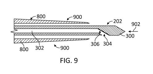
the sheath, in accordance with various aspects of the subject disclosure.
[0017] FIG. 10 illustrates an electrocautery enhanced access needle to deliver
a cautery current
to treat bleeding along an access site, in accordance with various aspects of
the subject disclosure.
[0018] FIG. 11 illustrates an access needle including a rotatable mechanism to
guide a wire to a
target portion in an organ, in accordance with various aspects of the subject
disclosure.
[0019] FIG. 12 illustrates an access needle accessing a target portion of an
organ during surgery
of a patient, in accordance with various aspects of the subject disclosure.
[0020] FIG. 13 is a flowchart illustrating steps in a method for accessing a
target portion of an
organ during surgery of a patient, in accordance to various embodiments.
[0021] In one or more implementations, not all of the depicted components in
each figure may
be required, and one or more implementations may include additional components
not shown in
a figure. Variations in the arrangement and type of the components may be made
without
departing from the scope of the subject disclosure. Additional components,
different components,
or fewer components may be utilized within the scope of the subject
disclosure.
- 3 -
CA 03128501 2021-07-30
WO 2020/163237 PCT/US2020/016422
DETAILED DESCRIPTION
[0022] The detailed description set forth below is intended as a description
of various
implementations and is not intended to represent the only implementations in
which the subject
technology may be practiced. As those skilled in the art would realize, the
described
implementations may be modified in various different ways, all without
departing from the scope
of the present disclosure. Accordingly, the drawings and description are to be
regarded as
illustrative in nature and not restrictive.
[0023] Access of a duct or cavity with endoscopic ultrasound (EUS) has become
more common,
such as for bile duct drainage when ERCP fails or is not possible. This often
requires access of
the duct or cavity with a needle under EUS guidance, and then passing a wire
to allow for further
passage of other tools over the wire into the cavity. This technique can be
used for gallbladder
access and drainage when patients have a gallbladder infection and surgery is
not desired, and for
drainage of fluids around the gastrointestinal track such as drainage of
collections around the
pancreas or the rectum.
[0024] Currently endoscopic ultrasound-guided (EUS-guided) biliary access is
considered a
rescue technique when endoscopic retrograde cholangiography (ERCP) fails due
to cannulation
failure or the inability to access the papilla. Endoscopic ultrasound-guided
biliary access,
however, is very technically challenging. One of the reasons for the
technically challenging
nature of this procedure is the lack of dedicated tools, specifically tools
that facilitate biliary
access and allow manipulation of a wire in a desired direction, either to
perform rendezvous (e. g. ,
in which the wire is passed down the papilla and then captured to be used to
facilitate standard
ERCP), or to advance the wire toward the liver and perform direct stenting of
the bile duct.
[0025] Access needles for biliary access are disclosed herein. Access needles
are also used to
access the gallbladder, and abscesses and collections next to the
gastrointestinal tract, in addition
to uses for pancreatic cyst and pancreatic duct access. Some access needles
include a 19-gauge
access needle making them stiff and difficult to manipulate and advance into
the bile duct.
Moreover, these access needles typically include an opening for wire access at
the tip of the
needle. An opening for wire access at the tip of the needle creates a risk of
wire shearing by the
tip. The risk of wire shearing can be reduced by providing a pointed cutting
tip on a stylet that is
removed once the access is achieved, allowing insertion and manipulation of
the wire. However,
even with the reduced risk of shearing provided by a stylet, access needles
with the wire opening
- 4 -
CA 03128501 2021-07-30
WO 2020/163237 PCT/US2020/016422
at the tip do not allow easy guidance of the wire direction, and some risk of
shearing may still
remain.
[0026] The common biliary duct splits into left and right hepatic ducts, and
an exemplary access
needle of the present disclosure may help with accessing these ducts more
easily. In some
procedures, high obstruction of the biliary tree may require the placement of
two guidewires. An
example embodiment of the present disclosure allows two or more wires to be
placed in selected
dilated ducts for faster access, thus shortening the procedure. In some
embodiments of the present
disclosure, an exemplary access needle makes the placement of two wires easier
to perform, by
allowing rotation of the location of a wire access port on a side of the
needle.
[0027] In accordance with aspects of the subject disclosure, an improved
access needle is
provided. The improved access needle may be smaller than currently available
needles and can
vary in size (e.g., between about 25-gauge and about 18-gauge, such as about
22-gauge), so as to
be easier to manipulate and advance into the bile duct.
[0028] The needle includes an internal lumen that extends between a wire entry
port at a
proximal end and a wire exit port on a sidewall of the needle. The lumen may
include guide
features that guide the wire from the lumen to the exit port along a curve
that is not sharp. In this
way, the wire exit port does not cause shearing of the wire, forms a wide exit
at an angle at a
location that is not from the tip of the needle, and facilitates rotation of
the direction of exit of the
wire from the port. For example, the needle can be rotatable within and/or by
a needle housing
to rotate the location of the wire exit port. In this way, the disclosed
access needle allows the
wire to be manipulated to exit in any desired direction. The needle shaft that
includes the lumen
may be formed from a flexible material, and includes a tip shaped to
facilitate advancing the
needle and cutting through tough tissue such as the bile duct.
[0029] Accordingly, embodiments of the present disclosure may achieve
advantages such as
wire access to the bile duct for patients with challenging ductal anatomies.
[0030] FIG. 1 illustrates a portion of the duodenum 2 at the location of a
sphincter 4 (i.e.,
sphincter of Oddi) at the major duodenal papilla. The biliary duct 6 and
pancreatic duct 8 are also
shown in FIG. 1.
[0031] FIG. 2 illustrates a side view of an example access needle 200 that may
be used to access,
for example, biliary duct 6 (e.g., for insertion of a wire such as a guide
wire). Access needle 200
includes a needle housing 204 in which a needle shaft 202 is disposed. A wire
entry port 201 is
an opening to allow entering of the wire at the proximal end of needle housing
204. Needle shaft
- 5 -
CA 03128501 2021-07-30
WO 2020/163237 PCT/US2020/016422
202 may be fixedly disposed in needle housing 204 such that needle shaft 202
can be advanced
and/or rotated by advancing and/or rotating the housing through a rotatable
handle 206. For
example, the needle shaft may be fixed to the housing by a locking mechanism
212 or can be
permanently fixed to the housing. Alternatively, the needle shaft may be
moveably disposed in
the needle housing such that the needle shaft can be advanced and/or rotated
with respect to the
housing. As shown in FIG. 2, access needle 200 may also include an entry port
201 at a proximal
end 208 of the needle shaft, a handle 206 on the needle housing 204 (e.g., for
rotating and
advancing the needle), a lock 210 for locking the needle shaft 202 to an
endoscope channel, and
locking mechanism 212. Locking mechanism 212 may be used for locking the
needle shaft in
place relative to the needle housing 204 and/or locking the needle shaft 202
to another object.
[0032] FIG. 3 shows an enlarged cross-sectional view of the distal end of
needle shaft 202. As
shown in FIG. 3, needle shaft 202 includes a needle tip 300 at a distal end of
the needle shaft, and
a lumen 302 within the needle shaft. An exit port 304 is also shown on a
sidewall of the needle
shaft 202, nearer the distal end of the needle shaft than the proximal end.
Exit port 304 enables
the wire to leave the needle shaft 202 and access the biliary duct or other
organ portion. In various
examples, needle shaft 202 has a gauge of between about 25 and about 18 (e.g.,
about twenty-two
or higher). FIG. 3 also shows how needle shaft 202 may include a guide surface
306 that is gently
curved and thus configured to guide a wire from the lumen 302 through the exit
port 304. In
accordance to various embodiments, guide surface 306 may have a smooth texture
to decrease
the risk of shearing, stopping, or jerking the wire as it passes through and
is bent onto exit port
304. For example, in some embodiments, the system may include a stylet
configured to cover
guide surface 306 and make it smooth.
[0033] FIG. 4 illustrates an arrangement in which a wire 400 is disposed
within lumen 302, and
in which distal portion 402 of wire 400 has been guided by guide surface 306
from the lumen out
of the side of needle shaft 202 via exit port 304, proximal to needle tip 300.
In various scenarios,
a second wire may also be fed through the lumen 302, e.g., through a second
entry port at the
proximal end of the needle shaft to receive the second wire.
[0034] FIG. 5 illustrates a further enlarged cross-sectional view of a portion
of needle shaft 202
forming lumen 302 in the vicinity of lock 210.
[0035] FIG. 6 illustrates an arrangement in which the tip 300 of needle shaft
202 has pierced an
organ 600 (e.g., duct 6 of FIG. 1 in a dilated state) above a target portion
(e.g., an obstruction
602), and in which wire 400 has been inserted into the bile duct in the
direction of the obstruction
- 6 -
CA 03128501 2021-07-30
WO 2020/163237 PCT/US2020/016422
via exit port 304 in the side of needle shaft 202. Because needle shaft 202
(or a portion thereof
such as the distal portion) is rotatable, the exit port 304 can be positioned
and oriented such that
distal portion 402 of wire 400 exits the needle in the desired direction.
[0036] To achieve the arrangement shown in FIG. 6, needle shaft 202 may be
advanced until tip
300 pierces the bile duct 600. The bile duct may then be aspirated and/or
injected with contrast
media, such as a contrast dye, through the needle to verify the location of
the needle. Needle
shaft 202 and exit port 304 in the sidewall of the needle shaft may then be
rotated to a desired
location and/or orientation. A wire such as wire 400 may then be inserted via
entry port 201,
through lumen 302 and out through exit port 304. Needle housing 204 and handle
206 are also
illustrated, for perspective.
[0037] FIG. 7 illustrates an example in which exit port 304 has been rotated
such that distal
portion 402 of wire 400 exits in the opposite direction from that shown in
FIG. 6. Exit port 304
can be rotated by rotating the distal portion of needle shaft 202, by rotating
the entirety of needle
shaft 202, and/or by rotating housing 204 with handle 206. Also illustrated
are entry port 201,
lumen 302, and organ 600.
[0038] FIG. 8 shows a side view of access needle 200 in an alternative
implementation in which
a sheath 800 is formed around at least a portion of needle shaft 202. Sheath
800 may be formed
from plastic, metal, or other biocompatible materials and can be softer and/or
more flexible than
the metal of needle shaft 202. In the example of FIG. 8, sheath 800 is
positioned such that at least
some of the sheath 800 is disposed between the needle housing 204 and the
needle shaft 202.
[0039] In this example, handle 206 for rotation of the position of exit port
304 is disposed on a
proximal side of needle housing 204. In this example, locking mechanism 212 is
also disposed
on the proximal side of needle housing 204 and is configured to lock the
needle shaft 202 in
position relative to the sheath 800. For example, when locking mechanism 212
locks needle shaft
202 in position relative to sheath 800, handle 206 can be manipulated to
rotate sheath 800 within,
or along with, needle housing 204 to rotate needle shaft 202 and consequently
exit port 304.
When locking mechanism 212 is unlocked, needle shaft 202 may be rotatable
and/or slidable
within sheath 800. In this example, lock 210 may lock access needle 200 to an
endoscope such
that needle shaft 202 remains movable (e.g., slidable) with respect to the tip
of the endoscope
within or along with sheath 800.
[0040] In one arrangement, access needle 200 is configured to allow adjustment
of the position
of the needle shaft 202 relative to the sheath 800 and to allow advancement of
the sheath 800 over
- 7 -
CA 03128501 2021-07-30
WO 2020/163237 PCT/US2020/016422
the needle shaft 202 if desired, allowing duct and cavity access via the
sheath 800. In the example
of FIG. 8, needle 200 is shown in side view, with the distal portion of sheath
800 shown in cross-
section for clarity. As indicated in FIG. 8, needle 200 may include features
803 for controlling
the position and movement of needle shaft 202 relative to the sheath 800.
[0041] In the example of FIG. 8, at least one of the needle housing 204, the
sheath 800, or the
needle shaft 202 is rotatable (e.g., together or separately) for modification
of an exit direction of
a wire in the lumen 302 from the exit port 304 by rotation of the exit port.
In this example, the
needle shaft 202 may be slidably disposed within the sheath 800 (e.g., when
locking mechanism
212 is unlocked). In the example of FIG. 8, a removable cover 802 is provided
for the entry port
201 near proximal end 208. Cover 802 may also be configured to removably cover
entry port
201 of FIG. 2. In the examples of FIGS. 2 and 8, entry port 201 is configured
to receive a wire
for passage of the wire through the lumen 302 and the exit port 304. Entry
port 201 may also
include an attachment feature (not explicitly shown) for attachment of a
syringe to provide fluid
into the lumen 302 to the exit port 304. In implementations in which sheath
800 is provided, the
sheath may have a tapered distal end.
[0042] FIG. 9 shows a portion of the access needle of FIG. 8 in an example in
which sheath 800
includes a tapered portion 900. In this example, sheath 800 has a proximal end
(not shown in
FIG. 9) and a distal end, and the distal end includes the tapered portion 900,
which tapers toward
the cutting tip 300 of the needle shaft 202. In this example, the sheath 800
is tapered at the distal
end to, for example, allow advancing of sheath 800 over the needle shaft 202
(e.g., by movement
of needle shaft 202 relative to sheath 800 parallel to direction 902) into the
cavity or duct to be
used as an access device if the needle shaft 202 is removed. In one
operational scenario, a first
wire can be inserted into the duct via lumen 302 in needle shaft 202, sheath
800 can be advanced
over the needle shaft into the duct, needle shaft 202 can be removed, and a
larger wire can be fed
into the duct along the first wire through the relatively wider lumen of the
sheath. Guide surface
306 bends the wire and directs it towards exit port 304.
[0043] It is understood that the specific order or hierarchy of steps,
operations, or processes
disclosed is an illustration of exemplary approaches. Unless explicitly stated
otherwise, it is
understood that the specific order or hierarchy of steps, operations, or
processes may be performed
in different order. Some of the steps, operations, or processes may be
performed simultaneously.
The accompanying method claims, if any, present elements of the various steps,
operations, or
processes in a sample order, and are not meant to be limited to the specific
order or hierarchy
presented. These may be performed in serial, linearly, in parallel, or in
different order.
- 8 -
CA 03128501 2021-07-30
WO 2020/163237 PCT/US2020/016422
[0044] FIG. 10 illustrates an electrocautery enhanced access needle 1000 to
deliver a cautery
current to treat bleeding along an access site, in accordance with various
aspects of the subject
disclosure. A handle 1006 may be used to adjust (e.g., rotate, pitch, and
roll) the position of
electrocautery enhanced needle 1000 inside an organ and to point exit port
1004 in a desired
direction (e.g., a target portion of the organ).
[0045] A port 1001 in handle 1006 receives an electric current and transmits
the electric current
to tip 1010. In some embodiments, tip 1010 includes an electrically conductive
material while
the rest of the shaft is shielded from electricity. Tip 1010 thus delivers the
current into the
surrounding tissue in the organ. In some embodiments, the current acts as a
cautery current to
treat bleeding along the access site of the organ (e.g., the point at which
the tip has punctured the
organ) by allowing blood coagulation through heat. In some embodiments, the
current acts as a
cutting element to dilate the access site of the organ and facilitate
insertion of other devices in the
organ, through the enlarged access site. Electrocautery enhanced access needle
1000 also
includes a guiding surface 1306f to guide a wire or any other guiding
component through lumen
1002 out of exit port 1004 (e.g., guiding surface 306, lumen 202, and exit
port 304). In some
embodiments, the electrocautery tip is on the shaft of the needle and can be
used to treat bleeding
or to allow advancement of the shaft over a wire or the needle into the tissue
or duct.
[0046] FIG. 11 illustrates an access needle 1101 including a rotatable
mechanism to guide a wire
to a target portion in an organ, in accordance with various aspects of the
subject disclosure.
Access needle 1101 is housed longitudinally (along the axis of the channel)
inside a sheath 1112
(e.g., outer catheter). Access needle 1101 is coupled with an inner handle
1106a. Inner handle
1106a is housed inside an outer handle 1106b. Outer handle 1106b may be
coupled with a biopsy
channel 1150 via an anchoring mechanism 1115 (e.g., screw on, for fixation to
a scope ¨not shown
in the figure-). Inner handle 1106a rotates inside from and relative to, outer
handle 1106b, about
a common longitudinal axis. Rotation of inner handle 1106a leads to rotation
of access needle
1101 including needle tip 1100, needle shaft 1102, and exit port 1104. The
rotation gives the
ability to guide the direction of a wire towards the target portion of the
organ (e.g., liver or
duodenum). Note that, according to some embodiments, while needle shaft 1102
rotates about a
longitudinal axis, sheath 1112 remains stationary, thus reducing friction with
exterior tissue or
other endoscopic components.
[0047] FIG. 12 illustrates an access needle 1200 accessing a target portion
602 (e.g., bile duct
obstruction, and the like) of an organ 600 during surgery of a patient 1201,
in accordance with
various aspects of the subject disclosure. In some embodiments, an imaging
system 1260 may be
- 9 -
CA 03128501 2021-07-30
WO 2020/163237 PCT/US2020/016422
used as an aid tool during surgery. Imaging system may include a radiation
source 1250 (e.g., an
ultrasound source, a light source, an X-ray source, and the like) emitting a
radiation that is
scattered from at least a portion of organ 600 and collected by a radiation
detector 1251 (e.g., an
ultrasound detector, a light detector, an X-ray detector, and the like).
Imaging system 1260 reads
a signal from radiation detector 1251 and generates an image of the surgical
area in display 1261.
To do these operations, imaging system 1260 includes a controller 1262 that
performs analog and
digital electronic data analysis on the signal provided by radiation detector
1251. In the image,
the surgeon or nurse may have an augmented and clear view of access needle
1200, organ 600,
and target portion 602. Accordingly, the surgeon or nurse may assess the
relative position and
orientation of exit port 1214 and target portion 602. Thus, the surgeon or
nurse may actuate a
handle 1206 to adjust the position of access needle 1200 in organ 600.
[0048] In some embodiments, access needle 1200 may include one or more markers
1230-1,
1230-2, 1230-3, and 1230-4 (hereinafter, collectively referred to as "markers
1230") disposed
adjacent to at least one of the needle tip, exit port 1214, a needle housing
1204, a needle shaft
1202, or handle 1206. In some embodiments, markers 1230 are configured to
scatter an
ultrasound radiation, an electromagnetic radiation, or any other type of
radiation or combination
thereof. In some embodiments, markers 1230 may be detectable with radiation
detector 1251.
[0049] FIG. 13 is a flowchart illustrating steps in a method 1300 for
accessing a target portion
of an organ during surgery of a patient using an imaging system (e.g., target
portion 602 in organ
600 of patient 1201 and imaging system 1260, cf. FIG. 12), in accordance to
various
embodiments. Methods and systems consistent with the present disclosure may
include at least
one or more of the steps in method 1300 performed in the same or different
order. For example,
in some embodiments, a method consistent with the present disclosure may
include one or more
of the steps in method 1300 performed simultaneously, quasi-simultaneously, or
overlapping in
time.
[0050] Step 1302 includes placing a needle in a vicinity of the organ, the
organ including the
target portion (e.g., electrocautery enhanced access needle 1000, and access
needle 1200, cf.
FIGS. 1-11). The needle includes a needle housing, a needle shaft, a lumen
within the needle
shaft, an entry port at a proximal end of the needle shaft, a needle tip at a
distal end of the needle
shaft, and an exit port on a sidewall of the needle shaft (e.g., housing 204,
cutting tip 300, needle
shaft 202, handle 206, locking mechanism 212, entry port 201, exit port 304,
lumen 302, and wire
400, cf. FIGS. 1-10).
- 10 -
CA 03128501 2021-07-30
WO 2020/163237 PCT/US2020/016422
[0051] Step 1304 includes piercing the organ with the needle tip. In some
embodiments, step
1304 includes directing an electric current through the tip into an access
point in the organ to
dilate the access point in the organ.
[0052] Step 1306 includes injecting a contrast medium into the organ through
the lumen in the
needle shaft.
[0053] Step 1308 includes adjusting a position of the needle in the organ
based on an image of
the organ, the image including the contrast agent, so that the exit port
points to the target portion.
In some embodiments, step 1308 includes rotating the needle housing along a
longitudinal axis
in the needle shaft. In some embodiments, step 1308 includes directing a
radiation to the organ
and collecting a scattered radiation from the organ with an imaging system.
[0054] Step 1310 includes inserting a wire through the entry port, the lumen,
and the exit port,
to access the target portion. In some embodiments, step 1310 includes removing
the needle
housing and the needle shaft and guiding a medical device through the wire, to
the target portion.
In some embodiments, the target portion is an obstructed duct, and step 1310
includes removing
the needle housing and the needle shaft and guiding a stent through the wire
to the obstructed
duct. In some embodiments, step 1310 includes directing an electric current
through the needle
tip into an access point in the organ, to cauterize a bleeding or create a
path for passing larger
devices or instruments.
[0055] A reference to an element in the singular is not intended to mean one
and only one unless
specifically so stated, but rather one or more. For example, "a" module may
refer to one or more
modules. An element proceeded by "a," "an," "the," or "said" does not, without
further
constraints, preclude the existence of additional same elements.
[0056] Headings and subheadings, if any, are used for convenience only and do
not limit the
invention. The word exemplary is used to mean serving as an example or
illustration. To the
extent that the term include, have, or the like is used, such term is intended
to be inclusive in a
manner similar to the term comprise, as comprise is interpreted when employed
as a transitional
word in a claim. Relational terms such as first and second and the like may be
used to distinguish
one entity or action from another without necessarily requiring or implying
any actual such
relationship or order between such entities or actions.
[0057] Phrases such as an aspect, the aspect, another aspect, some aspects,
one or more aspects,
an implementation, the implementation, another implementation, some
implementations, one or
more implementations, an embodiment, the embodiment, another embodiment, some
- 11-
CA 03128501 2021-07-30
WO 2020/163237 PCT/US2020/016422
embodiments, one or more embodiments, a configuration, the configuration,
another
configuration, some configurations, one or more configurations, the subject
technology, the
disclosure, the present disclosure, other variations thereof and alike are for
convenience and do
not imply that a disclosure relating to such phrase(s) is essential to the
subject technology or that
such disclosure applies to all configurations of the subject technology. A
disclosure relating to
such phrase(s) may apply to all configurations, or one or more configurations.
A disclosure
relating to such phrase(s) may provide one or more examples. A phrase such as
an aspect or some
aspects may refer to one or more aspects and vice versa, and this applies
similarly to other
foregoing phrases.
[0058] A phrase "at least one of' preceding a series of items, with the terms
"and" or "or" to
separate any of the items, modifies the list as a whole, rather than each
member of the list. The
phrase "at least one of' does not require selection of at least one item;
rather, the phrase allows a
meaning that includes at least one of any one of the items, and/or at least
one of any combination
of the items, and/or at least one of each of the items. By way of example,
each of the phrases "at
least one of A, B, and C" or "at least one of A, B, or C" refers to only A,
only B, or only C; any
combination of A, B, and C; and/or at least one of each of A, B, and C.
[0059] In one aspect, a term coupled or the like may refer to being directly
coupled. In another
aspect, a term coupled or the like may refer to being indirectly coupled.
[0060] Terms such as top, bottom, front, rear, side, horizontal, vertical,
distal, proximal, and the
like refer to an arbitrary frame of reference, rather than to the ordinary
gravitational frame of
reference. Thus, such a term may extend upwardly, downwardly, diagonally, or
horizontally in a
gravitational frame of reference.
[0061] The disclosure is provided to enable any person skilled in the art to
practice the various
aspects described herein. In some instances, well-known structures and
components are shown
in block diagram form in order to avoid obscuring the concepts of the subject
technology. The
disclosure provides various examples of the subject technology, and the
subject technology is not
limited to these examples. Various modifications to these aspects will be
readily apparent to those
skilled in the art, and the principles described herein may be applied to
other aspects.
[0062] All structural and functional equivalents to the elements of the
various aspects described
throughout the disclosure that are known or later come to be known to those of
ordinary skill in
the art are expressly incorporated herein by reference and are intended to be
encompassed by the
claims. Moreover, nothing disclosed herein is intended to be dedicated to the
public regardless
- 12 -
CA 03128501 2021-07-30
WO 2020/163237 PCT/US2020/016422
of whether such disclosure is explicitly recited in the claims. No claim
element is to be construed
under the provisions of 35 U.S.C. 112, sixth paragraph, unless the element is
expressly recited
using the phrase "means for" or, in the case of a method claim, the element is
recited using the
phrase "step for."
RECITATION OF EMBODIMENTS
[0063] Embodiments disclosed herein include:
[0064] I. An access needle including a needle housing is provided. The
access needle
includes a needle shaft having a portion disposed within the needle housing, a
lumen within the
needle shaft, and an entry port at a proximal end of the needle shaft. The
access needle also
includes a needle tip at a distal end of the needle shaft, and an exit port on
a sidewall of the needle
shaft, wherein the exit port is disposed nearer the distal end of the needle
shaft than the proximal
end, and wherein the lumen extends from the entry port to the exit port.
[0065] II. A method for placing a needle in a vicinity of an organ, the
organ including a target
portion, is provided. The needle includes: a needle housing, a needle shaft, a
lumen within the
needle shaft, an entry port at a proximal end of the needle shaft, a needle
tip at a distal end of the
needle shaft, and an exit port on a sidewall of the needle shaft. The method
includes piercing the
organ with the needle tip, injecting a contrast medium into the organ through
the lumen in the
needle shaft, adjusting a position of the needle in the organ based on an
image of the organ, the
image including the contrast agent, so that the exit port points to the target
portion, and inserting
a wire through the entry port, the lumen, and the exit port, to access the
target portion.
[0066] III. A system including an access needle to direct a guiding element
to a target portion
of an organ is provided. The access needle includes a needle housing, a needle
shaft having a
portion disposed within the needle housing, a lumen within the needle shaft,
and an entry port at
a proximal end of the needle shaft. The access needle also includes a needle
tip at a distal end of
the needle shaft, and an exit port on a sidewall of the needle shaft, wherein
the exit port is disposed
nearer the distal end of the needle shaft than the proximal end, and wherein
the lumen extends
from the entry port to the exit port. The system includes an imaging device to
direct the access
needle in a vicinity of the organ and puncture an access site in the organ
with the needle tip. The
imaging device includes a radiation source configured to direct a radiation to
the organ, a radiation
detector configured to detect a scattered radiation from the organ, a
controller, configured to
receive a signal from the radiation detector and convert the signal into an
image, and a display,
configured to display the image from the controller to direct the needle in
the vicinity of the organ.
- 13 -
CA 03128501 2021-07-30
WO 2020/163237 PCT/US2020/016422
[0067] Additionally to embodiments I, II, and III, embodiments consistent with
the present
disclosure may include any one or more of the following elements, in any
combination.
[0068] Element 1, wherein the needle shaft has a gauge of about twenty-five or
higher. Element
2, further including a guide surface configured to guide a wire from the lumen
through the exit
port. Element 3, further including a wire in the lumen. Element 4, further
including a second
wire in the lumen, and a second entry port at the proximal end of the needle
shaft to receive the
second wire. Element 5, further including a locking mechanism. Element 6,
further including a
lock for attaching the needle shaft to an endoscope channel of an endoscope.
Element 7, wherein
the needle shaft is adjustable within the needle housing to allow movement of
the needle shaft
relative to a tip of the endoscope. Element 8, wherein at least one of the
needle housing, the
needle shaft, or the distal end of the needle shaft is rotatable for
modification of an exit direction
of a wire from the exit port, by rotation of the exit port. Element 9, further
including a sheath
disposed around the needle shaft. Element 10, further including a locking
mechanism configured
to lock the needle shaft in position relative to the sheath. Element 11,
wherein at least one of the
needle housing, the sheath, the needle shaft, or the distal end of the needle
shaft is rotatable for
modification of an exit direction of a wire from the exit port, by rotation of
the exit port. Element
12, wherein the needle shaft is slidably disposed within the sheath. Element
13, wherein the
sheath has a proximal end and a distal end, and wherein the distal end tapers
toward the needle
tip of the needle shaft. Element 14, further including a removable cover for
the entry port.
Element 15, wherein the entry port is configured to receive a wire for passage
of the wire through
the lumen and the exit port. Element 16, wherein the entry port further
includes an attachment
feature for attachment of a syringe to provide fluid into the lumen to the
exit port. Element 17,
wherein the lumen forms a guiding surface to bend the wire to the exit port
within the needle
shaft. Element 18, further including one or more markers disposed adjacent to
at least one of the
needle tip or the exit port, the one or more markers being detectable with an
ultrasound radiation
or an electromagnetic radiation. Element 19, further including one or more
markers disposed
adjacent to at least one of the needle housing, the needle shaft, or a needle
handle, the one or more
markers configured to scatter an ultrasound radiation or an electromagnetic
radiation.
[0069] Element 20, wherein piercing the organ with the needle tip further
includes directing an
electric current through the needle tip into an access point in the organ to
dilate the access point
in the organ. Element 21, wherein adjusting the position of the needle in the
organ includes
rotating the needle housing about a longitudinal axis in the needle shaft.
Element 22, wherein
adjusting the position of the needle in the organ includes directing a
radiation to the organ and
- 14 -
CA 03128501 2021-07-30
WO 2020/163237 PCT/US2020/016422
collecting a scattered radiation from the organ with an imaging system.
Element 23, further
including removing the needle housing and the needle shaft and guiding a
medical device through
the wire, to the target portion. Element 24, wherein the target portion is an
obstructed duct, further
including: removing the needle housing and the needle shaft; and guiding a
stent through the wire
to the obstructed duct. Element 25, further including directing an electric
current through the
needle tip into an access point in the organ, to cauterize a bleeding. Element
26, wherein adjusting
a position of the needle in the organ based on an image of the organ includes
receiving an
ultrasound radiation or an electromagnetic radiation scattered from one or
more markers disposed
adjacent to at least one of the needle tip or the exit port, and including an
image of the needle in
the image of the organ using the ultrasound radiation or the electromagnetic
radiation. Element
27, wherein adjusting a position of the needle in the organ based on an image
of the organ includes
receiving an ultrasound radiation or an electromagnetic radiation scattered
from one or more
markers disposed adjacent to at least one of the needle housing, the needle
shaft, or a needle
handle, and including an image of the needle in the image of the organ based
on the ultrasound
radiation or the electromagnetic radiation.
[0070] Element 28, wherein the needle shaft has a gauge of about twenty-five
or higher. Element
29, further including a guide surface configured to guide a wire from the
lumen through the exit
port. Element 30, further including a wire in the lumen. Element 31, further
including a locking
mechanism. Element 32, further including a lock for attaching the needle shaft
to an endoscope
channel of an endoscope, wherein the needle shaft is adjustable within the
needle housing to allow
movement of the needle shaft relative to a tip of the endoscope. Element 33,
wherein at least one
of the needle housing, the needle shaft, or the distal end of the needle shaft
is rotatable for
modification of an exit direction of a wire from the exit port, by rotation of
the exit port. Element
34, further including a sheath disposed around the needle shaft, and a locking
mechanism
configured to lock the needle shaft in position relative to the sheath,
wherein at least one of the
needle housing, the sheath, the needle shaft, or the distal end of the needle
shaft is rotatable for
modification of an exit direction of a wire from the exit port, by rotation of
the exit port, wherein
the needle shaft is slidably disposed within the sheath, and wherein the
sheath has a proximal end
and a distal end, and wherein the distal end tapers toward the needle tip of
the needle shaft.
Element 35, further including a removable cover for the entry port. Element
36, wherein the entry
port is configured to receive a wire for passage of the wire through the lumen
and the exit port,
wherein the entry port further includes an attachment feature for attachment
of a syringe to
provide fluid into the lumen to the exit port, and wherein the lumen forms a
guiding surface to
- 15 -
CA 03128501 2021-07-30
WO 2020/163237 PCT/US2020/016422
bend the wire to the exit port within the needle shaft. Element 37, wherein
the access needle
further includes one or more markers disposed adjacent to at least one of the
needle tip, the exit
port, the needle housing, the needle shaft, or a needle handle, the one or
more markers configured
to scatter an ultrasound radiation or an electromagnetic radiation generated
by the radiation
source.
[0071] The title, background, brief description of the drawings, and drawings
are hereby
incorporated into the disclosure and are provided as illustrative examples of
the disclosure, not as
restrictive descriptions. They are submitted with the understanding that they
will not be used to
limit the scope or meaning of the claims. In addition, in the detailed
description, it can be seen
that the description provides illustrative examples and the various features
are grouped together
in various implementations for the purpose of streamlining the disclosure. The
method of
disclosure is not to be interpreted as reflecting an intention that the
claimed subject matter requires
more features than are expressly recited in each claim. Rather, as the claims
reflect, inventive
subject matter lies in less than all features of a single disclosed
configuration or operation. The
claims are hereby incorporated into the detailed description, with each claim
standing on its own
as a separately claimed subject matter.
[0072] The claims are not intended to be limited to the aspects described
herein, but are to be
accorded the full scope consistent with the language of the claims and to
encompass all legal
equivalents. Notwithstanding, none of the claims are intended to embrace
subject matter that fails
to satisfy the requirements of the applicable patent law, nor should they be
interpreted in such a
way.
- 16-