Note: Descriptions are shown in the official language in which they were submitted.
CA 03128935 2021-08-04
- 1 -
SECONDARY COIL TOPOLOGY
DESCRIPTION
The invention relates to a coil apparatus for receiving an
alternating magnetic field, in particular for an inductive
charging system. The coil apparatus is also provided for a
secondary device of an inductive charging system for a
contact-free inductive energy transfer to transport means.
Vehicles powered by their own engine such as, for example,
motor vehicles, motorbikes and locomotives are to be
understood by the term "transport means" in the following.
Such vehicles can be rail-bound or not rail-bound. The engine
can include an internal combustion engine, an electric motor
or a combination of the two, e.g. in the form of a hybrid
drive.
The term "inductive charging system" is understood as a
system for a contact-free energy transfer by means of
alternating magnetic fields. The system includes a primary
device (also called "primary system" or "primary element")
as the energy source and a secondary device (also called
"secondary system" or "secondary element") as an energy
receiver; similar to a transformer apparatus. The primary
device is designed to generate an alternating magnetic field.
The secondary device is designed to receive an or the
alternating magnetic field and to generate an induction
current from the alternating magnetic field. The generation
of the alternating magnetic field is achieved by means of an
alternating current flowing through electrical conductors,
in particular coils, of the primary device and the generation
of the induction current is achieved by means of electrical
conductors of the secondary device positioned in the magnetic
field.
WO 2016114893 describes an apparatus for wirelessly
Date Recue/Date Received 2021-08-04
CA 03128935 2021-08-04
- 2 -
transferring power and includes a first coil with a first
winding path and a second coil with a second winding path.
The apparatus comprises a holding device configured to hold
the first coil and the second coil in a predetermined winding
pattern. Each of the first and second winding paths comprises
a plurality of successive winding groups. In each of the
plurality of successive winding groups, at least a portion
of each winding of consecutive windings is arranged on top
of an immediately previous winding on the holding device for
a predetermined number of windings. The disclosed coil
arrangement can function either as a transmitter or as a
receiver.
Essentially, two different coil topologies are used for
electromagnetic induction. The first coil topology is a
circular coil, i.e. a coil with at least one turn around a
centre. The second coil topology is a bipolar coil (also
known as a double-D coil), which comprises a first coil with
one or more turns around a first centre and a second coil
with one or more turns around a second centre. The first
coil is electrically connected to the second coil in series
and wound in the opposite direction relative to the second
coil.
The prior art exhibits the drawback of only being designed
for a specific magnetic field pattern in which the coil
arrangement functions optimally and enables an optimal
energy transfer. In technical terms, such coil arrangements
have interoperability issues. This means that, for example,
a vehicle with a secondary coil from one manufacturer can
only be charged on a stationary apparatus with a primary
coil from another manufacturer with high losses
(interoperability).
For each magnetic field pattern generated, a specific
secondary coil topology is thus preferable in order to
achieve an optimal energy transfer from the at least one
Date Recue/Date Received 2021-08-04
CA 03128935 2021-08-04
- 3 -
primary coil to the at least one secondary coil.
In order to improve the interoperability of secondary coils,
additional receiving coils are currently being added, which
are respectively more suitable for receiving a corresponding
magnetic field pattern. However, such coil arrangements
exhibit the drawback of being heavy and costly.
It is thus the object of the present invention to provide an
improved coil apparatus for an inductive receiving system,
i.e. a secondary coil with a higher interoperability, which
simultaneously has a cost-effective and simple design.
To this end, the present invention provides a coil apparatus
according to claim 1. The latter is in particular configured
in such a manner that it comprises a first coil with a first
winding path A or a plurality of first turns and a second
coil with a second winding path B or a plurality of second
turns, wherein the first and the second coils are connected
to one another in series and are configured to run in
opposite directions relative to each other. This means in
particular that the two winding paths are configured in such
a manner that a current flowing through the two coils flows
clockwise in the first winding path and counterclockwise in
the second winding path or vice versa. Each winding has a
conductor/conductor section arranged internally and a
conductor/conductor section arranged externally, which are
arranged in particular parallel to each other. The coil
apparatus according to the invention is characterized in
that the internally and externally arranged conductors of at
least a portion of the first and second turns, respectively,
are arranged in such a manner that they respectively lie in,
i.e. span, a plane, wherein these planes diverge with respect
to each other in the direction from the first coil to the
second coil or vice versa, depending on whether the
conductors/conductor sections are conductors/ conductor
sections of the first turns or of the second turns.
Date Recue/Date Received 2021-08-04
CA 03128935 2021-08-04
- 4 -
It has been found in this connection that the coil apparatus
according to the invention has a higher interoperability
with different magnetic field patterns, of both circular and
bipolar coils. The coil apparatus is thereby more flexible
in terms of its range of application and can thus be used
with numerous different primary coils.
Another advantage is the improved, i.e. increased, alignment
offset of the coil apparatus. This means that the coil
apparatus does not have to be arranged centrally or at a
specific point vis-A-vis the primary coil in order to
constantly attain the best transfer efficiency. In other
words, the coil apparatus exhibits a smaller decrease in
transmission efficiency in comparison with the prior art
when it is offset from a predetermined point in relation to
the primary coil; the transfer efficiency remains almost
constant. An alignment of the coil apparatus is thus easier
while a constant energy transfer is more resistant to
positional deviations between the secondary and primary
coils.
In a preferred embodiment, the coil apparatus additionally
comprises a ferrite arrangement configured in such a manner
that it at least partially covers winding path sections
arranged centrally in the coil apparatus, i.e. the internally
arranged conductors of the first and second coils, on one
side, in particular on the side of an inductive transmitter
system or primary coil, and at least partially does not cover
or does not at all cover the remaining winding path sections
of the first and second coils on this side. The ferrite
arrangement facilitates a better magnetic field guidance and
thus a more effective energy transfer. This occurs in
particular by at least partially covering the centrally
arranged winding path sections, which is achieved by means
of at least one ferrite arrangement arranged on the
intermediate conductors and thus imitates a solenoid coil.
Date Recue/Date Received 2021-08-04
CA 03128935 2021-08-04
- 5 -
Preferably, at least 50% of the winding path sections are
covered, although there are also embodiments in which the
centrally arranged conductors are completely covered by one
or more ferrite arrangements. The ferrite arrangement can
also extend up to the two opposite, externally arranged
conductors of the first and second coils and thus, in
particular, at least partially cover the same.
In addition, the remaining winding path sections, i.e. all
conductor sections except the centrally or internally
arranged conductors, can also not be covered at all by the
ferrite arrangement; in particular on the side on which the
internally arranged winding path sections are covered.
The ferrite arrangement also has the advantage that it acts
as a holding device for the coils. The ferrite arrangement
thus performs several functions such as, e.g., magnetic field
guidance, especially stray field reduction, as well as the
positioning and holding of the coil conductors.
In an advantageous embodiment, the first and second coils
are respectively configured to be spiral-shaped, in
particular on at least one plane. In the process, the
diameter of the turns increases from one turn to the next in
the coil in question. This has the advantage of controlling
or reducing the height of the coil apparatus and in
particular of making it flat. The turns here can describe a
circular, square, rectangular or any other geometric shape.
In order to produce a particularly uniform design of the
coil apparatus, the internally arranged conductors/conductor
sections are arranged so as to be adjacent to one another
and in particular at least partially parallel to one another.
This design is uniform and efficient in its use of space. In
addition, interoperability with, e.g., circular coils is
improved.
Date Recue/Date Received 2021-08-04
CA 03128935 2021-08-04
- 6 -
Preferably, the distance between the directly adjacent
internally arranged conductors/conductor sections of the
first and second coils is greater than the distance between
the directly adjacent externally arranged
conductors/conductor sections of the first and second coils.
This has the advantage that the characteristics of a bipolar
coil do not predominate so that the coil apparatus is not
only geared to this design and a corresponding magnetic
field.
It has further proven advantageous when directly adjacent
laterally arranged conductors of the first and second coils
are arranged in pairs at least partially on top of one
another. This makes it possible to reduce the width of the
corresponding path sections and thus reduce the dimensions
or extension of the coil apparatus in width and length. In
particular, due to the ferrite arrangement according to the
invention, it is advantageous to arrange or stack the
conductors one on top of the other in the corresponding path
sections, as the use of space in terms of the height of the
coil apparatus is already set by the ferrite arrangement. It
is also possible to arrange three or more conductors on top
of one another, depending in particular on the height of the
ferrite arrangement and the diameter of the conductor.
Preferably, the ferrite arrangement comprises two
rectangular ferrite plate assemblies (or ferrite moulded
parts, or ferrite devices) arranged parallel to and spaced
apart from each other, wherein two supply conductors for the
two coils can extend between the ferrite plate assemblies.
This has the advantage of saving weight and simultaneously
providing space for the supply conductors. As the two ferrite
plate assemblies can be configured to be identical to one
another and can be symmetrically arranged in relation to the
coil apparatus, corresponding magnetic fields are not
adversely affected.
Date Recue/Date Received 2021-08-04
CA 03128935 2021-08-04
- 7 -
It has further proven advantageous when the ferrite plate
assemblies are formed from a plurality of identically shaped
or configured ferrite plates and/or from moulded parts with
a certain magnetic permeability. Besides known ferrite
plates, it is also possible to use moulded parts.
Alternatively or in addition to the ferrite plate assemblies,
it is possible to use ferrite concrete as a ferrite
arrangement, which, like concrete, is mixed in liquid form
and can be poured into a specific shape before hardening.
This concrete has a lower magnetic permeability but can be
adapted to the properties of the ferrite plate assembly via
corresponding geometric or structural dimensioning.
Preferably, the ferrite plate assemblies respectively
comprise a recess in which the internally arranged
conductors/conductor sections of the first and second coils
are arranged. This has the advantage of reducing the height
of the coil apparatus and decreasing required space. In a
further advantageous embodiment, the ferrite arrangements
extend over the externally arranged conductors/conductor
sections of the first and second coils. This additional
extension of the ferrite arrangements helps to stabilize the
apparatus as well as to reduce stray magnetic fields, i.e.
to focus the magnetic field on the coil (s)
In order to further improve the shape or progression of the
magnetic field, the internally arranged conductors/conductor
sections are arranged on a first plane and the externally
arranged conductors/conductor sections are arranged on a
second plane, the first plane being arranged parallel to and
at a distance from the second plane.
The coil apparatus according to the invention can be
installed in both a secondary system as well as a primary
system. That is to say that the coil apparatus can act either
as a receiver device, transmitter device or
transmitter/receiver device (i.e. transceiver).
Date Recue/Date Received 2021-08-04
CA 03128935 2021-08-04
- 8 -
The figures described in the following relate to preferred
embodiments of the present invention and are not intended to
be limiting, but rather to provide additional explanation
and clarification of the features of the illustrated coil
apparatuses. It is noted that these features, individually
or in combination, can be combined with the embodiments
described in the foregoing. Features shown in different
figures with the same reference signs can be the same.
The figures show
Figure 1 a top view of a coil apparatus according to the
invention according to a preferred embodiment,
Figure 2A the two identical ferrite arrangements of Figure
1, each comprising a plurality of identically
shaped and sized ferrite plates,
Figure 2B a longitudinal cross-section along a ferrite
arrangement of Figure 1,
Figure 2C a selection of three different ferrite plates,
which differ in weight and thickness,
Figure 3 a longitudinal cross-section through a coil
apparatus according to a further preferred
embodiment, and
Figure 4 three different cross-sectional views along the
width of the coil apparatus of Figure 3.
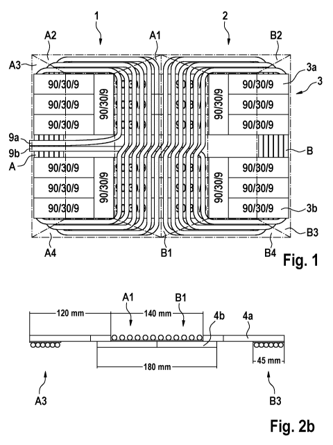
Figure 1 shows a top view of a coil apparatus according to
a preferred embodiment according to the present invention
with a first coil 1 and a second coil 2. The coils 1, 2
comprise a common electrical conductor and are thus
electrically connected in series. The coils 1, 2 are spiral-
Date Recue/Date Received 2021-08-04
CA 03128935 2021-08-04
- 9 -
shaped, arranged next to each other and can be electrically
contacted or connected via the two current supply conductors
or power connections 9a, 9b. Except for a few minor details,
the two coils 1, 2 are arranged and shaped so as to be
axially symmetrical in relation to each other. Each coil 1
and 2 comprises its own winding path A and B, respectively,
which respectively forms part of the common electrical
conductor and which is respectively divided into four path
sections or conductor sections. The first coil 1 is divided
into areas comprising a first path section Al, a second path
section A2, a third path section A3 and a fourth path section
A4, said path sections Al to A4 being arranged in a sequence
running counterclockwise. The second coil 2 is divided into
areas consisting of a first path section Bl, a second path
section B2, a third path section B3 and a fourth path section
B4, said path sections B1 to B4 being arranged in a sequence
running clockwise. The following path sections thus lie
opposite one another within a coil: path sections A2 and A4
(also designated as laterally arranged conductors/conductor
sections of the first coil) and path sections Al and A3 (also
designated as internally and externally arranged
conductors/conductor sections of the first coil), path
sections B2 and B4 (also designated as laterally arranged
conductors/conductor sections of the second coil) and path
sections B1 and B3 (also designated as internally and
externally arranged conductors/conductor sections of the
second coil). Furthermore, the path sections Al and B1 of
the first and second coils 1, 2 are directly adjacent to
each other. In the present invention, a path section defines
an area of the coil in which the conductors/conductor
sections arranged therein comprise specific properties with
regard to their arrangement and shaping. Deviations from
this definition exist at the transition boundaries between
the different winding path sections at which the conductors
describe a bend or curve and lead into the next winding path
section.
Date Recue/Date Received 2021-08-04
CA 03128935 2021-08-04
- 10 -
All winding path sections Al to A4 and B1 to B4 are
characterized in that the conductors arranged therein are
arranged so as to be essentially straight and parallel to
one another. The winding path sections Al and B1 exhibit an
exception, as in these sections the conductors each have a
kind of step or curvature in the middle. The function of the
step is to start a new turn or circuit of the first or second
coils, to increase the diameter of the turn towards the
centre of the coil apparatus and thus to allow the straight
and parallel formation of the remaining portions of the
common conductor, in particular in the sections Al and Bl.
The distance between two adjacent conductors in the path
sections Al and B1 is always the same and in particular
greater than the distance between the conductors in the path
sections A3 and B3. The properties of a bipolar coil topology
are attenuated by the larger spacing of the conductors in
sections Al and Bl. What is special about the sections A3
and B3 is the arrangement of the conductors: while, e.g., a
conductor in the sections Bl, B2 and B4 runs along the outer
edge of the coil, the same conductor in the section B3 is
arranged at the inner edge of the coil or at the coil opening.
The reverse is true for the inner conductors in the sections
Bl, B2 and B4, which are arranged in the section B3 at the
outer edge of the coil or coil apparatus. In the path
sections A2, A4, B2 and B4, the conductors are arranged in
pairs on top of each other in order to reduce the width of
the coil apparatus. The coil apparatus further comprises a
ferrite arrangement 3 consisting of two identically
configured ferrite plate assemblies 3a and 3b. It is noted
here that more than two and/or differently shaped and/or
sized ferrite plate assemblies can be used in other
embodiments. The ferrite plate assemblies 3a and 3b
respectively extend through the two coils 1 and 2 and over
the entire length of the coil apparatus, i.e. completely
from the left edge of the first coil 1 to the right edge of
the second coil 2. Depending on the height of the ferrite
arrangement, it is of course also possible for more than two
Date Recue/Date Received 2021-08-04
CA 03128935 2021-08-04
- 11 -
conductors to be arranged on top of one another in order to
make the coil apparatus more compact. On the side of the
coil apparatus, the current supply conductors 9a and 9b can
be be seen running between the ferrite plate assemblies 3a
and 3b into the centre of the coil apparatus and finally
forming coils 1 and 2 via a spiralling, i.e. a plurality of
turns, counterclockwise in the one case and clockwise in the
other, respectively.
Figure 2A shows a top view of the two ferrite plate
assemblies 3a and 3b from Figure 1, which are respectively
made of a plurality of identically configured ferrite plates
4. Each ferrite plate 4 is 90 mm long, 30 mm wide and 9 mm
high. Each ferrite plate assembly 3a and 3b is respectively
380 mm long and 90 mm wide and are arranged parallel to each
other in such a manner so as to cover a width of 210 mm.
That means that the ferrite plate assemblies 3a and 3b are
spaced apart from each other by 30mm. The ferrite plates 4
are arranged so as to be without gaps, parallel to and flush
with one another.
Figure 2B shows a longitudinal cross-section of the ferrite
plate assemblies 3a and 3b described above in Figure 2A,
wherein the conductors of the coils 1 and 2 are also shown.
The conductors from the winding path sections Al, A3, B1 and
B3 are depicted here, i.e. the internally and externally
arranged conductor/conductor sections of the first coil and
of the second coil. The ferrite arrangement comprises ferrite
plates 4a in a first upper plane and ferrite plates 4b in a
second lower plane. While the conductors in the path sections
A3 and B3 are respectively arranged directly next to one
another, the conductors in the path sections Al and B1 are
spaced evenly apart from one another. The conductors from
the path sections Al and B1 are arranged on the first upper
plane and the conductors of the path sections A3 and B3 are
arranged on the second lower plane. The total length of the
ferrite plates 4b arranged on the lower plane is 180 mm,
Date Recue/Date Received 2021-08-04
CA 03128935 2021-08-04
- 12 -
based on the length of two ferrite plates. The two ferrite
plate arrangements of the ferrite plates 4a on the first
plane each have a length of 120 mm, while the distance
between the two arrangements on the first plane is 140 mm.
Figure 2C indicates different types of ferrite plates, which
essentially differ in height and weight. All ferrite plates
have a length of 90 mm and a width of 30 mm. The 28 ferrite
plates with a height of 9 mm used in the coil apparatus in
Figure 1 for both ferrite arrangements 3a and 3b have a total
weight of 3.3 kg. It is noted that it is also possible to
use differently shaped and/or sized ferrite plates for the
embodiments disclosed herein.
Figure 3 shows a longitudinal cross-sectional view of a coil
apparatus according to a further preferred embodiment, which
comprises additional features in comparison with the coil
apparatus of Figure 1 or 2B. The entire coil apparatus has
a height of 23 mm. A 3 mm thick GRP cover plate 8, which is
420 mm long and 300 mm wide, is arranged on top of the coil
apparatus. Underneath, FRP frame profiles 7, respectively 18
mm high and wide, are arranged on the left and on the right
at the edge of the coil apparatus. Arranged between the
latter are the coils and ferrite arrangements with the
ferrite plates 4a, 4b, which have already been described in
Figures 1 and 2B. On the underside of the coil apparatus is
a 2 mm thick aluminium plate 6, which is exactly as wide and
long as the GRP cover plate 8.
Depicted in the first plane of the coil apparatus, as
described above in Figure 2B, are the conductors from the
winding path sections Al and Bl. A fibreglass fabric 10,
which has a thickness of 1 to 2 mm, is arranged between these
conductors and the lower ferrite plates 4b. The conductors
of the winding path sections A3 and B3 are arranged in the
second plane and are separated from the ferrite plates 4a
and from the aluminium plate 6 by fibreglass fabric layers
Date Recue/Date Received 2021-08-04
CA 03128935 2021-08-04
- 13 -
10. Arranged between the conductors of the winding path
sections A3 and B3 and the ferrite plates 4b are plastic
layers 5 with a thickness of 9 mm, which act as spacers and
structural support elements. The plastic layers 5 are 55 mm
wide and 9 mm high. The width of the winding path sections
A3 and B3 is respectively 45 mm.
Figure 4 shows three different cross-sectional views along
the width of the coil apparatus of Figure 3. The upper
drawing in Figure 4 shows a cross-section through the middle
of the coil apparatus, through the boundary line between the
described winding path sections Al and Bl. In particular,
the supply conductor 9b on the lower plane and a conductor
from the winding path section Al or B1 are shown. The middle
drawing of figure 4 depicts a cross-section at about one
quarter of the length of the coil apparatus. The two supply
conductors 9a and 9b in the middle as well as the conductors
arranged in pairs on top of each other in the path sections
A2 and A4 are clearly visible. The plastic layers 5 are also
indicated below the ferrite plates 4a. In the bottom drawing
of Figure 4, a cross-sectional view at the outermost edge of
the coil apparatus is depicted, the cross-section running
through the path section A3 and the conductor A from the
path section A3 being illustrated. The supply conductors 9a
and 9b are arranged above the latter.
Date Recue/Date Received 2021-08-04
CA 03128935 2021-08-04
- 14 -
LIST OF REFERENCE SIGNS
1 First coil
2 Second coil
3 Ferrite arrangement
3a First ferrite plate assembly
3b Second ferrite plate assembly
4 Ferrite plate
4a Ferrite plate from the first or upper plane
4b Ferrite plate from the second or lower plane
Plastic layer
6 Aluminium plate
7 FRP (fibre-reinforced plastic) frame profile
8 GRP (glass-reinforced plastic) cover plate
9a Supply conductor
9b Supply conductor
Fibreglass fabric layer
Al 1st path section of the 1st coil or internally arranged
conductors/conductor sections
A2 2nd path section of the 1st coil or laterally arranged
conductors/conductor sections
A3 3rd path section of the 1st coil or externally arranged
conductors/conductor sections
A4 4th path section of the 1st coil or laterally arranged
conductors/conductor sections
B1 1st path section of the 2nd coil or internally arranged
conductors/conductor sections
B2 2nd path section of the 2nd coil or laterally arranged
conductors/conductor sections
B3 3rd path section of the 2nd coil or externally arranged
conductors/conductor sections
B4 4th path section of the 2nd coil or laterally arranged
conductors/conductor sections
A First winding path (of the first coil)
B Second winding path (of the second coil)
Date Recue/Date Received 2021-08-04