Note: Descriptions are shown in the official language in which they were submitted.
CA 03128974 2021-08-04
WO 2019/165478
PCT/US2019/019691
INTEGRATED ROTOR DEVICES FOR AUTONOMOUS ANALYTICAL
CENTRIFUGATION, INTEGRATED CELL DEVICES FOR AUTONOMOUS
ANALYTICAL CENTRIFUGATION,
AND METHODS OF ASSEMBLY AND OPERATION OF SAME
RELATED APPLICATION
[001] This application claims the benefit of U.S. Provisional Application
No.
62/635,514 filed on February 26, 2018, the content of which is incorporated
herein by
reference in its entirety.
BACKGROUND
[002] Analytical Ultracentrifuge (AUC) instruments are centrifuges known
for
generating sedimentation data that can be deconvoluted for the determination
of size
distribution profiles in protein and other biological samples, for the purpose
of evaluating the
extent of aggregates or other impurities in fluid samples. An early example is
disclosed in US
Patent No. 1648369 the content of which is incorporated herein by reference,
wherein the
fundamental components of an AUC instrument are described in detail. Later
examples
include US Patent Nos. 2340825, 3391597, 3487994, and 4226537, the content of
each being
incorporated herein by reference, which present improvements to AUC instrument
design and
the introduction of improved supporting devices, including the AUC cell, which
is assembled
and inserted into specialized rotors that allow data collection via modules
within the
centrifuge.
[003] A standard procedure for the operation of a conventional AUC
instrument and its
accessory hardware components is to first assemble the AUC cell, which is a
layered
collection of windows, sector-shaped sample chamber, and outer housing and
screw rings.
Specifically, a sector-shaped geometry is defined as the volume element of a
cylindrical
segment having the cross-sectional area of a circular sector (an area enclosed
by two radii of
a large circle, the bounding arc of the larger circle between the radii, and
an arc of a smaller
concentric circle of lesser radius). Once torqued so as to render the sample
chamber fluid-
tight, the fluid sample may be loaded into the chamber through small ports,
which are also
subsequently sealed. The AUC cell is placed into a rotor which is typically
solid titanium
with cylindrical cavities parallel to the axis of rotation and arranged
symmetrically about said
axis of rotation. The rotor is placed inside the AUC instrument and allowed to
equilibrate to
the desired temperature via thermostatting of the centrifuge chamber,
controlled by
1
CA 03128974 2021-08-04
WO 2019/165478
PCT/US2019/019691
refrigeration or heating elements which are located inside the centrifuge. The
centrifuge is
also programmed to accelerate the rotor to the desired centrifugal velocity
and maintain the
velocity for a fixed period.
SUMMARY
[004] Embodiments relate to centrifugation, and, more specifically, to
analytical
centrifugation or ultracentrifugation systems and methods for detecting in
fluid samples the
degree of sedimentation of soluble molecules, aggregates, or particles. In
some
embodiments, detection can be performed in real time and continuously. In some
embodiments, detection can be performed during the course of the sedimentation
process.
Some embodiments provide for an assembly of modules or sub-units for sample
containment,
illumination and detection. In some embodiments, supporting functions are
integrated and
confined within the geometry of a rotor. In some embodiments, supporting
functions of the
sample interrogation, data generation and data collection, as well as
modulation and control
of sample condition, are integrated into units, and, in some embodiments,
assembled into
structures, or cells that are affixed within the rotor. The resulting
configuration can be
rotated by an externally applied centrifugal force, such as that supplied by a
standard floor-
model centrifuge, ultracentrifuge, or table-top centrifuge, which are commonly
available. In
some embodiments, the resulting self-contained, integrated device can
generate, store, and
transmit data for completing an analytical centrifugation or
ultracentrifugation experiment.
[005] In an aspect, a rotor system, comprises: a rotor constructed and
arranged to rotate
about an axis of rotation; a source of electromagnetic radiation at a first
position of the rotor,
the source of electromagnetic radiation configured to emit electromagnetic
radiation at one or
more wavelengths; a sample region; and a detector at a second position of the
rotor, the
detector constructed and arranged to receive electromagnetic radiation that
traverses at least a
portion of the sample region.
[006] In an embodiment, the rotor comprises a central opening.
[007] In an embodiment, the central opening is aligned with the axis of
rotation.
[008] In an embodiment, the rotor is constructed and arranged to mate with
a spindle.
[009] In an embodiment, the spindle is aligned with the axis of rotation.
[010] In an embodiment, the spindle comprises a spindle of a centrifuge.
[011] In an embodiment, the rotor is oriented symmetrically about the axis
of rotation.
[012] In an embodiment, the rotor comprises one or more sub-units
configured to be
stacked in a vertical direction of extension along the axis of rotation.
2
CA 03128974 2021-08-04
WO 2019/165478
PCT/US2019/019691
[013] In an embodiment, neighboring ones of the one or more stacked sub-
units are
coupled to each other at a threaded interface.
[014] In an embodiment, one or more of the one or more stacked sub-units
are coupled
with a bolt-through configuration.
[015] In an embodiment, a gasket is positioned between one or more of the
one or more
stacked sub-units.
[016] In an embodiment, the gasket is constructed and arranged to form a
sealed region.
[017] In an embodiment, the sealed region is sealed from an ambient region
external to
the sealed region.
[018] In an embodiment, one or more of the one or more sub-units are
coupled to each
other with a tongue-in-groove structure.
[019] In an embodiment, one or more of the one or more stacked sub-units
comprise
high-strength materials.
[020] In an embodiment, the high-strength material comprises titanium.
[021] In an embodiment, the high-strength material comprises an alloy
material.
[022] In an embodiment, the high-strength material comprises a composite
material.
[023] In an embodiment, the high-strength material comprises a material
including a
carbon fiber material.
[024] In an embodiment, the sample region comprises a sector shape.
[025] In an embodiment, the sample region comprises a sample chamber.
[026] In an embodiment, the sample chamber comprises a removable liner.
[027] In an embodiment, the first position and the second position are at
the sample
chamber and wherein the sample chamber comprises the source of electromagnetic
radiation
and the detector.
[028] In an embodiment, the sample region comprises an open top and an open
bottom.
[029] In an embodiment, the sample region is coupled to one or more
neighboring sub-
units.
[030] In an embodiment, a portion of the electromagnetic radiation emitted
from the
source of electromagnetic radiation is incident on the detector.
[031] In an embodiment, the electromagnetic radiation is directed toward
the sample
region.
[032] In an embodiment, the detector is arranged to detect electromagnetic
radiation that
traverses a portion of the sample region.
3
CA 03128974 2021-08-04
WO 2019/165478
PCT/US2019/019691
[033] In an embodiment, the sample region, the source of electromagnetic
radiation, and
the detector are arranged along an axis that is parallel to the axis of
rotation.
[034] In an embodiment, the source of electromagnetic radiation is
positioned at a first
of the one or more stacked sub-units.
[035] In an embodiment, the sample region is positioned at a second of the
one or more
stacked sub-units.
[036] In an embodiment, the detector is positioned at a third of the one or
more stacked
sub-units.
[037] In an embodiment, the system further comprises an alignment mechanism
that
aligns the first, second and third of the one or more stacked sub-units so
that the source of
electromagnetic radiation, the sample region and the detector being aligned in
a vertical
direction along an axis of interrogation that is parallel to the axis of
rotation.
[038] In an embodiment, a portion of the electromagnetic radiation emitted
from the
source of electromagnetic radiation traverses a portion of the sample chamber.
[039] In an embodiment, one or more wavelengths of the electromagnetic
radiation is
incident at the sample region.
[040] In an embodiment, electromagnetic radiation propagates through the
sample
region to the detector.
[041] In an embodiment, electromagnetic radiation triggers a reaction of
material at the
sample region.
[042] In an embodiment, the detector collects electromagnetic radiation
emitted from
the sample region and the electromagnetic radiation emitted from the sample
region
comprises one or more wavelengths that are different than the one or more
wavelengths
emitted from the source of electromagnetic radiation.
[043] In an embodiment, the wavelengths of the electromagnetic radiation
emitted from
the sample region are greater than the one or more wavelengths emitted from
the source of
electromagnetic radiation.
[044] In an embodiment, the wavelengths of the electromagnetic radiation
emitted from
the sample region are less than the one or more wavelengths emitted from the
source of
electromagnetic radiation.
[045] In an embodiment, the electromagnetic radiation triggers a
photophysical
interaction.
4
CA 03128974 2021-08-04
WO 2019/165478
PCT/US2019/019691
[046] In an embodiment, the photophysical interaction comprises excitation
of
molecules present in the sample region to energy levels above a ground state
of the sample
molecules.
[047] In an embodiment, the excitation of the energy levels consists of at
least one of
excitation of electronic energy levels, excitation of vibrational energy
levels or excitation of
rotational energy levels.
[048] In an embodiment, the source of electromagnetic radiation is one of a
plurality of
sources of electromagnetic radiation that is optically coupled with the
detector.
[049] In an embodiment, the source of electromagnetic radiation is coupled
to a circuit
board.
[050] In an embodiment, the rotor comprises one or more sub-units
configured to be
stacked in a vertical direction of extension along the axis of rotation and
wherein a topmost
sub-unit of the one or more sub-units comprises a source of electromagnetic
radiation
coupled to a circuit board.
[051] In an embodiment, the rotor comprises one or more sub-units
configured to be
stacked in a vertical direction of extension along the axis of rotation and
wherein a topmost
sub-unit of the one or more sub-units comprises a plurality of sources of
electromagnetic
radiation, wherein the sample region comprises a plurality of sample regions
and wherein the
detector comprises a plurality of detectors, each source of electromagnetic
radiation being
optically coupled to a corresponding detector through an optical path that
includes a
corresponding sample region.
[052] In an embodiment, the source of electromagnetic radiation is a single
light
emitting diode (LED).
[053] In an embodiment, the source of electromagnetic radiation comprises
an array of
light emitting diodes (LEDs).
[054] In an embodiment, the source of electromagnetic radiation comprises a
laser
diode.
[055] In an embodiment, the source of electromagnetic radiation comprises
and array of
laser diodes.
[056] In an embodiment, the detector comprises an array detector.
[057] In an embodiment, the detector comprises a point detector.
[058] In an embodiment, the detector comprises a CCD array.
[059] In an embodiment, the detector comprises a photodiode.
CA 03128974 2021-08-04
WO 2019/165478
PCT/US2019/019691
[060] In an embodiment, the detector periodically samples incident
electromagnetic
radiation.
[061] In an embodiment, the system further comprises a storage that stores
information
collected by the detector.
[062] In an embodiment, the system further comprises a transmitter that
transmits the
stored information stored by the storage to a receiver.
[063] In an embodiment, the transmitter transmits the stored information as
the rotor is
rotating about the axis of rotation.
[064] In an embodiment, the system transmits the stored information when
the rotor is
stationary.
[065] In an embodiment, the system is configured to measure light
absorbance of the
sample region based on the stored information collected by the detector.
[066] In an embodiment, the system is configured to provide spectroscopic
information
of the sample region based on the stored information collected by the
detector.
[067] In an embodiment, the system is configured to provide hyperspectral
image data
of the sample region based on the stored information collected by the
detector.
[068] In an embodiment, the system is configured to provide Schlieren
images of the
sample region based on the stored information collected by the detector.
[069] In an embodiment, the system is configured to provide fluorescence
images of the
sample region based on the stored information collected by the detector.
[070] In an embodiment, the system is configured to provide quantitative
fluorescence
emission data of the sample region based on the stored information collected
by the detector.
[071] In an embodiment, the quantitative fluorescence emission data
comprises a spatial
arrangement of the sample region.
[072] In an embodiment, the system further comprises a Fabry-Perot
interferometer
optically coupled with the source of electromagnetic radiation and the
detector.
[073] In an embodiment, the system further comprises one or more optical
filters
positioned between the source of electromagnetic radiation and the detector.
[074] In an embodiment, the system further comprises one or more optical
lenses
positioned between the source of electromagnetic radiation and the detector.
[075] In an embodiment, the system further comprises one or more mirrors
positioned
between the source of electromagnetic radiation and the detector.
[076] In an embodiment, the system further comprises one or more optical
diffusers
positioned between the source of electromagnetic radiation and the detector.
6
CA 03128974 2021-08-04
WO 2019/165478
PCT/US2019/019691
[077] In an embodiment, the system further comprises one or more optical
collimators
positioned between the source of electromagnetic radiation and the detector.
[078] In an embodiment, one or more of the one or more optical collimators
comprises
at least one self-collimating photonic crystal.
[079] In an embodiment, one or more of the one or more optical collimators
comprises
at least one micro-Fresnel lens.
[080] In an embodiment, the system further comprises one or more optical
lenses
positioned between the source of electromagnetic radiation and the detector
wherein the one
or more optical lenses are positioned relative to the sample region and the
detector such that
the detector detects an image of a plane at the sample region.
[081] In an embodiment, the one or more lenses are positioned below the
sample region.
[082] In an embodiment, the system further comprises an elongated edge
constructed
and arranged to block a portion of the light incident on the detector.
[083] In an embodiment, the system further comprises an iris constructed
and arranged
to block a portion of the light incident on the detector.
[084] In an embodiment, the system further comprises a beamsplitter system
constructed
and arranged to direct electromagnetic radiation from the source of
electromagnetic radiation
to a plurality of locations.
[085] In an embodiment, the beamsplitter system comprises at least one
mirror.
[086] In an embodiment, the beamsplitter system comprises at least one
filter.
[087] In an embodiment, the beamsplitter system comprises at least one
lens.
[088] In an embodiment, the beamsplitter system is constructed and arranged
such that
electromagnetic radiation emitted from a first sub-unit of the rotor is
optically coupled to a
detector on a second sub-unit of the rotor different than the first sub-unit.
[089] In an embodiment, the rotor comprises one or more sub-units
configured to be
stacked in a vertical direction of extension along the axis of rotation and
wherein one or more
of the one or more stacked sub-units are electrically connected with one or
more connectors.
[090] In an embodiment, the one or more connectors are configured to
transfer
information.
[091] In an embodiment, the one or more connectors are configured to
transfer power.
[092] In an embodiment, one or more of the one or more stacked sub-units
are
electrically connected with USB ports.
[093] In an embodiment, one or more of the one or more stacked sub-units
are
electrically connected with micro-USB ports.
7
CA 03128974 2021-08-04
WO 2019/165478
PCT/US2019/019691
[094] In an embodiment, one or more of the one or more stacked sub-units
are
electrically connected with VGA ports.
[095] In an embodiment, one or more of the one or more stacked sub-units
are
electrically connected with D-type connectors.
[096] In an embodiment, the system further comprises a transmitter
configured to
transmit information from the detector.
[097]
[098] In an embodiment, the transmitter is configured to transmit the
information in an
encrypted format.
[099] In an embodiment, the transmitter is configured to transmit the
information to a
cloud-based storage system.
[100] In an embodiment, the transmitter is configured to transmit
information
wireles sly.
[101] In an embodiment, the transmitter comprises an antenna.
[102] In an embodiment, the transmitter is configured to transmit the
information
optically.
[103] In an embodiment, the transmitter comprises a cable connection.
[104] In an embodiment, the cable connection comprises an electrical
connection.
[105] In an embodiment, the cable connection comprises fiber optics.
[106] In an embodiment, the cable connection comprises connection to a
circuit board.
[107] In an embodiment, the cable connection comprises connection to an on-
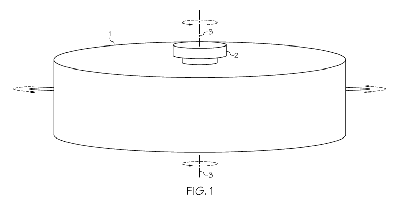
board
memory.
[108] In an embodiment, the on-board memory comprises a device selected
from the
group consisting of: a random access memory (RAM) device, a read-only memory
(ROM)
device, a solid-state memory (SSD) device, an SD memory card, or a micro-SD
memory
card.
[109] In an embodiment, the transmitter is positioned at a bottom portion
of the rotor.
[110] In an embodiment, the rotor comprises a central opening aligned with
the axis of
rotation.
[111] In an embodiment, the transmitter is constructed and arranged to
extend through
the central opening.
[112] In an embodiment, the transmitter extends from the bottom of the
rotor to the top
of the rotor.
8
CA 03128974 2021-08-04
WO 2019/165478
PCT/US2019/019691
[113] In an embodiment, the transmitter comprises one of a plurality of
transmitters.
[114] In an embodiment, the transmitter comprises a battery.
[115] In an embodiment, the system further comprises a recharging mechanism
that
recharges the battery, the recharging mechanism converting rotational energy
from the
rotation of the rotor into electrical current.
[116] In an embodiment, the recharging mechanism comprises an electric
generator
comprising a planetary gear configuration constructed and arranged to
facilitate relative
internal rotation in a rotor-stator pairing.
[117] In an embodiment, the system further comprises an on-board memory at
the rotor.
[118] In an embodiment, the on-board memory comprises a device selected
from the
group consisting of: a random access memory (RAM) device, a read-only memory
(ROM)
device, a solid-state memory (SSD) device, an SD memory card, or a micro-SD
memory
card.
[119] In an embodiment, the system further comprises a temperature control
system
configured to modify a temperature of the sample region.
[120] In an embodiment, the temperature control system is configured to
maintain the
temperature of the sample region.
[121] In an embodiment, maintaining the temperature comprises heating the
sample
region.
[122] In an embodiment, maintaining the temperature comprises cooling the
sample
region.
[123] In an embodiment, the temperature control system circulates thermally
conductive
material at the sample region.
[124] In an embodiment, the temperature control system comprises a pumping
system to
circulate the thermally conductive material.
[125] In an embodiment, the temperature control system heats the sample
region.
[126] In an embodiment, the temperature control system cools the sample
region.
[127] In an embodiment, the temperature control system circulates thermally
conductive
material through channels at one or more sub-units of the rotor.
[128] In an embodiment, the system further comprises a temperature sensor,
and
wherein the temperature control system adjusts the temperature of the sample
region in
response to an output of the temperature sensor.
[129] In an embodiment, the temperature sensor comprises a thermocouple.
[130] In an embodiment, the temperature sensor comprises an optical sensor.
9
CA 03128974 2021-08-04
WO 2019/165478
PCT/US2019/019691
[131] In an embodiment, the temperature sensor comprises an infrared
sensor.
[132] In an embodiment, the temperature sensor is one of a plurality of
temperature
sensors.
[133] In an embodiment, at least two of the plurality of temperature
sensors are in
communication with each other.
[134] In an embodiment, the temperature control system comprises an open-
loop
temperature system.
[135] In an embodiment, the temperature control system comprises a closed-
loop
temperature feedback system.
[136] In an embodiment, the system further comprises a sample chamber at
the sample
region and wherein the temperature control system is configured to adjust a
temperature of
the sample chamber.
[137] In an embodiment, the temperature control system is positioned at the
sample
region.
[138] In an embodiment, the temperature control system comprises a
thermoelectric or
Peltier device.
[139] In an embodiment, the rotor comprises one or more sub-units
configured to be
stacked in a vertical direction of extension along the axis of rotation and
wherein one or more
of the one or more stacked sub-units comprises a power source.
[140] In an embodiment, the power source comprises at least one battery.
[141] In an embodiment, the at least one battery is positioned on a first
sub-unit and
supplies power to a device on a second sub-unit.
[142] In an embodiment, each of the one or more sub-units comprises a power
source.
[143] In an embodiment, the power source comprises a recharging mechanism
constructed and arranged to convert the rotational energy of the rotor into
electrical current.
[144] In an embodiment, the recharging mechanism comprises at least one
voltaic cell.
[145] In an embodiment, the at least one voltaic cell comprises two
electrodes separated
by an electrolyte solution.
[146] In an embodiment, the current is driven by an electrolyte
concentration difference
in the electrolyte solution that is induced by centrifugation.
[147] In an embodiment, the at least one voltaic cell comprises a
concentration cell.
[148] In an embodiment, the at least one voltaic cell is driven by a radio-
isotopic decay.
[149] In an embodiment, the at least one voltaic cell comprises a beta-
voltaic cell.
CA 03128974 2021-08-04
WO 2019/165478
PCT/US2019/019691
[150] In an embodiment, the system further comprises a recharging mechanism
that
recharges the battery, the recharging mechanism converting rotational energy
from the
rotation of the rotor into electrical current.
[151] In an embodiment, the recharging mechanism comprises an electric
generator
comprising a planetary gear configuration constructed and arranged to
facilitate relative
internal rotation in a rotor-stator pairing.
[152] In another aspect, an integrated rotor system, comprises: a rotor
comprising at
least one rotor cavity, the rotor being constructed and arranged to rotate
about an axis of
rotation; and an interrogation cell positioned in the at least one rotor
cavity. The
interrogation cell comprises: a source of electromagnetic radiation at a first
position of the
interrogation cell, the source of electromagnetic radiation configured to emit
electromagnetic
radiation at one or more wavelengths; a sample region; and a detector at a
second position of
the interrogation cell, the detector configured to receive electromagnetic
radiation that
traverses at least a portion of the sample region.
[153] In an embodiment, the at least one rotor cavity comprises a plurality
of rotor
cavities.
[154] In an embodiment, the system further comprises a plurality of
interrogation cells,
each interrogation cell corresponding to one of the plurality of rotor
cavities.
[155] In an embodiment, the rotor comprises a central opening.
[156] In an embodiment, the central opening is aligned with the axis of
rotation.
[157] In an embodiment, the rotor is constructed and arranged to mate with
a spindle.
[158] In an embodiment, the spindle is aligned with the axis of rotation.
[159] In an embodiment, the spindle comprises a spindle of a centrifuge.
[160] In an embodiment, the rotor is oriented symmetrically about the axis
of rotation.
[161] In an embodiment, the interrogation cell comprises one or more sub-
units
configured to be stacked in a vertical direction of extension along the axis
of rotation.
[162] In an embodiment, neighboring ones of the one or more stacked sub-
units are
coupled to each other at a threaded interface.
[163] In an embodiment, one or more of the one or more stacked sub-units
are coupled
with a bolt-through configuration.
[164] In an embodiment, a gasket is positioned between one or more of the
one or more
stacked sub-units.
[165] In an embodiment, the gasket is constructed and arranged to form a
sealed region.
11
CA 03128974 2021-08-04
WO 2019/165478
PCT/US2019/019691
[166] In an embodiment, the sealed region is sealed from an ambient region
external to
the sealed region.
[167] In an embodiment, one or more of the one or more sub-units are
coupled to each
other with a tongue-in-groove structure.
[168] In an embodiment, one or more of the one or more stacked sub-units
comprise
high-strength materials.
[169] In an embodiment, the high-strength material comprises titanium.
[170] In an embodiment, the high-strength material comprises an alloy
material.
[171] In an embodiment, the high-strength material comprises a composite
material.
[172] In an embodiment, the high-strength material comprises a material
including a
carbon fiber material.
[173] In an embodiment, the sample region comprises a sector shape.
[174] In an embodiment, the sample region comprises a sample chamber.
[175] In an embodiment, the sample chamber comprises a removable liner.
[176] In an embodiment, the first position and the second position are at
the sample
chamber and wherein the sample chamber comprises the source of electromagnetic
radiation
and the detector.
[177] In an embodiment, the sample region comprises an open top and an open
bottom.
[178] In an embodiment, the sample region is coupled to one or more
neighboring sub-
units.
[179] In an embodiment, a portion of the electromagnetic radiation emitted
from the
source of electromagnetic radiation is incident on the detector.
[180] In an embodiment, the electromagnetic radiation is directed toward
the sample
region.
[181] In an embodiment, the detector is arranged to detect electromagnetic
radiation that
traverses a portion of the sample region.
[182] In an embodiment, the sample region, the source of electromagnetic
radiation, and
the detector are arranged along an axis that is parallel to the axis of
rotation.
[183] In an embodiment, the source of electromagnetic radiation is
positioned at a first
of the one or more stacked sub-units.
[184] In an embodiment, the sample region is positioned at a second of the
one or more
stacked sub-units.
[185] In an embodiment, the detector is positioned at a third of the one or
more stacked
sub-units.
12
CA 03128974 2021-08-04
WO 2019/165478
PCT/US2019/019691
[186] In an embodiment, the system further comprises an alignment mechanism
that
aligns the first, second and third of the one or more stacked sub-units so
that the source of
electromagnetic radiation, the sample region and the detector being aligned in
a vertical
direction along an axis of interrogation that is parallel to the axis of
rotation.
[187] In an embodiment, a portion of the electromagnetic radiation emitted
from the
source of electromagnetic radiation traverses a portion of the sample chamber.
[188] In an embodiment, one or more wavelengths of the electromagnetic
radiation is
incident at the sample region.
[189] In an embodiment, electromagnetic radiation propagates through the
sample
region to the detector.
[190] In an embodiment, electromagnetic radiation triggers a reaction of
material at the
sample region.
[191] In an embodiment, the detector collects electromagnetic radiation
emitted from
the sample region and the electromagnetic radiation emitted from the sample
region
comprises one or more wavelengths that are different than the one or more
wavelengths
emitted from the source of electromagnetic radiation.
[192] In an embodiment, the wavelengths of the electromagnetic radiation
emitted from
the sample region are greater than the one or more wavelengths emitted from
the source of
electromagnetic radiation.
[193] In an embodiment, the wavelengths of the electromagnetic radiation
emitted from
the sample region are less than the one or more wavelengths emitted from the
source of
electromagnetic radiation.
[194] In an embodiment, the electromagnetic radiation triggers a
photophysical
interaction.
[195] In an embodiment, the photophysical interaction comprises excitation
of
molecules present in the sample region to energy levels above a ground state
of the sample
molecules.
[196] In an embodiment, the excitation of the energy levels consists of at
least one of
excitation of electronic energy levels, excitation of vibrational energy
levels or excitation of
rotational energy levels.
[197] In an embodiment, the source of electromagnetic radiation is one of a
plurality of
sources of electromagnetic radiation that is optically coupled with the
detector.
[198] In an embodiment, the source of electromagnetic radiation is coupled
to a circuit
board.
13
CA 03128974 2021-08-04
WO 2019/165478
PCT/US2019/019691
[199] In an embodiment, the interrogation cell comprises one or more sub-
units
configured to be stacked in a vertical direction of extension along the axis
of rotation and
wherein a topmost sub-unit of the one or more sub-units comprises a source of
electromagnetic radiation coupled to a circuit board.
[200] In an embodiment, the interrogation cell comprises one or more sub-
units
configured to be stacked in a vertical direction of extension along the axis
of rotation and
wherein a topmost sub-unit of the one or more sub-units comprises a plurality
of sources of
electromagnetic radiation, wherein the sample region comprises a plurality of
sample regions
and wherein the detector comprises a plurality of detectors, each source of
electromagnetic
radiation being optically coupled to a corresponding detector through an
optical path that
includes a corresponding sample region.
[201] In an embodiment, the source of electromagnetic radiation is a single
light
emitting diode (LED).
[202] In an embodiment, the source of electromagnetic radiation comprises
an array of
light emitting diodes (LEDs).
[203] In an embodiment, the source of electromagnetic radiation comprises a
laser
diode.
[204] In an embodiment, the source of electromagnetic radiation comprises
and array of
laser diodes.
[205] In an embodiment, the detector comprises an array detector.
[206] In an embodiment, the detector comprises a point detector.
[207] In an embodiment, the detector comprises a CCD array.
[208] In an embodiment, the detector comprises a photodiode.
[209] In an embodiment, the detector periodically samples incident
electromagnetic
radiation.
[210] In an embodiment, the system further comprises a storage that stores
information
collected by the detector.
[211] In an embodiment, the system further comprises a transmitter that
transmits the
stored information stored by the storage to a receiver.
[212] In an embodiment, the transmitter transmits the stored information as
the rotor is
rotating about the axis of rotation.
[213] In an embodiment, the system transmits the stored information when
the rotor is
stationary.
14
CA 03128974 2021-08-04
WO 2019/165478
PCT/US2019/019691
[214] In an embodiment, the system is configured to measure light
absorbance of the
sample region based on the stored information collected by the detector.
[215] In an embodiment, the system is configured to provide spectroscopic
information
of the sample region based on the stored information collected by the
detector.
[216] In an embodiment, the system is configured to provide hyperspectral
image data
of the sample region based on the stored information collected by the
detector.
[217] In an embodiment, the system is configured to provide Schlieren
images of the
sample region based on the stored information collected by the detector.
[218] In an embodiment, the system is configured to provide fluorescence
images of the
sample region based on the stored information collected by the detector.
[219] In an embodiment, the system is configured to provide quantitative
fluorescence
emission data of the sample region based on the stored information collected
by the detector.
[220] In an embodiment, the quantitative fluorescence emission data
comprises a spatial
arrangement of the sample region.
[221] In an embodiment, the system further comprises a Fabry-Perot
interferometer
optically coupled with the source of electromagnetic radiation and the
detector.
[222] In an embodiment, the system further comprises one or more optical
filters
positioned between the source of electromagnetic radiation and the detector.
[223] In an embodiment, the system further comprises one or more optical
lenses
positioned between the source of electromagnetic radiation and the detector.
[224] In an embodiment, the system further comprises one or more mirrors
positioned
between the source of electromagnetic radiation and the detector.
[225] In an embodiment, the system further comprises one or more optical
diffusers
positioned between the source of electromagnetic radiation and the detector.
[226] In an embodiment, the system further comprises one or more optical
collimators
positioned between the source of electromagnetic radiation and the detector.
[227] In an embodiment, one or more of the one or more optical collimators
comprises
at least one self-collimating photonic crystal.
[228] In an embodiment, one or more of the one or more optical collimators
comprises
at least one micro-Fresnel lens.
[229] In an embodiment, the system further comprises one or more optical
lenses
positioned between the source of electromagnetic radiation and the detector
wherein the one
or more optical lenses are positioned relative to the sample region and the
detector such that
the detector detects an image of a plane at the sample region.
CA 03128974 2021-08-04
WO 2019/165478
PCT/US2019/019691
[230] In an embodiment, the one or more lenses are positioned below the
sample region.
[231] In an embodiment, the system further comprises an elongated edge
constructed
and arranged to block a portion of the light incident on the detector.
[232] In an embodiment, the system further comprises an iris constructed
and arranged
to block a portion of the light incident on the detector.
[233] In an embodiment, the system further comprises a beamsplitter system
constructed
and arranged to direct electromagnetic radiation from the source of
electromagnetic radiation
to a plurality of locations.
[234] In an embodiment, the beamsplitter system comprises at least one
mirror.
[235] In an embodiment, the beamsplitter system comprises at least one
filter.
[236] In an embodiment, the beamsplitter system comprises at least one
lens.
[237] In an embodiment, the beamsplitter system is constructed and arranged
such that
electromagnetic radiation emitted from a first sub-unit of the interrogation
cell is optically
coupled to a detector on a second sub-unit of the interrogation cell different
than the first sub-
unit.
[238] In an embodiment, the interrogation cell comprises one or more sub-
units
configured to be stacked in a vertical direction of extension along the axis
of rotation and
wherein one or more of the one or more stacked sub-units are electrically
connected with one
or more connectors.
[239] In an embodiment, the one or more connectors are configured to
transfer
information.
[240] In an embodiment, the one or more connectors are configured to
transfer power.
[241] In an embodiment, one or more of the one or more stacked sub-units
are
electrically connected with USB ports.
[242] In an embodiment, one or more of the one or more stacked sub-units
are
electrically connected with micro-USB ports.
[243] In an embodiment, one or more of the one or more stacked sub-units
are
electrically connected with VGA ports.
[244] In an embodiment, one or more of the one or more stacked sub-units
are
electrically connected with D-type connectors.
[245] In an embodiment, the system further comprises a transmitter
configured to
transmit information from the detector.
[246]
16
CA 03128974 2021-08-04
WO 2019/165478
PCT/US2019/019691
[247] In an embodiment, the transmitter is configured to transmit the
information in an
encrypted format.
[248] In an embodiment, the transmitter is configured to transmit the
information to a
cloud-based storage system.
[249] In an embodiment, the transmitter is configured to transmit
information
wireles sly.
[250] In an embodiment, the transmitter comprises an antenna.
[251] In an embodiment, the transmitter is configured to transmit the
information
optically.
[252] In an embodiment, the transmitter comprises a cable connection.
[253] In an embodiment, the cable connection comprises an electrical
connection.
[254] In an embodiment, the cable connection comprises fiber optics.
[255] In an embodiment, the cable connection comprises connection to a
circuit board.
[256] In an embodiment, the cable connection comprises connection to an on-
board
memory.
[257] In an embodiment, the on-board memory comprises a device selected
from the
group consisting of: a random access memory (RAM) device, a read-only memory
(ROM)
device, a solid-state memory (SSD) device, an SD memory card, or a micro-SD
memory
card.
[258] In an embodiment, the transmitter is positioned at a bottom portion
of the
interrogation cell.
[259] In an embodiment, the rotor comprises a central opening aligned with
the axis of
rotation.
[260] In an embodiment, the transmitter is constructed and arranged to
extend through
the central opening.
[261] In an embodiment, the transmitter extends from the bottom of the
rotor to the top
of the rotor.
[262] In an embodiment, the transmitter comprises one of a plurality of
transmitters.
[263] In an embodiment, the transmitter comprises a battery.
[264] In an embodiment, the system further comprises a recharging mechanism
that
recharges the battery, the recharging mechanism converting rotational energy
from the
rotation of the rotor into electrical current.
17
CA 03128974 2021-08-04
WO 2019/165478
PCT/US2019/019691
[265] In an embodiment, the recharging mechanism comprises an electric
generator
comprising a planetary gear configuration constructed and arranged to
facilitate relative
internal rotation in a rotor-stator pairing.
[266] In an embodiment, the system further comprises an on-board memory at
the
interrogation cell.
[267] In an embodiment, the on-board memory comprises a device selected
from the
group consisting of: a random access memory (RAM) device, a read-only memory
(ROM)
device, a solid-state memory (SSD) device, an SD memory card, or a micro-SD
memory
card.
[268] In an embodiment, the system further comprises a temperature control
system
configured to modify a temperature of the sample region.
[269] In an embodiment, the temperature control system is configured to
maintain the
temperature of the sample region.
[270] In an embodiment, maintaining the temperature comprises heating the
sample
region.
[271] In an embodiment, maintaining the temperature comprises cooling the
sample
region.
[272] In an embodiment, the temperature control system circulates thermally
conductive
material at the sample region.
[273] In an embodiment, the temperature control system comprises a pumping
system to
circulate the thermally conductive material.
[274] In an embodiment, the temperature control system heats the sample
region.
[275] In an embodiment, the temperature control system cools the sample
region.
[276] In an embodiment, the temperature control system circulates thermally
conductive
material through channels at one or more sub-units of the interrogation cell.
[277] In an embodiment, the system further comprises a temperature sensor,
and
wherein the temperature control system adjusts the temperature of the sample
region in
response to an output of the temperature sensor.
[278] In an embodiment, the temperature sensor comprises a thermocouple.
[279] In an embodiment, the temperature sensor comprises an optical sensor.
[280] In an embodiment, the temperature sensor comprises an infrared
sensor.
[281] In an embodiment, the temperature sensor is one of a plurality of
temperature
sensors.
18
CA 03128974 2021-08-04
WO 2019/165478
PCT/US2019/019691
[282] In an embodiment, at least two of the plurality of temperature
sensors are in
communication with each other.
[283] In an embodiment, the temperature control system comprises an open-
loop
temperature system.
[284] In an embodiment, the temperature control system comprises a closed-
loop
temperature feedback system.
[285] In an embodiment, the system further comprises a sample chamber at
the sample
region and wherein the temperature control system is configured to adjust a
temperature of
the sample chamber.
[286] In an embodiment, the temperature control system is positioned at the
sample
region.
[287] In an embodiment, the temperature control system comprises a
thermoelectric or
Peltier device.
[288] In an embodiment, the interrogation cell comprises one or more sub-
units
configured to be stacked in a vertical direction of extension along the axis
of rotation and
wherein one or more of the one or more stacked sub-units comprises a power
source.
[289] In an embodiment, the power source comprises at least one battery.
[290] In an embodiment, the at least one battery is positioned on a first
sub-unit and
supplies power to a device on a second sub-unit.
[291] In an embodiment, each of the one or more sub-units comprises a power
source.
[292] In an embodiment, the power source comprises a recharging mechanism
constructed and arranged to convert the rotational energy of the rotor into
electrical current.
[293] In an embodiment, the recharging mechanism comprises at least one
voltaic cell.
[294] In an embodiment, the at least one voltaic cell comprises two
electrodes separated
by an electrolyte solution.
[295] In an embodiment, the current is driven by an electrolyte
concentration difference
in the electrolyte solution that is induced by centrifugation.
[296] In an embodiment, the at least one voltaic cell comprises a
concentration cell.
[297] In an embodiment, the at least one voltaic cell is driven by a radio-
isotopic decay.
[298] In an embodiment, the at least one voltaic cell comprises a beta-
voltaic cell.
[299] In an embodiment, the system further comprises a recharging mechanism
that
recharges the battery, the recharging mechanism converting rotational energy
from the
rotation of the rotor into electrical current.
19
CA 03128974 2021-08-04
WO 2019/165478
PCT/US2019/019691
[300] In an embodiment, the recharging mechanism comprises an electric
generator
comprising a planetary gear configuration constructed and arranged to
facilitate relative
internal rotation in a rotor-stator pairing.
[301] In another aspect, an interrogation cell, comprises; a source of
electromagnetic
radiation at a first position, the source of electromagnetic radiation
configured to emit
electromagnetic radiation at one or more wavelengths; a sample region; and a
detector at a
second position, the detector configured to receive electromagnetic radiation
that traverses at
least a portion of the sample region, wherein the interrogation cell is
dimensioned for
positioning in a rotor cavity of a centrifuge rotor.
[302] In an embodiment, the interrogation cell comprises one or more sub-
units
configured to be stacked in a vertical direction of extension along the axis
of rotation.
[303] In an embodiment, neighboring ones of the one or more stacked sub-
units are
coupled to each other at a threaded interface.
[304] In an embodiment, one or more of the one or more stacked sub-units
are coupled
with a bolt-through configuration.
[305] In an embodiment, a gasket is positioned between one or more of the
one or more
stacked sub-units.
[306] In an embodiment, the gasket is constructed and arranged to form a
sealed region.
[307] In an embodiment, the sealed region is sealed from an ambient region
external to
the sealed region.
[308] In an embodiment, one or more of the one or more sub-units are
coupled to each
other with a tongue-in-groove structure.
[309] In an embodiment, one or more of the one or more stacked sub-units
comprise
high-strength materials.
[310] In an embodiment, the high-strength material comprises titanium.
[311] In an embodiment, the high-strength material comprises an alloy
material.
[312] In an embodiment, the high-strength material comprises a composite
material.
[313] In an embodiment, the high-strength material comprises a material
including a
carbon fiber material.
[314] In an embodiment, the sample region comprises a sector shape.
[315] In an embodiment, the sample region comprises a sample chamber.
[316] In an embodiment, the sample chamber comprises a removable liner.
CA 03128974 2021-08-04
WO 2019/165478
PCT/US2019/019691
[317] In an embodiment, the first position and the second position are at
the sample
chamber and wherein the sample chamber comprises the source of electromagnetic
radiation
and the detector.
[318] In an embodiment, the sample region comprises an open top and an open
bottom.
[319] In an embodiment, the sample region is coupled to one or more
neighboring sub-
units.
[320] In an embodiment, a portion of the electromagnetic radiation emitted
from the
source of electromagnetic radiation is incident on the detector.
[321] In an embodiment, the electromagnetic radiation is directed toward
the sample
region.
[322] In an embodiment, the detector is arranged to detect electromagnetic
radiation that
traverses a portion of the sample region.
[323] In an embodiment, the sample region, the source of electromagnetic
radiation, and
the detector are arranged along an axis that is parallel to the axis of
rotation.
[324] In an embodiment, the source of electromagnetic radiation is
positioned at a first
of the one or more stacked sub-units.
[325] In an embodiment, the sample region is positioned at a second of the
one or more
stacked sub-units.
[326] In an embodiment, the detector is positioned at a third of the one or
more stacked
sub-units.
[327] In an embodiment, the system further comprises an alignment mechanism
that
aligns the first, second and third of the one or more stacked sub-units so
that the source of
electromagnetic radiation, the sample region and the detector being aligned in
a vertical
direction along an axis of interrogation that is parallel to the axis of
rotation.
[328] In an embodiment, a portion of the electromagnetic radiation emitted
from the
source of electromagnetic radiation traverses a portion of the sample chamber.
[329] In an embodiment, one or more wavelengths of the electromagnetic
radiation is
incident at the sample region.
[330] In an embodiment, electromagnetic radiation propagates through the
sample
region to the detector.
[331] In an embodiment, electromagnetic radiation triggers a reaction of
material at the
sample region.
[332] In an embodiment, the detector collects electromagnetic radiation
emitted from
the sample region and the electromagnetic radiation emitted from the sample
region
21
CA 03128974 2021-08-04
WO 2019/165478
PCT/US2019/019691
comprises one or more wavelengths that are different than the one or more
wavelengths
emitted from the source of electromagnetic radiation.
[333] In an embodiment, the wavelengths of the electromagnetic radiation
emitted from
the sample region are greater than the one or more wavelengths emitted from
the source of
electromagnetic radiation.
[334] In an embodiment, the wavelengths of the electromagnetic radiation
emitted from
the sample region are less than the one or more wavelengths emitted from the
source of
electromagnetic radiation.
[335] In an embodiment, the electromagnetic radiation triggers a
photophysical
interaction.
[336] In an embodiment, the photophysical interaction comprises excitation
of
molecules present in the sample region to energy levels above a ground state
of the sample
molecules.
[337] In an embodiment, the excitation of the energy levels consists of at
least one of
excitation of electronic energy levels, excitation of vibrational energy
levels or excitation of
rotational energy levels.
[338] In an embodiment, the source of electromagnetic radiation is one of a
plurality of
sources of electromagnetic radiation that is optically coupled with the
detector.
[339] In an embodiment, the source of electromagnetic radiation is coupled
to a circuit
board.
[340] In an embodiment, the interrogation cell comprises one or more sub-
units
configured to be stacked in a vertical direction of extension along the axis
of rotation and
wherein a topmost sub-unit of the one or more sub-units comprises a source of
electromagnetic radiation coupled to a circuit board.
[341] In an embodiment, the interrogation cell comprises one or more sub-
units
configured to be stacked in a vertical direction of extension along the axis
of rotation and
wherein a topmost sub-unit of the one or more sub-units comprises a plurality
of sources of
electromagnetic radiation, wherein the sample region comprises a plurality of
sample regions
and wherein the detector comprises a plurality of detectors, each source of
electromagnetic
radiation being optically coupled to a corresponding detector through an
optical path that
includes a corresponding sample region.
[342] In an embodiment, the source of electromagnetic radiation is a single
light
emitting diode (LED).
22
CA 03128974 2021-08-04
WO 2019/165478
PCT/US2019/019691
[343] In an embodiment, the source of electromagnetic radiation comprises
an array of
light emitting diodes (LEDs).
[344] In an embodiment, the source of electromagnetic radiation comprises a
laser
diode.
[345] In an embodiment, the source of electromagnetic radiation comprises
and array of
laser diodes.
[346] In an embodiment, the detector comprises an array detector.
[347] In an embodiment, the detector comprises a point detector.
[348] In an embodiment, the detector comprises a CCD array.
[349] In an embodiment, the detector comprises a photodiode.
[350] In an embodiment, the detector periodically samples incident
electromagnetic
radiation.
[351] In an embodiment, the system further comprises a storage that stores
information
collected by the detector.
[352] In an embodiment, the system further comprises a transmitter that
transmits the
stored information stored by the storage to a receiver.
[353] In an embodiment, the transmitter transmits the stored information as
the
interrogation cell is rotating about the axis of rotation of the rotor.
[354] In an embodiment, the system transmits the stored information when
the
interrogation cell is stationary.
[355] In an embodiment, the system is configured to measure light
absorbance of the
sample region based on the stored information collected by the detector.
[356] In an embodiment, the system is configured to provide spectroscopic
information
of the sample region based on the stored information collected by the
detector.
[357] In an embodiment, the system is configured to provide hyperspectral
image data
of the sample region based on the stored information collected by the
detector.
[358] In an embodiment, the system is configured to provide Schlieren
images of the
sample region based on the stored information collected by the detector.
[359] In an embodiment, the system is configured to provide fluorescence
images of the
sample region based on the stored information collected by the detector.
[360] In an embodiment, the system is configured to provide quantitative
fluorescence
emission data of the sample region based on the stored information collected
by the detector.
[361] In an embodiment, the quantitative fluorescence emission data
comprises a spatial
arrangement of the sample region.
23
CA 03128974 2021-08-04
WO 2019/165478
PCT/US2019/019691
[362] In an embodiment, the system further comprises a Fabry-Perot
interferometer
optically coupled with the source of electromagnetic radiation and the
detector.
[363] In an embodiment, the system further comprises one or more optical
filters
positioned between the source of electromagnetic radiation and the detector.
[364] In an embodiment, the system further comprises one or more optical
lenses
positioned between the source of electromagnetic radiation and the detector.
[365] In an embodiment, the system further comprises one or more mirrors
positioned
between the source of electromagnetic radiation and the detector.
[366] In an embodiment, the system further comprises one or more optical
diffusers
positioned between the source of electromagnetic radiation and the detector.
[367] In an embodiment, the system further comprises one or more optical
collimators
positioned between the source of electromagnetic radiation and the detector.
[368] In an embodiment, one or more of the one or more optical collimators
comprises
at least one self-collimating photonic crystal.
[369] In an embodiment, one or more of the one or more optical collimators
comprises
at least one micro-Fresnel lens.
[370] In an embodiment, the system further comprises one or more optical
lenses
positioned between the source of electromagnetic radiation and the detector
wherein the one
or more optical lenses are positioned relative to the sample region and the
detector such that
the detector detects an image of a plane at the sample region.
[371] In an embodiment, the one or more lenses are positioned below the
sample region.
[372] In an embodiment, the system further comprises an elongated edge
constructed
and arranged to block a portion of the light incident on the detector.
[373] In an embodiment, the system further comprises an iris constructed
and arranged
to block a portion of the light incident on the detector.
[374] In an embodiment, the system further comprises a beamsplitter system
constructed
and arranged to direct electromagnetic radiation from the source of
electromagnetic radiation
to a plurality of locations.
[375] In an embodiment, the beamsplitter system comprises at least one
mirror.
[376] In an embodiment, the beamsplitter system comprises at least one
filter.
[377] In an embodiment, the beamsplitter system comprises at least one
lens.
[378] In an embodiment, the beamsplitter system is constructed and arranged
such that
electromagnetic radiation emitted from a first sub-unit of the interrogation
cell is optically
24
CA 03128974 2021-08-04
WO 2019/165478
PCT/US2019/019691
coupled to a detector on a second sub-unit of the interrogation cell different
than the first sub-
unit.
[379] In an embodiment, the interrogation cell comprises one or more sub-
units
configured to be stacked in a vertical direction of extension along the axis
of rotation and
wherein one or more of the one or more stacked sub-units are electrically
connected with one
or more connectors.
[380] In an embodiment, the one or more connectors are configured to
transfer
information.
[381] In an embodiment, the one or more connectors are configured to
transfer power.
[382] In an embodiment, one or more of the one or more stacked sub-units
are
electrically connected with USB ports.
[383] In an embodiment, one or more of the one or more stacked sub-units
are
electrically connected with micro-USB ports.
[384] In an embodiment, one or more of the one or more stacked sub-units
are
electrically connected with VGA ports.
[385] In an embodiment, one or more of the one or more stacked sub-units
are
electrically connected with D-type connectors.
[386] In an embodiment, the system further comprises a transmitter
configured to
transmit information from the detector.
[387] In an embodiment, the transmitter is configured to transmit the
information in an
encrypted format.
[388] In an embodiment, the transmitter is configured to transmit the
information to a
cloud-based storage system.
[389] In an embodiment, the transmitter is configured to transmit
information
wireles sly.
[390] In an embodiment, the transmitter comprises an antenna.
[391] In an embodiment, the transmitter is configured to transmit the
information
optically.
[392] In an embodiment, the transmitter comprises a cable connection.
[393] In an embodiment, the cable connection comprises an electrical
connection.
[394] In an embodiment, the cable connection comprises fiber optics.
[395] In an embodiment, the cable connection comprises connection to a
circuit board.
[396] In an embodiment, the cable connection comprises connection to an on-
board
memory.
CA 03128974 2021-08-04
WO 2019/165478
PCT/US2019/019691
[397] In an embodiment, the on-board memory comprises a device selected
from the
group consisting of: a random access memory (RAM) device, a read-only memory
(ROM)
device, a solid-state memory (SSD) device, an SD memory card, or a micro-SD
memory
card.
[398] In an embodiment, the transmitter is positioned at a bottom portion
of the
interrogation cell.
[399] In an embodiment, the transmitter comprises one of a plurality of
transmitters.
[400] In an embodiment, the transmitter comprises a battery.
[401] In an embodiment, the system further comprises an on-board memory at
the
interrogation cell.
[402] In an embodiment, the on-board memory comprises a device selected
from the
group consisting of: a random access memory (RAM) device, a read-only memory
(ROM)
device, a solid-state memory (SSD) device, an SD memory card, or a micro-SD
memory
card.
[403] In an embodiment, the system further comprises a temperature control
system
configured to modify a temperature of the sample region.
[404] In an embodiment, the temperature control system is configured to
maintain the
temperature of the sample region.
[405] In an embodiment, maintaining the temperature comprises heating the
sample
region.
[406] In an embodiment, maintaining the temperature comprises cooling the
sample
region.
[407] In an embodiment, the temperature control system circulates thermally
conductive
material at the sample region.
[408] In an embodiment, the temperature control system comprises a pumping
system to
circulate the thermally conductive material.
[409] In an embodiment, the temperature control system heats the sample
region.
[410] In an embodiment, the temperature control system cools the sample
region.
[411] In an embodiment, the temperature control system circulates thermally
conductive
material through channels at one or more sub-units of the interrogation cell.
[412] In an embodiment, the system further comprises a temperature sensor,
and
wherein the temperature control system adjusts the temperature of the sample
region in
response to an output of the temperature sensor.
[413] In an embodiment, the temperature sensor comprises a thermocouple.
26
CA 03128974 2021-08-04
WO 2019/165478
PCT/US2019/019691
[414] In an embodiment, the temperature sensor comprises an optical sensor.
[415] In an embodiment, the temperature sensor comprises an infrared
sensor.
[416] In an embodiment, the temperature sensor is one of a plurality of
temperature
sensors.
[417] In an embodiment, at least two of the plurality of temperature
sensors are in
communication with each other.
[418] In an embodiment, the temperature control system comprises an open-
loop
temperature system.
[419] In an embodiment, the temperature control system comprises a closed-
loop
temperature feedback system.
[420] In an embodiment, the system further comprises a sample chamber at
the sample
region and wherein the temperature control system is configured to adjust a
temperature of
the sample chamber.
[421] In an embodiment, the temperature control system is positioned at the
sample
region.
[422] In an embodiment, the temperature control system comprises a
thermoelectric or
Peltier device.
[423] In an embodiment, the interrogation cell comprises one or more sub-
units
configured to be stacked in a vertical direction of extension along the axis
of rotation and
wherein one or more of the one or more stacked sub-units comprises a power
source.
[424] In an embodiment, the power source comprises at least one battery.
[425] In an embodiment, the at least one battery is positioned on a first
sub-unit and
supplies power to a device on a second sub-unit.
[426] In an embodiment, each of the one or more sub-units comprises a power
source.
[427] In an embodiment, the power source comprises a recharging mechanism
constructed and arranged to convert the rotational energy of the interrogation
cell into
electrical current.
[428] In an embodiment, the recharging mechanism comprises at least one
voltaic cell.
[429] In an embodiment, the at least one voltaic cell comprises two
electrodes separated
by an electrolyte solution.
[430] In an embodiment, the current is driven by an electrolyte
concentration difference
in the electrolyte solution that is induced by centrifugation.
[431] In an embodiment, the at least one voltaic cell comprises a
concentration cell.
[432] In an embodiment, the at least one voltaic cell is driven by a radio-
isotopic decay.
27
CA 03128974 2021-08-04
WO 2019/165478
PCT/US2019/019691
[433] In an embodiment, the at least one voltaic cell comprises a beta-
voltaic cell.
[434] In an embodiment, the system further comprises a recharging mechanism
that
recharges the battery, the recharging mechanism converting rotational energy
from the
rotation of the interrogation cell into electrical current.
[435] In an aspect, a method comprises: providing a rotor constructed and
arranged to
rotate about an axis of rotation; providing a source of electromagnetic
radiation at a first
position of the rotor, the source of electromagnetic radiation configured to
emit
electromagnetic radiation at one or more wavelengths; providing a sample
region; and
providing a detector at a second position of the rotor, the detector
constructed and arranged to
receive electromagnetic radiation that traverses at least a portion of the
sample region.
[436] In an embodiment, the method further comprises mounting the rotor
system at a
centrifuge.
[437] In an aspect, a method comprises: providing a rotor comprising at
least one rotor
cavity, the rotor being constructed and arranged to rotate about an axis of
rotation; and
providing an interrogation cell positioned in the at least one rotor cavity,
comprising:
providing a source of electromagnetic radiation at a first position of the
interrogation cell, the
source of electromagnetic radiation configured to emit electromagnetic
radiation at one or
more wavelengths; providing a sample region; and providing a detector at a
second position
of the interrogation cell, the detector configured to receive electromagnetic
radiation that
traverses at least a portion of the sample region.
[438] In an embodiment, the method further comprises mounting the rotor
system at a
centrifuge.
[439] In an aspect, a method of providing an interrogation cell, comprises:
providing a
source of electromagnetic radiation, the source of electromagnetic radiation
configured to
emit electromagnetic radiation at one or more wavelengths; providing a sample
region; and
providing a detector at a second position, the detector configured to receive
electromagnetic
radiation that traverses at least a portion of the sample region, wherein the
interrogation cell
is dimensioned for positioning in a rotor cavity of a centrifuge rotor.
[440] In an embodiment, the method further comprises mounting the
interrogation cell
at a centrifuge rotor.
28
CA 03128974 2021-08-04
WO 2019/165478
PCT/US2019/019691
[441] In an embodiment, the method further comprises mounting the
centrifuge rotor
including the interrogation cell at a centrifuge.
BRIEF DESCRIPTION OF THE DRAWINGS
[442] The foregoing and other objects, features and advantages of
embodiments of the
present inventive concepts will be apparent from the more particular
description of
embodiments, as illustrated in the accompanying drawings in which like
reference characters
refer to the same elements throughout the different views. The drawings are
not necessarily
to scale, emphasis instead being placed upon illustrating the principles of
the embodiments.
[443] FIG. 1 is a perspective view of the rotor body depicting a possible
embodiment of
the external form.
[444] FIG. 2 is a perspective view having a cutaway section to illustrate
an embodiment
of possible internal structure in the device.
[445] FIG. 3 is a diagram of a section of internal components illustrating
a possible
functional set-up and connectivity in a measurement system.
[446] FIG. 4 is a side elevation cutaway section diagram illustrating an
embodiment
wherein the functional components are located on modular units of a rotor that
can be
assembled/disassembled to form a functional rotor device.
[447] FIG. 5 is a perspective view having a cutaway section to illustrate
an embodiment
wherein the functional components are located on one or more independent cell
units and
whereby the functional cells are then affixed inside a rotor.
[448] FIG. 6 is a top-down (overhead) view of an optical cavity
illustrating an
embodiment where components and interfaces are positioned.
[449] FIG. 7 is a cutaway (section) view of an embodiment of an optical
cavity,
including the orientation of fluid chamber, light source and detector, and
other components
within the cavity.
[450] FIG. 8A is a perspective sectional view of an embodiment of a rotor
system, in
accordance with aspects of the present inventive concepts.
[451] FIG. 8B is an exploded perspective view of an embodiment with four
subunits, in
accordance with aspects of the present inventive concepts.
[452] FIG. 8C is an exploded perspective view of an embodiment with four
subunits, in
accordance with aspects of the present inventive concepts.
29
CA 03128974 2021-08-04
WO 2019/165478
PCT/US2019/019691
[453] FIG. 8D is an exploded perspective view of an embodiment with four
subunits, in
accordance with aspects of the present inventive concepts.
[454] FIG. 8E is a perspective view of an embodiment with four subunits
assembled, in
accordance with aspects of the present inventive concepts.
[455] FIG. 8F is a perspective view of an embodiment of a subunit
comprising a sealing
gasket, in accordance with aspects of the present inventive concepts.
[456] FIG. 8G is a perspective view of an embodiment of a subunit including
a
functional element, in accordance with aspects of the present inventive
concepts.
[457] FIG. 8G1 is a close-up perspective view of an embodiment of a
functional element
and an associated connector, in accordance with aspects of the present
inventive concepts.
[458] FIG. 8H1 is a perspective view of an embodiment of the two subunits
of FIG. 8F1,
in accordance with aspects of the present inventive concepts.
[459] FIG. 8H2 is a perspective view of an embodiment of the two subunits
of FIG. 8F1
coupled with an air-tight and liquid-tight junction, in accordance with
aspects of the present
inventive concepts.
[460] FIG. 8H3 is a perspective view of a sample being added to the sample
region, in
accordance with aspects of the present inventive concepts.
[461] FIG. 8H4 is a perspective view of an embodiment of a subunit being
added above
the sample region, in accordance with aspect of the present inventive
concepts.
[462] FIG. 8H5 is a perspective view of an embodiment of three subunits
coupled
together, in accordance with aspects of the present inventive concepts.
[463] FIG. 9 is a perspective sectional view of an embodiment of a rotor
system, in
accordance with aspects of the present inventive concepts.
[464] FIG. 10 is a perspective sectional view of an embodiment of a rotor
system, in
accordance with aspects of the present inventive concepts.
[465] FIG. 11A is an exploded perspective view of an embodiment of a rotor
system, in
accordance with aspects of the present inventive concepts.
[466] FIG. 11B is a top view of an embodiment of a sample subunit and a
corresponding
source subunit, in accordance with aspects of the present inventive concepts.
[467] FIG. 11C is a top view of an embodiment of a source subunit, in
accordance with
aspects of the present inventive concepts.
[468] FIG 11C1 is a close-up perspective view of an embodiment of one or
more
illumination elements 70 at a position at a source subunit, in accordance with
aspects of the
present inventive concepts.
CA 03128974 2021-08-04
WO 2019/165478
PCT/US2019/019691
[469] FIG. 11D1 is a perspective view of an embodiment of sources of
electromagnetic
radiation, in accordance with aspects of the present inventive concepts.
[470] FIG. 11D2 is a perspective view of an embodiment of sources of
electromagnetic
radiation, in accordance with aspects of the present inventive concepts.
[471] FIG. 11E is a top view of an embodiment of a sample subunit and a
corresponding
detection subunit, in accordance with aspects of the present inventive
concepts.
[472] FIG. 11F is a top view of an embodiment of a detection subunit, in
accordance
with aspects of the present inventive concepts.
[473] FIG 11F1 is a close-up perspective view of an embodiment of one or
more
detection elements, in accordance with aspects of the present inventive
concepts.
[474] FIG. 11G1 is a perspective view of an embodiment of a rotor system
comprising a
Schlieren image detection system, in accordance with aspects of the present
inventive
concepts.
[475] FIG. 11G2 is a conceptual diagram of an embodiment of a rotor system
configured to perform Schlieren imaging, in accordance with aspects of the
present inventive
concepts.
[476] FIG. 11H1 is a perspective view of an embodiment of a rotor system
comprising a
hyperspectral image detection system, in accordance with aspects of the
present inventive
concepts.
[477] FIG. 11H2 is a conceptual diagram of an embodiment of a rotor system
configured to perform hyperspectral imaging, in accordance with aspects of the
present
inventive concepts.
[478] FIG. 111 is a conceptual diagram of an embodiment of a rotor system
with a
filtered illumination source, in accordance with aspects of the present
inventive concepts.
[479] FIG. 11J is a perspective view of an embodiment of a central
projection
comprising a source of electromagnetic radiation, in accordance with aspects
of the present
inventive concepts.
[480] FIG. 12A is side view of an embodiment of a rotor system, in
accordance with
aspects of the present inventive concepts.
[481] FIG. 12B1 is a perspective view of an embodiment of a subunit
comprising at
least one sample region and a temperature control system, in accordance with
aspects of the
present inventive concepts.
[482] FIG. 12B2 is a close-up perspective view of an embodiment of a sample
region
from FIG. 12B1, in accordance with aspects of the present inventive concepts.
31
CA 03128974 2021-08-04
WO 2019/165478
PCT/US2019/019691
[483] FIG. 12B3 is a top view of an embodiment of a sample subunit
comprising a
thermal channel, in accordance with aspects of the present inventive concepts.
[484] FIG. 12B4 is a close-up perspective view of an embodiment of a
temperature
control element and a stirrer, in accordance with aspects of the present
inventive concepts.
[485] FIG. 12C is a side view of an embodiment of a centrifugally-driven
voltaic cell
constructed and arranged to provide electrical power to one or more subunits,
in accordance
with aspects of the present inventive concepts.
[486] FIG. 12D is a side view of an embodiment of a voltaic cell
constructed and
arranged to be driven by beta particle emission from radio-isotope decay, to
provide electrical
power to one or more subunits, in accordance with embodiments of the present
inventive
concepts.
[487] FIG. 13 is a perspective sectional view of an embodiment of an
interrogation cell,
in accordance with aspects of the present inventive concepts.
[488] FIG. 14 is an exploded sectional view of an embodiment of an
integrated
interrogation cell device, in accordance with aspects of the present inventive
concepts.
[489] FIG. 15 is a perspective sectional view of an embodiment of an
assembled cell
device, in accordance with embodiments of the present inventive concepts.
[490] FIG. 16 is perspective sectional view of an embodiment of an
assembled cell
device, in accordance with aspects of the present inventive concepts.
[491] FIG. 17 is a perspective view of an embodiment of an assembled cell
device fitted
inside a rotor, in accordance with aspects of the present inventive concepts.
DETAILED DESCRIPTION
[492] Reference will now be made in detail to the present embodiments of
the
technology, examples of which are illustrated in the accompanying drawings.
Similar
reference numbers may be used to refer to similar components. However, the
description is
not intended to limit the present disclosure to particular embodiments, and it
should be
construed as including various modifications, equivalents, and/or alternatives
of the
embodiments described herein.
[493] It will be understood that the words "comprising" (and any form of
comprising,
such as "comprise" and "comprises"), "having" (and any form of having, such as
"have" and
"has"), "including" (and any form of including, such as "includes" and
"include") or
"containing" (and any form of containing, such as "contains" and "contain")
when used
herein, specify the presence of stated features, integers, steps, operations,
elements, and/or
32
CA 03128974 2021-08-04
WO 2019/165478
PCT/US2019/019691
components, but do not preclude the presence or addition of one or more other
features,
integers, steps, operations, elements, components, and/or groups thereof
[494] It will be further understood that, although the terms first, second,
third etc. may
be used herein to describe various limitations, elements, components, regions,
layers and/or
sections, these limitations, elements, components, regions, layers and/or
sections should not
be limited by these terms. These terms are only used to distinguish one
limitation, element,
component, region, layer or section from another limitation, element,
component, region,
layer or section. Thus, a first limitation, element, component, region, layer
or section
discussed below could be termed a second limitation, element, component,
region, layer or
section without departing from the teachings of the present application.
[495] It will be further understood that when an element is referred to as
being "on",
"attached", "connected" or "coupled" to another element, it can be directly on
or above, or
connected or coupled to, the other element, or one or more intervening
elements can be
present. In contrast, when an element is referred to as being "directly on",
"directly
attached", "directly connected" or "directly coupled" to another element,
there are no
intervening elements present. Other words used to describe the relationship
between
elements should be interpreted in a like fashion (e.g. "between" versus
"directly between,"
"adjacent" versus "directly adjacent," etc.).
[496] It will be further understood that when a first element is referred
to as being "in",
"on" and/or "within" a second element, the first element can be positioned:
within an internal
space of the second element, within a portion of the second element (e.g.
within a wall of the
second element); positioned on an external and/or internal surface of the
second element; and
combinations of one or more of these.
[497] As used herein, the term "proximate" shall include locations
relatively close to,
on, in and/or within a referenced component, anatomical location, or other
location.
[498] Spatially relative terms, such as "beneath," "below," "lower,"
"above," "upper"
and the like may be used to describe an element and/or feature's relationship
to another
element(s) and/or feature(s) as, for example, illustrated in the figures. It
will be further
understood that the spatially relative terms are intended to encompass
different orientations of
the device in use and/or operation in addition to the orientation depicted in
the figures. For
example, if the device in a figure is turned over, elements described as
"below" and/or
"beneath" other elements or features would then be oriented "above" the other
elements or
features. The device can be otherwise oriented (e.g. rotated 90 degrees or at
other
orientations) and the spatially relative descriptors used herein interpreted
accordingly.
33
CA 03128974 2021-08-04
WO 2019/165478
PCT/US2019/019691
[499] The terms "reduce", "reducing", "reduction" and the like, where used
herein, are
to include a reduction in a quantity, including a reduction to zero. Reducing
the likelihood of
an occurrence shall include prevention of the occurrence.
[500] The term "and/or" where used herein is to be taken as specific
disclosure of each
of the two specified features or components with or without the other. For
example, "A
and/or B" is to be taken as specific disclosure of each of (i) A, (ii) B and
(iii) A and B, just as
if each is set out individually herein.
[501] In this specification, unless explicitly stated otherwise, "and" can
mean "or," and
"or" can mean "and." For example, if a feature is described as having A, B, or
C, the feature
can have A, B, and C, or any combination of A, B, and C. Similarly, if a
feature is described
as having A, B, and C, the feature can have only one or two of A, B, or C.
[502] The expression "configured (or set) to" used in the present
disclosure may be used
interchangeably with, for example, the expressions "suitable for", "having the
capacity to",
"designed to", "adapted to", "made to" and "capable of' according to a
situation. The
expression "configured (or set) to" does not mean only "specifically designed
to" in
hardware. Alternatively, in some situations, the expression "a device
configured to" may
mean that the device "can" operate together with another device or component.
[503] It is appreciated that certain features of the disclosure, which are,
for clarity,
described in the context of separate embodiments, may also be provided in
combination in a
single embodiment. Conversely, various features of the disclosure which are,
for brevity,
described in the context of a single embodiment, may also be provided
separately or in any
suitable sub-combination. For example, it will be appreciated that all
features set out in any
of the claims (whether independent or dependent) can be combined in any given
way.
[504] It is to be understood that at least some of the figures and
descriptions of the
disclosure have been simplified to focus on elements that are relevant for a
clear
understanding of the disclosure, while eliminating, for purposes of clarity,
other elements that
those of ordinary skill in the art will appreciate may also comprise a portion
of the disclosure.
However, because such elements are well known in the art, and because they do
not
necessarily facilitate a better understanding of the disclosure, a description
of such elements
is not provided herein.
[505] Terms defined in the present disclosure are only used for describing
specific
embodiments of the present disclosure and are not intended to limit the scope
of the present
disclosure. Terms provided in singular forms are intended to include plural
forms as well,
unless the context clearly indicates otherwise. All of the terms used herein,
including
34
CA 03128974 2021-08-04
WO 2019/165478
PCT/US2019/019691
technical or scientific terms, have the same meanings as those generally
understood by an
ordinary person skilled in the related art, unless otherwise defined herein.
Terms defined in a
generally used dictionary should be interpreted as having meanings that are
the same as or
similar to the contextual meanings of the relevant technology and should not
be interpreted as
having ideal or exaggerated meanings, unless expressly so defined herein. In
some cases,
terms defined in the present disclosure should not be interpreted to exclude
the embodiments
of the present disclosure.
[506] An integrated rotor device for autonomous analytical centrifugation
offers
advantages over former approaches in that the rotating device itself is
equipped with all the
means to complete an AUC assay, with the exception of the centrifugal force,
in contrast to
the previous art where the majority of the measurement functions are carried
out on modules
located within the centrifuge, rather than by assembling the critical
components within the
confines of a rotor. Therefore, by locating most of the assay functionality
into self-contained
modules or cells within a spinning rotor apparatus, the embodied device is
versatile and
efficient, and can be used with a range of centrifuges including smaller, cost
effective bench-
top (table-top) centrifuges where lower centrifugal speeds are sufficient,
such as in the
analysis of high molecular weight biological species including viral particles
and gene
delivery vectors. Furthermore, by having the light source, sample, and
detector all move
together (in register) during sedimentation, in the rotating frame of
reference, the speed of
data acquisition, and the quality of data, are improved, resulting in higher
resolution and
precision in the numerical results.
[507] In this manner, a system is provided that is portable, cost-
effective, and versatile
in its measurement capabilities, and that allows for the collection of high
quality
sedimentation profile data.
[508] In an embodiment of the device, cells can be loaded into the rotor
without the
need for any special cell alignment, as such cell alignment can be highly
subjective, based on
interpretation by the user operating the equipment.
[509] In another embodiment, numerical output of the sedimentation data can
be
provided in a retrievable digital format, following a minimum of input
parameters required of
the technician operating the device.
[510] In another embodiment, numerical output of the sedimentation data can
be
provided in a retrievable digital format, in real-time during the
sedimentation, by means such
as Wi-Fi, Bluetooth, or other wireless mode for transmission of the data to an
external unit or
to Cloud Storage.
CA 03128974 2021-08-04
WO 2019/165478
PCT/US2019/019691
[511] In another embodiment, robust temperature control of the fluid
chamber can be
provided by thermostatic devices (such as thermoelectric units) placed
internally in the rotor
device and nearby the fluid-chamber region of the device.
[512] In another embodiment, high speed data acquisition, and improved data
quality,
can be provided by collecting light absorbance, interference, or fluorescence
profiles across
the radial dimension of each fluid chamber simultaneously along said radial
dimension, via
the use of a diode array, rather than sequentially, via the use of a detector
on a radially
moving armature system.
[513] In another embodiment, an improvement in the quality of AUC data can
be
provided by collecting light absorbance, interference, or fluorescence
profiles across the
radial dimension of the fluid chamber while the source and detector remain
fixed in the same
frame of reference as the fluid chamber (the rotating frame of reference),
during
centrifugation and data collection.
[514] A measurement device is in the form of an assembly of integrated
modules and/or
functional cells, within a rotor, and contains¨internal to the rotor¨all
provisions for the
acquisition of sedimentation profile data in the manner of a controlled AUC
assay.
[515] In some embodiments, a fluid chamber region confines the sample
and/or
reference fluids in a sector-shaped geometry. The fluid chamber is a walled
unit, or multiple
such units, that are open on the top and bottom faces and are bounded on the
top and bottom
faces by transparent windows that may be affixed to each open face of the
chamber, sealing
the unit in all directions against leakage, and allowing the passage of
electromagnetic
radiation, such as visible or UV light, and other types of sample monitoring.
[516] An assembly of integrated modules or functional cells within a rotor
body, is
configured with the rotor body having an opening or cavity that is coincident
with the axis of
rotation so that the rotor may be placed atop the drive shaft (spindle) of a
centrifuge, in a
manner similar to conventional analytical rotors (i.e. non-functional or non-
data acquiring
rotors which are simply structural units composed of e.g. solid titanium). The
cavity is
configured to accept the drive shaft and with proper adaptation may be
acceptable to a
plurality of shaft dimensions.
[517] A centrifuge, which is external to, and separate from the rotor
device, and in
which the rotor device is placed, provides centrifugal force which causes
sedimentation in the
sample and/or reference chambers. In some embodiments, a source of
electromagnetic
radiation (light source) and a detector are affixed along a linear axis that
is parallel to the axis
36
CA 03128974 2021-08-04
WO 2019/165478
PCT/US2019/019691
of rotation and coincident with a straight line that traverses the transparent
windows that
bound the top and bottom faces of the fluid chamber.
[518] In some embodiments, a separate light source and detector are placed
along the
linear axis through each separate fluid chamber that is housed within a cell
structure and/or
within the entire rotor device. In some embodiments, the light source and
detector are rigidly
affixed within the rotor device, so as to maintain the co-linear positioning
of the light source,
fluid chamber, and detector at all times before, during, and after
centrifugation; in this
manner each fluid chamber may be illuminated, and sedimentation subsequently
detected,
simultaneously across the radial dimension of each sample/reference chamber,
and likewise
each separate fluid chamber may also be illuminated and detected
simultaneously with
(and/or independently of) any other chamber.
[519] In some embodiments, the light source, detector, and other modules
stacked
together in a rigid sleeve or housing, which may be considered a functional
cell, which can be
removed from the rotor, and then rigidly affixed to back to the rotor at
appropriate times prior
to the start of an assay.
[520] The source of radiation associated with each chamber may be a single
diode or an
array of light emitting diodes that uniformly illuminate the radial dimension
of each chamber,
and the detector can likewise be a corresponding array of diodes, charge
coupled devices, or
the like, which develop a voltage or current as a function of illumination.
The respective
voltages or amperages can be shifted to a threshold detector means for
encoding light
intensity levels at the pixels and comparing the intensity levels for
resolving the
sedimentation profiles in each chamber at prescribed times throughout the
sedimentation. The
radiation and detection functions are managed and controlled by a
microprocessor and
appropriate circuitry and chipsets, to likewise control and maintain the
desired chamber
temperature, process the samples accurately in a programmed manner, and
calculate and
display the results numerically.
[521] FIG. 1 is a perspective view of an integrated rotor device having
rotor body 1, or
chassis, in accordance with embodiments of the present inventive concepts. In
some
embodiments, the integrated rotor body 1 is constructed from a rigid material,
and having a
top handle feature 2. The form of the body 1 and handle 2 is symmetric with
respect to an
axis of rotation 3 which passes through the center of the device. Referring to
FIG. 1, in some
embodiments, the main body of the rotor device 1 has a cylindrical shape. In
other
embodiments, the body 1 may take other forms that are not purely cylindrical,
but are
nevertheless symmetric about the axis of rotation.
37
CA 03128974 2021-08-04
WO 2019/165478
PCT/US2019/019691
[522] FIG. 2 is a perspective view having a cutaway section through the
rotor body 1 in
accordance with embodiments of the present inventive concepts. The cutaway
section is
provided in this drawing to illustrate the possible positioning of critical
components which
are internal to the rotor body 1, and because of the rigid nature of the
chassis, these internal
components are designed to all move in register with the plane of rotation 4,
which correlates
with the rotating axis 3. The rotational force which spins the chassis 1 about
the axis 3 (and
therefore likewise the plane 4) is, in some embodiments, provided by an
external centrifuge
which the embodied device is designed to interface with via the spindle mating
cavity 5,
which mates with the spindle or drive shaft of the external centrifuge. In
some embodiments,
the cavity 5 is configured to be adaptable so as to accept a plurality of
shaft dimensions that
may be common to many commercial centrifuges.
[523] FIG. 3 is a diagram which illustrates, and individually labels,
several components
which may be contained within the rigid body 1 of the rotor and depicts a
possible relative
orientation and connectivity of the components to form a system capable of
measuring
sedimentation data in an autonomous device. The sector-shaped sample chamber 6
is
represented as a central component surrounded by a light-source 7 and detector
8, which in
this embodiment are depicted as above and below the sample chamber
respectively.
[524] The depiction of FIG. 3 shows only one such sample chamber 6,
although in some
embodiments, multiple chambers 6 may be housed within the rotor body 1, in a
symmetrical
fashion, with attendant modules (including, but not limited to, light source 7
and detector 8)
likewise symmetrically orientated and properly interconnected.
[525] The depiction of FIG. 3 refers to the above/below orientations, which
are with
respect to the plane of rotation 4. The plane of rotation is defined as normal
to the axis of
rotation 3, and the plane is defined as passing through the center of the
sample chamber or
chambers, although other arrangements and/or pluralities of the light
source(s) 7 and
detector(s) 8 are possible depending on the nature of the radiation and the
detection strategy.
[526] Also surrounding each sample chamber 6 are thermostat units 9 which
may be
thermoelectric circuit components, and may be located in close proximity to
the sample
chamber 6 for the purpose of maintaining a constant temperature in the region
where the
sample fluid resides, and in particular in the fluid itself, to buffet against
any temperature
gradients which may arise from irradiation of the fluid or nearby circuitry,
or other sources.
Although not detailed in FIG. 3, the thermostat units 9 may have in some
embodiments
accompanying heat sinks to augment the thermostatic function of the units
labelled as 9.
38
CA 03128974 2021-08-04
WO 2019/165478
PCT/US2019/019691
[527] Finally in FIG. 3 is shown possible electrical interconnectivity
between the units
7, 8, and 9, and a circuit board, or boards, 10, which contain critical
components such as the
CPU (10A), digital memory such as RAM/ROM (10B) or removable micro SD, on-
board
rechargeable battery (10C), wireless communication circuitry (10D), and other
components
necessary for the ability to control and manage the functioning of the
attendant modules in a
programmable manner and for the proper collection, storage, and retrieval of
sedimentation
data. Notably, FIG. 3 depicts one possible interconnectivity such as via
wiring, but other
inter-connectivities are possible to accept, for example, a plurality of
measurement
components around multiple sample chambers 6, which in some embodiments may
all be
connected to a single main CPU.
[528] FIG. 4 is a side elevation schematic of an integrated rotor device
capable of
modular assembly/disassembly, in accordance with embodiments of the present
inventive
concepts. The arrangement of functional units 6, 7, 8, 9, 10, which were
introduced in FIG. 3
and which are necessary for the autonomous collection of sedimentation data,
are, in the
embodiment of FIG. 4, shown as located on separated parts of a rotor body (1A,
1B, 1C,
etc.). The separation of the rotor body 1, into separable units, which may be
assembled into
one rigid body, provides a means by which to locate functional units such as
6, 7, 8, 9, 10 in a
way that the units can be cleaned, maintained, modified, interchanged, or
otherwise
manipulated prior to final assembly in preparation for an assay. Introduced in
FIG. 4 is an
embodiment wherein a functional unit such as an alternator 11, that is a type
of electrical
generator, is present and which may be capable of converting a fraction of the
rotational
energy of the spinning rotor, during an assay, into electrical current which
may provide
supporting power for the autonomous device during an assay, and/or may be
capable of
recharging the battery based on the charge depletion state of the battery at
any given time.
Beginning from the disassembled state, with all rotor parts 1A, 1B, 1C, etc.,
separated, once
all functional units are properly adjusted and ready for analysis, the rotor
parts 1A, 1B, 1C,
etc., are then rigidly affixed together, for example as indicated in this
embodiment by a
fastening mechanism, represented by 12, such as, but not limited to,
tensioning rods, screws,
or bolts.
[529] FIG. 5 is a perspective view having a cutaway section, in accordance
with
embodiments of the present inventive concepts. The embodiment of FIG. 5
emphasizes a
device whereby the critical functional components such as 6, 7, 8, 9, 10, are
located in a
smaller geometry, specifically, a functional cell-like unit. The embodiment of
FIG. 5 shows a
rotor body 1 configuration having cylindrical cavities that are parallel to
the axis of rotation
39
CA 03128974 2021-08-04
WO 2019/165478
PCT/US2019/019691
3, and that are arranged symmetrically about the axis. Although only two such
cavities 13 are
shown, a multitude of cavities may in fact be realized within any single rotor
body 1. Given
that sufficient miniaturization of the functional components is possible, the
components 6, 7,
8, 9, 10 may all be co-located onto a small structural unit which may be
designated as a cell
14. The components within the cell may be rigidly affixed within the cell body
via the use of
a tensioning mechanism 15, such a screw rings. Once assembled each cell unit
14 can then be
affixed inside a corresponding cavity 13, and the rotor device is prepared for
data collection.
[530] Furthermore, the cell units 14 embodied in FIG.5 may be sufficiently
miniaturized
such that the cell unit dimensions are comparable to that of AUC cells already
in use for
conventional AUC experiments (i.e. conventional AUC cells that have no
internal
functionality but rather simply just contain the sample in a fixed geometry).
In such cases the
cell units 14 may be compatible with analytical rotors already in use and can
be affixed inside
such commercially available rotors for the generation of autonomous
sedimentation data.
[531] FIG. 6 is a top view of an embodiment in accordance with the present
inventive
concepts. In some embodiments, the cavity wall 16 comprises a collar 17 which
is a ridge or
extension of the wall. The collar 17 may form a ring around an axis that
extends through the
center of the optical cavity. In some embodiments, the collar 17 is at a fixed
height in the
optical cavity. The purpose of the collar 17 is to provide a stop against
which components
will press against, and thus components can be rigidly secured inside the
cavity.
[532] A key-way 18 extends along the cavity wall in a direction parallel to
the axis of
rotation. The key-way 18 is constructed and arranged to mate with components
that are
stacked inside the optical cavity, to provide precise and robust alignment of
the components
with respect to the axis of rotation. Each key-way 18 inside each cavity may
be removable or
may be a rigid, continuous part of the cavity wall, as may be desired for
precise and robust
alignment and positioning of the stacked components. From the top view, the
key-way 18
appears as a ridge protruding into the optical cavity, and extends the length
of the cavity from
top to bottom.
[533] One or more thermostat devices 19, such as thermoelectric modules,
may be
positioned around the optical cavity. The one or more thermo-electric devices
19 may be
rectangular in shape having some fixed thickness. In some embodiments, the
thermo-electric
devices 19 may be curved, so as to surround the optical cavity to better
maintain the
temperature in the vicinity of one or more sample/reference chambers. In the
embodiment
shown in FIG. 6, the thermostat (thermoelectric) modules 19, are card-like in
form, and run
parallel to the length of the cavity from top to bottom. In the embodiment
shown, the modules
CA 03128974 2021-08-04
WO 2019/165478
PCT/US2019/019691
19 are intended to fit into slots in the rotor body 1, and can be inserted,
removed and replaced
from the slots.
[534] In some embodiments, the integrated rotor device contains a card-slot
20. The
card-slot 20 may be constructed and arranged to couple with an electric
circuit board. In some
embodiments, the circuit board is coupled to the one or more thermo-electric
devices 19 by
any suitable means, such as ribbon-cable or cable-cord connectors. Measurement
components
(including, but not limited, to the light sources and detectors) may also be
coupled to the
circuit board. The circuit board may comprise a central microprocessor unit
(CPU). The
circuit board may further comprise other chip sets and circuit components,
including, but not
limited to, digital memory modules, rechargeable batteries for supplying
power, and overall
management of the measurement and temperature control in a programmable
manner.
Although FIG. 6 shows one card-slot 20 constructed and arranged to couple with
a circuit
board, other embodiments may comprise a different number of card-slots and
circuit boards.
The number of card-slots and circuit boards depends on the computing, data
management,
and power needs.
[535] FIG. 7 is a section view of an embodiment of an optical cavity in
accordance with
the present inventive concepts. The cavity walls 16 are shown, as well as the
collar 17, which
was previously described. Thermostat devices, such as thermoelectric modules,
19 are also
shown on both sides of the optical cavity.
[536] The integrated rotor device may comprise a centerpiece 21. In some
embodiments,
the centerpiece 21 is a walled unit that encloses sector-shaped compartments
of the sample
and/or reference solutions (fluids).
[537] Specifically, a sector-shaped geometry is defined as the volume
element of a
cylindrical segment having the cross-sectional area of a circular sector (an
area enclosed by
two radii of a large circle, an arc of the larger circle, and an arc of a
smaller concentric circle
of lesser radius).
[538] In some embodiments, the centerpiece 21 is inserted from the bottom
of the rotor,
up through the cavity walls, and the centerpiece is pushed upwards until it
meets with the
collar 17. In some embodiments, the centerpiece comprises a first ridge on an
upper surface
that couples with the collar and allows the upper surface of the centerpiece
21 to protrude
slightly above the collar 17. The centerpiece 21 may include a second ridge
that allows it to
couple with the key-way 18, for precise alignment of the centerpiece 21 in the
optical cavity.
[539] In some embodiments, a bottom window unit 22 is inserted from the
bottom of the
optical cavity. In some embodiments, the bottom window unit 22 is a rigid
metal housing into
41
CA 03128974 2021-08-04
WO 2019/165478
PCT/US2019/019691
which a transparent (quartz or the like) cylindrical window is held. The
bottom window unit
22 may also have a key-way mating ridge as part of its structure, for precise
and optimal
alignment of the window. In the embodiment shown in FIG. 7, the bottom window
unit 22 is
pushed upwards until the window surface is in full, flush contact with the
lower surface of the
centerpiece 21.
[540] In some embodiments, a detector unit 23 is inserted from the bottom
of the optical
cavity and pushed upwards in a similar manner. The detector unit 23 can also
contain a key-
way mating ridge as part of its structure, for the same purposes as described
above for the
centerpiece, etc. The detector 23 may be of a certain geometry such that part
of the detector
device may protrude upwards and allow it to mate with an opening in the bottom
window
holder 22 structure, allowing for close contact between parts of the detector
and the (e.g.
quartz) window surface.
[541] In some embodiments, the detector unit 23 is constructed and arranged
to resolve
the differential absorbance (or other signal) that is spread out over the
radial dimension in the
sample chamber, as sedimentation occurs during centrifugation. In some
embodiments, the
detection is accomplished by a linear arrangement of an array of detector
units, such as an
array of diodes that can detect the intensity of light, or other detection
means such as
fluorescence, refraction, etc. Because the detector 23 is affixed in register
with the sample
chamber, the detector 23 is designed to experience the same centrifugal
velocity as the
sample chamber. In some embodiments, the detector 23 can be programmed to
acquire data at
any desirable time during centrifugation, simultaneously across the radial
dimension and
independently of any other sample chamber being centrifuged in the same rotor.
In some
embodiments, the detector 23 is designed to transmit it signals, such as
voltages or current
values, by means of a wire connect to the card-slot peripheral 20 (refer to
FIG. 6).
[542] In some embodiments, a bottom gasket 24 is pushed up from the bottom
of the
optical cavity to interface with the bottom face of the detector unit 23. In
some embodiments,
a bottom screw ring 25 is also affixed from the bottom, which mates with
threads in the wall
of the optical cavity. The purpose of the bottom screw ring 25 is to provide a
significant
tension force that can be adjusted and made to press together all the subunits
of the bottom
half of the cavity, which press against the collar 17. Once sufficient tension
force is applied
via the bottom screw ring 25, the bottom half of the subunits provide a leak-
tight junction
between the inner walls of the centerpiece 21 (the sample/reference chambers)
and the
bottom face of the centerpiece which meets flush with the window surface.
42
CA 03128974 2021-08-04
WO 2019/165478
PCT/US2019/019691
[543] In some embodiments, the sample and/or reference fluids may be
pipetted into the
open face of the fluid-tight chambers from above, i.e. the sector shaped
chambers of the
centerpiece 21. Note that by first sealing the centerpiece and the bottom
window by providing
tension against the collar, the sector-shaped chamber is fluid-tight and can
be filled with a
certain volume of fluid via top of the chamber which remains open until the
top window is
applied.
[544] In some embodiments, after inserting the fluids, a top window
assembly 26 is
placed down over the centerpiece 21. In some embodiments, the top window
assembly 26 is
aligned with the key-way 18 (FIG. 6). Because the top ridge of the centerpiece
21 extends
just above the elevation of the collar 17, a flush contact between centerpiece
21 and a top
window 26 is accomplished. Once tension from the top is applied, at such point
both the top
and bottom faces of the centerpiece are sealed, and the fluid is at that point
confined in a
chamber which is leak tight in all dimensions.
[545] In some embodiments, a light source 27 is inserted down into the
cavity. In some
embodiments, the light source 27 comprises a key-way ridge for alignment. In
some
embodiments, the light source 27 is constructed and arranged to provide
uniform sample
illumination. The light source 27 may be a monochromatic or narrow band
wavelength or
may be a broadband source that is made monochromatic by sufficient means for
transmission
through the light source module.
[546] Similar to the bottom half of the cavity assembly, the top portion
may be sealed by
means of a top gasket 28 and a top screw ring 29. Once the top screw ring 29
is fully torqued
down, the entire stack is a fluid-tight and air-tight stack enclosed in the
rotor body. Because
there are electrical connections between the light source-CPU and detector-
CPU, the
illumination and subsequent detection across the sample chamber can be
operated in a
controlled and programmed manner. The input of experimental parameters is
intended to be
entered by the operator prior to the placement of the device in the
centrifuge, by means of a
separate electrical connection between the device and a workstation, such as
by USB
connection.
[547] FIG. 8A is a perspective sectional view of an embodiment of a rotor
system 100
(also referred to as a Smart Rotor) in accordance with aspects of the present
inventive
concepts. In the embodiment shown in FIG. 8A, the rotor system 100 comprises a
rotor body
1 (or chassis), a sample region 40, a source of electromagnetic radiation 107,
and a detector
108a. In alternative embodiments, the rotor system 100 comprises different
numbers of
sample regions 40, sources of electromagnetic radiation 107, and/or detectors
108. For
43
CA 03128974 2021-08-04
WO 2019/165478
PCT/US2019/019691
example, in the present view, an additional detector 108b, associated with an
additional
source and sample region can be seen. Examples of the source of
electromagnetic radiation
107 include, but are not limited to, a light-emitting diode, a laser diode,
gas-discharge arc-
lamps (e.g. deuterium arc lamp or a xenon arc lamp), and an incandescent
source. Examples
of operating wavelengths of electromagnetic radiation that are incident on the
sample region
40 include, but are not limited to, 214 nm, 260 nm, 280 nm, and 395 nm.
[548] In some embodiments, the rotor body 1 comprises one or more stacked
subunits
30. In the embodiment shown in FIG. 8A, the rotor body 1 comprises five
subunits 30a-e that
are stacked and secured to each other. In alternative embodiments, the rotor
body 1 comprises
a different number of subunits 30 that are stacked and secured. In the
embodiment shown in
FIG. 8A, the top subunit is a source subunit 30a comprising at least one
source of
electromagnetic radiation 107. Below that, is a first window subunit 30b. In
the embodiment
shown in FIG. 8A the first window subunit 30b comprises a first window region
45a. In the
embodiment shown, the source of electromagnetic radiation 107 extends into the
first
window region 45a. In FIG. 8A, the first window region 45a comprises a first
window 110a
at the lower surface. In some embodiments, the first window 110a is
transparent to at least
one wavelength emitted by the source of electromagnetic radiation 107. In some
embodiments, the first and second window subunits 30b, 30d comprise a material
that is fully
transparent, partially transparent, or opaque to wavelengths of
electromagnetic energy
emitted by the source of electromagnetic radiation 107.
[549] In the embodiment shown in FIG. 8A, a sample subunit 30c is
positioned below
the first window subunit 30b. The sample subunit 30c comprises at least one
sample region
40. In this embodiment, the sample region 40 is positioned below the first
window 110a of
the first window region 45a of the first window subunit 30b.
[550] In the embodiment shown in FIG. 8A, a second window subunit 30d is
positioned
below the sample subunit 30c. In this embodiment, the second window subunit
30d
comprises the second window region 45b. In the embodiment shown, the first
detector 108a
extends into the second window region 45b. In FIG. 8A, the second window
region 45b
comprises a second window 110b at the upper surface. The second window 110b is
positioned below the sample region 40. In some embodiments, the second window
110b is
transparent to at least one wavelength emitted from the sample region 40.
[551] In the embodiment shown in FIG. 8A, a detection subunit 30e is
positioned below
the second window subunit 30d. In this embodiment, the detection subunit 30e
comprises the
44
CA 03128974 2021-08-04
WO 2019/165478
PCT/US2019/019691
first detector 108a and the second detector 108b. In alternative embodiments,
the detection
subunit 30e comprises a different number of detectors.
[552] In some embodiments, one or more of the one or more subunits 30
comprise an
opening 31 constructed and arranged to allow for the insertion of a central
projection (not
shown in FIG. 8A). In some embodiments, the opening 31 is centered about an
axis of
rotation 103. In alternative embodiments, the opening 31 and shaft are off-
center relative to
the axis of rotation 103. In some embodiments, the rotor body 1 is symmetrical
about the axis
of rotation 103.
[553] FIG. 8B is an exploded perspective view of an embodiment with four
subunits, in
accordance with aspects of the present inventive concepts. In this embodiment,
a base subunit
32 comprises an acceptance hole 33, the acceptance hole 33 being constructed
and arranged
to couple with a drive shaft (not shown) from a centrifuge. In different
embodiments, the
acceptance hole 33 is constructed and arranged to couple with different
commercially
available centrifuges. In some embodiments, the base subunit 32 comprises one
or more bolt
holes 39. In the embodiment shown in FIG. 8B, the base subunit 32 comprises
three bolt
holes 39a-c, and different embodiments can comprise a different number of bolt
holes.
[554] In some embodiments, the base subunit 32 comprises a central
projection 34. The
central projection 34 extends in a vertical direction transverse to a
horizontal direction of
extension x of the base subunit 32. In some embodiments, the central
projection 34 comprises
a material of high strength and is configured to absorb and distribute the
centrifugal force of
the centrifuge's drive shaft. In some embodiments, the central projection 34
comprises a
transmitter 200, the transmitter 200 being constructed and arranged to
transmit information
from the rotor system 100 to an external location. In some embodiments, the
transmitter 200
comprises a broadcast antenna. In some embodiments, the transmitter 200
transmits a
wireless electromagnetic signal.
[555] In FIG. 8B, three additional subunits 30 f-h are illustrated. Each
subunit comprises
multiple bolt holes 39 and an opening 31. The opening is constructed and
arranged to couple
to the central projection 34 of the base subunit 32.
[556] FIG. 8C is an exploded perspective view of an embodiment with four
subunits, in
accordance with aspects of the present inventive concepts. FIG. 8C illustrates
the
embodiment of FIG. 8B, with one of the subunits 30 coupled to the base subunit
32. The
central projection 34 passes through the opening 31.
[557] FIG. 8D is an exploded perspective view of an embodiment with four
subunits, in
accordance with aspects of the present inventive concepts. FIG. 8D illustrates
the
CA 03128974 2021-08-04
WO 2019/165478
PCT/US2019/019691
embodiment of FIG. 8B, with three of the subunits 30 coupled to the base
subunit 32. The
central projection 34 passes through the central opening of each additional
subunit. The bolt
holes 39 of each subunit are aligned such that a bolt could be inserted from
the top or the
bottom and passes through one of the bolt holes and be secured on the opposing
side.
[558] FIG. 8E is a perspective view of an embodiment with four subunits
assembled, in
accordance with aspects of the present inventive concepts. FIG. 8E illustrates
bolts 139a-c
positioned in the bolt holes 39a-c, allowing for air-tight, liquid-tight,
rigid mating between
subunits. In this embodiment, a central nut 140 secures the subunits 32, 30f-h
at the central
projection 34. In alternative embodiments, there may be threaded connections
between the
outer edges of each subunit 32, 30f-h for securing the subunits to each other.
In other
embodiments, the subunits may be secured to each other using other suitable
securing
mechanisms.
[559] FIG. 8F is a perspective view of an embodiment of a subunit 30z
comprising a
sealing gasket 35, in accordance with aspects of the present inventive
concepts. In some
embodiments, a sealing gasket 35 is positioned at a groove 35a along the outer
periphery of at
least one subunit, facilitating an air-tight and liquid-tight junction between
that subunit and a
neighboring subunit.
[560] In some embodiments, one or more of the one or more subunits 30
comprise one
or more sample regions 40. The embodiment shown in FIG. 8A illustrates one
sample region
40, but alternative embodiments comprise a different number of sample regions.
[561] In some embodiments, one or more of the one or more subunits 30
comprise one
or more window regions 45. In FIG. 8A, six window regions are illustrated: two
on the right
45a, 45b, two on the left 45c, 45d, and two in the background 45e, 45f. In
FIG. 8A, window
regions 45a, 45b, and sample region 40 are sectioned.
[562] In some embodiments, one or more of the one or more sample regions 40
comprises a sector shape. Specifically, a sector-shaped geometry is defined as
the volume
element of a cylindrical segment having the cross-sectional area of a circular
sector (an area
enclosed by two radii of a large circle, the bounding arc of the larger circle
between the radii,
and an arc of a smaller concentric circle of lesser radius). In addition, a
sector-shaped
geometrycomprises at least two boundaries that coincide with radial lines that
emanate
outward from the axis of rotation. , the radial direction being defined as the
direction that
extends radially outward from the axis of rotation 103.
[563] In some embodiments, the rotor system 100 comprises one or more
functional
components. The embodiment shown in FIG. 8A comprises three functional
components: a
46
CA 03128974 2021-08-04
WO 2019/165478
PCT/US2019/019691
source of electromagnetic radiation 107, a first detector 108a, and a second
detector 108b. In
the embodiment illustrated in FIG. 8A, the source of electromagnetic radiation
107 is
arranged such that it is optically coupled with the first detector 108a.
Alternative
embodiments include additional functional elements including, but not limited
to, integrated
circuit boards, additional sources of electromagnetic radiation 107, and/or
additional
detectors 108. In the embodiment shown in FIG. 8A, the functional components
are located
within window regions 45a, 45b. In alternative embodiments, one or more
functional
components are positioned outside of window regions 45.
[564] FIG. 8G is a perspective view of an embodiment of a subunit 30k
including a
functional element 149, in accordance with aspects of the present inventive
concepts.
Alternative embodiments comprise a plurality of functional components,
including, but not
limited to, a battery, memory, central processing unit, and wiring
interconnects and/or plugs
with neighboring subunits. In various embodiments, the functional element 149
can be
mounted to the subunit 30k. In other embodiments, the functional element 149
can be
embedded in the body of the subunit 30k.
[565] FIG. 8G1 is a close-up perspective view of an embodiment of a
functional element
149 and the associated connector 151, in accordance with embodiments of the
present
inventive concepts. In the embodiment shown in FIG. 8G1, the functional
element 149
comprises a circuit board. In the embodiment shown in FIG. 8G1 the connector
151
comprises a ribbon cable. In alternative embodiments, the connector 151
comprises
connections including, but not limited to USB connections, micro-USB
connection, VGA
connections, D-type connections, or other mechanisms suitable for transferring
power and/or
information.
[566] In alternative embodiments, alternative geometries can be employed
such that
electromagnetic radiation can be guided in and out the sample region by
various optics, for
example light pipes, mirrors, fiber optics, focusing lenses, or other suitable
optical devices.
[567] In the embodiment shown in FIG. 8A, the sample region 40 comprises a
sector
shape. In some embodiments, the sample region 40 is constructed and arranged
to contain a
liquid. In some embodiments, the sample region 40 is constructed and arranged
to contain a
solid. In some embodiments, the sample region 40 is constructed and arranged
to contain a
gas.
[568] FIG. 8H1 ¨ 8H5 illustrate a method of assembling a rotor system 100,
in
accordance with embodiments of the present inventive concepts. In some
embodiments, the
rotor system 100 is assembled from the bottom up. For example, for assembling
some
47
CA 03128974 2021-08-04
WO 2019/165478
PCT/US2019/019691
embodiments, one subunit 30j comprising a sample region 40 is positioned above
a second
subunit 30i, as shown in FIG. 8H1. In this embodiment, the sample region 40
comprises
sector-shaped side walls, and is open at the top and bottom.
[569] FIG. 8H2 is a perspective view of an embodiment of the two subunits
30 i-j of
FIG. 8H1 coupled with an air-tight and liquid-tight junction, in accordance
with aspects of
the present inventive concepts. In this embodiment, a surface in the lower
subunit 30i serves
as a lower surface for the sample region 40.
[570] FIG. 8H3 is a perspective view of an embodiment of a sample being
added to the
sample region 40, in accordance with aspects of the present inventive
concepts.
[571] FIG. 8H4 is a perspective view of an embodiment of an additional
subunit 30k
being added above the sample region 40, in accordance with aspect of the
present inventive
concepts. In this embodiment, the top subunit 30k is coupled to another
subunit 30j with an
air-tight, liquid-tight seal. A surface in the top subunit 30k serves as an
upper surface of the
sample region 40.
[572] FIG. 8H5 is a perspective view of an embodiment of the three subunits
coupled
together, in accordance with aspects of the present inventive concepts.
[573] Alternative embodiments comprise a different number of subunits. For
example,
in assembling an embodiment such as the one illustrated in FIG. 8A, first the
detector subunit
30e is positioned, then the second window subunit 30d, then the sample subunit
30c. In the
embodiment shown in FIG. 8A the sample region 40 comprises side walls in a
sector shape.
In this embodiment, the top and bottom of the sample region 40 are open,
however because
the sample region 40 is positioned directly above the second window 110b, the
second
window 110b serves as a lower boundary for the sample region 40.
[574] In some embodiments, the first window subunit 30b is positioned above
the
sample subunit 30c. In some embodiments, a sample is inserted into the sample
region 40
before the first window subunit 30b is positioned above the sample subunit
30c. In such
cases, the first window 110a is positioned directly above the sample region 40
and the first
window 110a serves as a boundary for the sample region 40. In some
embodiments, the
source subunit 30a is positioned above the first window subunit 30b.
[575] In some embodiments, the first window subunit 30b is positioned above
the
sample subunit 30c. In some embodiments, a sample is inserted into the sample
region 40
before the first window subunit 30b is positioned above the sample subunit
30c. In such
cases, the first window 110a is positioned directly above the sample region 40
and the first
48
CA 03128974 2021-08-04
WO 2019/165478
PCT/US2019/019691
window 110a serves as a boundary for the sample region 40. In some
embodiments, the
source subunit 30a is positioned above the first window subunit 30b.
[576] In some embodiments the sample region 40 comprises a sample chamber
106 that
is constructed and arranged to be positioned in the sample region 40. In such
embodiments,
the sample chamber 106 comprises a top window that is transparent to one or
more
wavelengths in the electromagnetic spectrum. In some embodiments, the sample
chamber
106 comprises a bottom window that is transparent to one or more wavelengths
in the
electromagnetic spectrum. In some embodiments, the top window of the sample
chamber 106
is transparent to one or more wavelengths emitted by the source of
electromagnetic radiation
107. In some embodiments, the bottom window is transparent to one or more
wavelengths
emitted from the sample region 40. In some embodiments, the sample chamber 106
comprises a key-way 118 such that it is coupled to the sample subunit. The key-
way 118 can
be constructed and arranged to hold the sample chamber 106 in position.
[577] In some embodiments the sample chamber 106 is constructed and
arranged to be
removable from the sample region 40. In the embodiment shown in FIG. 8A, the
sample
chamber 106 comprises a sector shape. In some embodiments, the sample chamber
106 is
constructed and arranged to contain a liquid. In some embodiments, the sample
chamber 106
is constructed and arranged to contain a solid. In some embodiments, the
sample chamber
106 is constructed and arranged to contain a gas.
[578] In the embodiment of FIG. 8A, the sample chamber 106, the source of
electromagnetic radiation 107, and the first detector 108a are all shown in-
register along an
axis that is parallel to the axis of rotation 103. In this embodiment, the
first window region
45a comprises a first window 110a above the sample region 40 and that window
110a is
transparent to one or more wavelengths emitted by the source of
electromagnetic radiation
107. In this embodiment, the second window region 45b comprises a second
window 110b
below the sample region 40 and that window 110b is transparent to one or more
wavelengths
designed to reach the first detector 108a.
[579] In some embodiments, the windows 110a, 110b at each window region
45a, 45b
and the windows at the sample chamber 106 may all pass substantially similar
wavelengths of
electromagnetic radiation. In such cases, the source of electromagnetic
radiation 107 may be
aligned with the first detector 108a. The electromagnetic radiation may pass
through the
window 110a at the first window layer 45a, pass through the window at the
sample chamber
106, and interact with the sample. The scattered electromagnetic radiation may
then pass
49
CA 03128974 2021-08-04
WO 2019/165478
PCT/US2019/019691
through the lower window in the sample chamber 106, the window 110b at the
second
window layer 45b, and then reach the detector 108a.
[580] In some embodiments, different windows transmit different wavelengths
of
electromagnetic radiation. For example, the electromagnetic radiation emitted
from the
source of electromagnetic radiation 107 may need to be filtered before
propagating to the
sample region 40. In such cases, the first window110a at the first window
layer 45a and/or
the top window at the sample chamber 106 may perform such filtering.
[581] In some embodiments, the wavelengths of electromagnetic radiation to
be
detected may not match the wavelengths of electromagnetic radiation emitted
from the source
of electromagnetic radiation 107 (e.g. fluorescence imaging, Raman imaging,
etc.). In such
cases, the window 110b at the second window layer 45b and/or the bottom window
at the
sample chamber 106 may perform the necessary filtering.
[582] In the embodiment shown in FIG. 8A, the source of electromagnetic
radiation 107
is positioned above the sample chamber 106 and the detector 108a is positioned
below the
sample chamber 106. In alternative embodiments, the source of electromagnetic
radiation 107
is positioned below the sample chamber 106 and the detector 108a is positioned
above the
sample chamber 106. In alternative embodiments, both the source of
electromagnetic
radiation 107 and the detector 108a are positioned below the sample chamber
106. In
alternative embodiments, both the source of electromagnetic radiation 107 and
the detector
108a are positioned above the sample chamber 106.
[583] In some embodiments, the rotor system 100 comprises other components,
such as
additional integrated circuits, memory units, transmitter/receivers, and
sensors. Such
components may likewise be located on the various subunits 30 and may be
positioned with
respect to the axis of rotation 103 so as to provide a symmetric weight
distribution for the
resulting rotor.
[584] FIG. 9 is a perspective sectional view of an embodiment of a rotor
system 100, in
accordance with aspects of the present inventive concepts. In the embodiment
shown in FIG.
9, the rotor system 100 comprises a central shaft 36, fitted to the assembled
rotor 1. In the
embodiment shown, the rotor system 100 also comprises a bottom flange 37 and a
top nut 38,
which both serve to tension the stacked layers 30 of the rotor body 1 together
as a rigid unit.
In some embodiments, the lower end of the shaft 36 is fixed to a drive shaft
or spindle of a
centrifuge (not shown). In some embodiments, the lower end of shaft 36 is
configured to be
adaptable to accept a plurality of drive shaft or spindle dimensions that is
common to many
commercial centrifuges.
CA 03128974 2021-08-04
WO 2019/165478
PCT/US2019/019691
[585] FIG. 10 is a perspective sectional view of an embodiment of a rotor
system 100, in
accordance with aspects of the present inventive concepts. FIG. 10 illustrates
the rotor system
100 of FIG. 9 in which the source of electromagnetic radiation 107 directs
electromagnetic
radiation 50 through the sample chamber 106 and onto the detector 108a. In the
embodiment
shown in FIG. 10, the beam of electromagnetic radiation 50 diverges as it
moves towards the
detector 108a. In alternative embodiments, the source of electromagnetic
radiation 107 emits
electromagnetic radiation 50 with a different divergence. In alternative
embodiments, the
rotor system 100 comprises at least one collimator that collimates the beam of
electromagnetic radiation 50 as it traverses the sample region 40. In some
embodiments, the
electromagnetic radiation 50 is directed over the entire sample region 40. In
alternative
embodiments, the electromagnetic radiation 50 is directed over the entire
sample region 40
and is collimated as it is directed over the entire sample region 40.
[586] FIG. 11A is an exploded perspective view of an embodiment of a rotor
system
100 in accordance with aspects of the present inventive concepts. The layers
or subunits are
shown separated, as would be the case prior to assembly of the unit. In the
embodiment
shown in FIG. 11A, a sample subunit 30c comprises at least one removable
sample chamber
106 at the sample region 40. In this embodiment, the first window region 45a,
the second
window region 45b, and the sample region 40 comprise a sector-shaped geometry.
In this
embodiment, the sample chamber 106 also comprises a sector-shaped geometry. In
some
embodiments, the first window region 45a does not comprise a sector-shaped
geometry. In
some embodiments, the second window region 45b does not comprise a sector-
shaped
geometry.
[587] In the embodiment shown in FIG. 11A, the rotor system 100 comprises
two
window layers 30b, 30d. One window layer 30b is positioned directly above the
sample
subunit 30c. The other window layer 30d is positioned directly below the
sample subunit 30c.
The first window layer 30b comprises a window region 45a positioned above the
sample
chamber 106. In the embodiment shown in FIG. 11A, the first window 110a of the
window
region 45a, which is above the sample chamber 106, is transparent to at least
a portion of the
electromagnetic spectrum. In the embodiment shown in FIG. 11A, the second
window 110b
of the second window region 45b, which is below the sample chamber 106, is
transparent to
at least a portion of the electromagnetic spectrum. In some embodiments,
directly above and
below the sample region 40 are window layers 30b and 30d, which comprise
transparent
windows 110a, 110b that allow for the transmittance of electromagnetic
radiation through the
sample region 40. In the embodiment shown in FIG. 11A, a source subunit 30a is
positioned
51
CA 03128974 2021-08-04
WO 2019/165478
PCT/US2019/019691
above the first window subunit 30b. In the embodiment shown in FIG. 11A, a
detection
subunit 30e is below the second window subunit 30d. Circuit components
representing the
source of electromagnetic radiation 107 and the detector 108a are illustrated
in FIG. 11A. In
some embodiments, other functional circuit components may also be provided in
the rotor 1,
having functionality including but not limited to data storage, computational
memory,
thermostatic unit(s), electronic sensors, and transmitter/receivers.
[588] FIG. 11B is a top view of an embodiment of a sample subunit 30m and a
corresponding source subunit 301, in accordance with aspects of the present
inventive
concepts. In this embodiment, each sector-shaped sample region 40 in the
source subunit is
aligned in the vertical direction with a corresponding one or more
illumination elements 70 at
the source subunit 301.
[589] FIG. 11C is atop view of an embodiment of a source subunit 301 and
FIG 11C1 is
a close-up perspective view of an embodiment of one or more illumination
elements 70 at a
position at the source subunit 301, in accordance with aspects of the present
inventive
concepts. In this embodiment, at one position, the one or more illumination
elements 70
comprises a source of electromagnetic radiation 107, an optical filter 72, an
optical collimator
74, and a window 76. In some embodiments, the source of electromagnetic
radiation 107, the
optical filter 72, the optical collimator 74, and the window 76 are stacked.
In alternative
embodiments, the source subunit 301 comprises an optical diffuser.
[590] FIG. 11D1 and FIG. 11D2 are perspective views of an embodiment of
sources of
electromagnetic radiation, in accordance with aspects of the present inventive
concepts. In
some embodiments, a source of electromagnetic radiation 107 is positioned
above each
sample region 40. In some embodiments, the source of electromagnetic radiation
107
comprises one or more light-emitting diodes. In alternative embodiments, there
may be one
or more sources of electromagnetic radiation 107 that direct incident
electromagnetic
radiation 50 to the sample region 40 via fiber optics, mirrors, waveguides, or
other
mechanisms suitable for conveying electromagnetic energy.
[591] FIG. 11E is atop view of an embodiment of a sample subunit 30m and a
corresponding detection subunit 30n, in accordance with aspects of the present
inventive
concepts. In this embodiment, each sector-shaped sample region 40 in the
sample subunit
30m is aligned in the vertical direction with a corresponding one or more
detection elements
80 at the detector subunit 30n.
[592] FIG. 11F is a top view of an embodiment of a detection subunit 30n
and FIG 11F1
is a close-up perspective view of an embodiment of one or more detection
elements 80d, in
52
CA 03128974 2021-08-04
WO 2019/165478
PCT/US2019/019691
accordance with aspects of the present inventive concepts. In this embodiment,
at one
position, the one or more detection elements 80d comprise a detector 108, a
lens system 82,
an optical filter 84, and a window 86. In alternative embodiments, the
detection subunit 30n
comprises additional optical elements. In some embodiments, the one or more
detection
elements 80d are arranged differently.
[593] FIG. 11G1 is a perspective view of an embodiment of a rotor system
100
comprising a Schlieren image detection system, in accordance with aspects of
the present
inventive concepts. In this embodiment, the source subunit 30 comprises a
window 76, and
the detection subunit comprises a window 86. Electromagnetic radiation passes
through the
window 76 in the source subunit and into the sample region 40. The
electromagnetic
radiation from the sample region 40 passes through the window 86 on the
detection subunit
and passes through a focusing lens 92. The electromagnetic radiation is
focused though an
iris 94. The iris 94 can be positioned at the focal position of the focusing
lens 92. In this
embodiment, a Schlieren image is formed at the detector 108. In alternative
embodiments, the
iris 94 is replaced with a knife-edge or any suitable edge geometry capable of
blocking a
portion of the electromagnetic radiation.
[594] FIG. 11G2 is a conceptual diagram of an embodiment of a rotor system
100
configured to perform Schlieren imaging, in accordance with aspects of the
present inventive
concepts. This embodiment is similar to the embodiment of FIG. 11G1. In this
embodiment,
temperature control elements 109 are positioned near the sample region 40. In
this
embodiment, the source of electromagnetic radiation 107, the detector 108, and
the
temperature control elements 109 are coupled to a CPU 10A, memory 10B, a
battery 10C, a
wireless transmitter 10D, and/or additional circuitry.
[595] FIG. 11H1 is a perspective view of an embodiment of a rotor system
100
comprising a hyperspectral image detection system, in accordance with aspects
of the present
inventive concepts. In this embodiment, the source subunit comprises a window
76 and the
detection subunit comprises a window 86. Electromagnetic radiation passes
through the
window 76 at the source subunit and into the sample region 40. The
electromagnetic radiation
from the sample region 40 passes through the window 86 at the detection
subunit and passes
through a lens system 82. The electromagnetic radiation then passes through a
Fabry-Perot
interferometer 96 before reaching the detector 108.
[596] FIG. 11H2 is a conceptual diagram of an embodiment of a rotor system
100
configured to perform hyperspectral imaging, in accordance with aspects of the
present
inventive concepts. This embodiment is similar to the embodiment of FIG. 11H1.
In this
53
CA 03128974 2021-08-04
WO 2019/165478
PCT/US2019/019691
embodiment, temperature control elements 109 are positioned near the sample
region 40. In
this embodiment, the source of electromagnetic radiation 107, the detector
108, and the
temperature control elements 109 are coupled to a CPU 10A, memory 10B, a
battery 10C, a
wireless transmitter 10D, and/or additional circuitry.
[597] FIG. 111 is a conceptual diagram of an embodiment of a rotor system
100 with a
filtered illumination source, in accordance with embodiments of the present
inventive
concepts. In this embodiment, electromagnetic radiation, from the source of
electromagnetic
radiation 107, passes through an optical diffuser 78 and a filter 75, such as
a tunable Fabry-
Perot filter, before passing through a collimator 74, then entering the sample
region 40. The
detector 108 collects electromagnetic radiation from the sample region 40. In
this
embodiment, temperature control elements 109 are positioned near the sample
region 40. In
this embodiment, the source of electromagnetic radiation 107, the detector
108, and the
temperature control elements 109 are coupled to a CPU 10A, memory 10B, a
battery 10C, a
wireless transmitter 10D, and/or additional circuitry.
[598] FIG. 11J is a perspective view of an embodiment of a central
projection 34
comprising a source of electromagnetic radiation 107, in accordance with
aspects of the
present inventive concepts. In this embodiment, electromagnetic radiation 50
from the source
of electromagnetic radiation 107 is directed through the central projection
34. In some
embodiments, the central projection 34 comprises one or more mirrors 98. In
some
embodiments, the electromagnetic radiation 50 is directed to the one or more
mirrors 98 and
is then directed to one or more subunits 30. In some embodiments, the central
projection 34
comprises one or more beam splitters 99. In some embodiments, the
electromagnetic
radiation 50 is directed to the one or more beam splitters 99 and is then
directed to one or
more subunits 30 and/or an additional mirror 98 and/or an additional beam
splitter 99. In
some embodiments, the source of electromagnetic radiation 107 in the central
projection 34
emits electromagnetic radiation 50 of a higher intensity than a source of
electromagnetic
radiation 107 positioned in an individual subunit 30.
[599] FIG. 12A is side view of an embodiment of a rotor system 100 in
accordance with
aspects of the present inventive concepts. FIG. 12A illustrates the assembled
stacked layers
(30a-e) fitted onto the shaft 36 and tensioned by the flange 37 and the nut
38. The
embodiment shown in FIG. 12A comprises a plurality of sources of
electromagnetic radiation
107 and a plurality of detectors 108. FIG. 12A illustrates that in alternative
embodiments, a
plurality of sample chambers 106 may be provided, each with corresponding
sources of
electromagnetic radiation 107 and detectors 108.
54
CA 03128974 2021-08-04
WO 2019/165478
PCT/US2019/019691
[600] FIG. 12B1 is a perspective view of an embodiment of a subunit 30
comprising at
least one sample region 40 and a temperature control system 700, in accordance
with aspects
of the present inventive concepts. In some embodiments, the temperature
control system 700
comprises one or more temperature control elements 109, such as, but not
limited to, a Peltier
unit (FIG. 12B4). In some embodiments, one or more temperature control
elements 109
neighbor one or more of the sample regions 40 in the rotor system 100. In some
embodiments, there are fewer temperature control elements 109 than sample
regions 40.
[601] In some embodiments, the temperature control system 700 comprises an
active
pumping mechanism and one or more thermal channels 720. In some embodiments,
the
active pumping mechanism pumps a thermally conductive fluid 730 through the
one or more
thermal channels 720. The temperature control elements 109 heat or cool the
thermally
conductive fluid 730 and the fluid is pumped through the thermal channels 720.
The thermal
channels 720 are positioned near one or more sample regions 40 and the
presence of the
thermally conductive fluid 730 modifies the temperature in the sample region
40.
[602] In some embodiments, the temperature control system 700 comprises one
or more
stirrers 710. In some embodiments, the one or more stirrers 710 help to move
the thermally
conductive fluid 730 through the thermal channels 720.
[603] FIG. 12B2 is a close-up perspective view of an embodiment of a sample
region 40
from FIG. 12B1, in accordance with aspects of the present inventive concepts.
In the
embodiments shown in FIG. 12B2, the temperature control system 700 comprises a
temperature sensor 740 that is coupled to the sample region 40. The
temperature sensor 740
measures the temperature at the sample region 40 and transmits that
information to the
temperature control system 700, via a wired or wireless connection. In some
embodiments,
the temperature control system 700 compares the measured temperature to a
predetermined
set point. In some embodiments, if the measured temperature deviates from the
predetermined set point, the temperature control system 700 takes steps to
reduce this
difference. In some embodiments, the temperature control system 700 reduces
the
temperature difference by adjusting one or more temperature control elements
109 or by
adjusting the flow of the thermally conductive fluid 730. In some embodiments,
the
temperature sensor 740 comprises an alarm that indicates when the temperature
deviates by a
certain amount from a predetermined set point. In the embodiment shown in FIG.
12B2, a
thermal channel 720 neighbors the sample region 40 and is oriented along the
axis of rotation
103.
CA 03128974 2021-08-04
WO 2019/165478
PCT/US2019/019691
[604] FIG. 12B3 is a top view of an embodiment of a sample subunit 30
comprising a
thermal channel 720, in accordance with aspects of the present inventive
concepts. In this
embodiment, the sample subunit 30 comprises four sample regions 40,
symmetrically aligned
about the rotor's axis of rotation 103. The thermal channel 720 extends
symmetrically though
the sample subunit (only the upper left quadrant is displayed). In this
embodiment, the
thermal channel 720 is oriented transverse to the axis of rotation 103.
[605] FIG. 12B4 is a close-up perspective view of an embodiment of a
temperature
control element 109 and a stirrer 710, in accordance with aspects of the
present inventive
concepts.
[606] FIG. 12C is a side view of an embodiment of a centrifugally-driven
voltaic cell
800 constructed and arranged to provide electrical power to one or more
subunits 30, in
accordance with aspects of the present inventive concepts. In some
embodiments, the cell
800 is configured in the form of a concentration cell and is oriented
transverse relative to the
axis of rotation 103 of the rotor. In some embodiments, each cell 800
comprises two
electrodes (terminals) of the same material: an anode 810 and cathode 820,
separated along
the radial dimension by an electrolyte solution 830 containing the ionized
atomic or
molecular form of the two parent electrodes. In some embodiments, the
electrodes 810, 820
are arranged in-line, such that they are at the same elevation. Each electrode
810, 820
interacts with the electrolyte solution 830 by gaining or losing material by
chemical reaction
(oxidation / reduction) at each electrode surface.
[607] In addition to being connected via the electrolyte solution 830, a
separate
electrical wiring connection 840 is maintained between the two terminals 810,
820. In the
figure, current is driven through the wiring, as shown, by an induced ion
concentration
gradient which occurs due to the centrifugal force exerted on the system. In
some
embodiments, unlike the conventional concentration-type voltaic cell, the
local ionic
concentration at the vicinity of each electrode is prevented from being
equalized as long as
sufficient centrifugal force is applied, and therefore will run under
centrifugation as long as
solid electrode material is available at each terminal. In some embodiments, a
multitude of
cells of the type shown here may be interconnected in series and/or in
parallel, to form a
battery-like configuration which may supply power on board the rotating
device.
[608] FIG. 12D is a side view of an embodiment of a voltaic cell 850
constructed and
arranged to be driven by beta particle emission from radio-isotope decay, to
provide electrical
power to one or more subunits 30, in accordance with embodiments of the
present inventive
concepts. In some embodiments, the cell 850 is configured in the form of a
stack of
56
CA 03128974 2021-08-04
WO 2019/165478
PCT/US2019/019691
alternating materials, or a plurality of such stacks, with boundaries between
the materials,
oriented transverse relative to the axis of rotation 103 of the rotor.
[609] In some embodiments, each cell 850 comprises a topmost layer which
comprises a
material that emits beta particles by radio-isotopic decay 860. In some
embodiments,
immediately below the beta emitting layer 860 is a layer comprising n-type
semiconductor
material 870, which releases electrons, as donors, upon irradiation with high
energy beta
particles. In some embodiments, immediately below the n-type material is a
layer comprising
p-type semiconductor material 880, forming a p-n semiconductor junction. In
some
embodiments, the layer comprising p-type semiconductor material 880 is
positioned above a
base 890.
[610] Irradiation of the n-type layer 870 above the p-n junction drives a
current through
terminals 875, 885 attached at the junctions above and below the p-n junction,
as shown,
which may drive electrical work when connected to a load.
[611] It is noted that the mounting systems described herein at least in
connection with
FIGS. 8A-12D and the corresponding text in relation to the rotor system 100
are equally
applicable to the integrated cell system 500 described at least at FIGS. 13-17
and the
corresponding text. For the sake of brevity, an additional description of such
systems is not
repeated in connection with the description of the integrated cell system 500.
[612] It is noted that the subunit systems described herein at least in
connection with
FIGS. 8A-12D and the corresponding text in relation to the rotor system 100
are equally
applicable to the integrated cell system 500 described at least at FIGS. 13-17
and the
corresponding text. For the sake of brevity, an additional description of such
systems is not
repeated in connection with the description of the integrated cell system 500.
[613] It is noted that the window systems described herein at least in
connection with
FIGS. 8A-12D and the corresponding text in relation to the rotor system 100
are equally
applicable to the integrated cell system 500 described at least at FIGS. 13-17
and the
corresponding text. For the sake of brevity, an additional description of such
systems is not
repeated in connection with the description of the integrated cell system 500.
[614] It is noted that the battery systems described herein at least in
connection with
FIGS. 8A-12D and the corresponding text in relation to the rotor system 100
are equally
applicable to the integrated cell system 500 described at least at FIGS. 13-17
and the
corresponding text. For the sake of brevity, an additional description of such
systems is not
repeated in connection with the description of the integrated cell system 500.
57
CA 03128974 2021-08-04
WO 2019/165478
PCT/US2019/019691
[615] It is noted that the optical systems described herein at least in
connection with
FIGS. 8A-12D and the corresponding text in relation to the rotor system 100
are equally
applicable to the integrated cell system 500 described at least at FIGS. 13-17
and the
corresponding text. For the sake of brevity, an additional description of such
systems is not
repeated in connection with the description of the integrated cell system 500.
[616] It is noted that the temperature control systems described herein at
least in
connection with FIGS. 8A-12D and the corresponding text in relation to the
rotor system 100
are equally applicable to the integrated cell system 500 described at least at
FIGS. 13-17 and
the corresponding text. For the sake of brevity, an additional description of
such systems is
not repeated in connection with the description of the integrated cell system
500.
[617] FIG. 13 is a perspective sectional view of an embodiment of an
integrated cell
device (Smart Cell) 500, also referred to as an interrogation cell, in
accordance with aspects
of the present inventive concepts. In the embodiment shown in FIG. 13, the
integrated cell
device 500 comprises a cell housing 516, or outer sleeve. In some embodiments,
fitted inside
the cell housing 516 are one or more stacked subunits 530. The subunits 530
themselves may
separately house different functional components, and the subunits 530 are
stacked and
secured. In some embodiments, the stacked subunits 530 are bounded on the top
by a
tensioning screw or cap 517. In some embodiments, the tensioning screw or cap
517 fits
inside the cell housing 516 and provides a force to secure all subunits 530
together such that
the integrated cell device 500 acts as a rigid unit. The embodiment shown in
FIG. 13, a
sector-shaped, removeable sample chamber 506 is positioned in a sample region
540 at the
sample subunit 530c. Directly above the sample subunit 530c is a first window
subunit 530b.
The first window subunit 530b comprises a first window region 545a. The first
window
region 545a comprises at least one window 510a positioned above the sample
region 540.
[618] Directly below the sample subunit 530c is a second window subunit
530d. The
second window subunit 530b comprises a second window region 545b. The second
window
region 545b comprises at least one window 510b positioned below the sample
region 540. In
this embodiment, each window subunit 530b, d comprises a transparent window
510a, b that
allows for the transmittance of electromagnetic radiation through the sample
region 540. The
subunits 530 may comprise other functional components, which may be components
of
integrated circuits on printed circuit boards, including, but not limited to,
a source subunit
530a and a detection subunit 530e. In the embodiment shown in FIG. 13, the
sample region
540 comprises a removable sample chamber 506. In some embodiments, the
characteristics
of the sample chamber 506 are similar to those characteristics described in
connection with
58
CA 03128974 2021-08-04
WO 2019/165478
PCT/US2019/019691
the sample chamber 106 of the rotor system 100. In some embodiments, the
sample region
540 is constructed and arranged to contain a liquid. In some embodiments, the
sample region
540 is constructed and arranged to contain a solid. In some embodiments, the
sample region
540 is constructed and arranged to contain a gas.
[619] In some embodiments, the source subunit 530a comprises a source of
electromagnetic radiation 524. Examples of the source of electromagnetic
radiation 524
include, but are not limited to, a light-emitting diode, a laser diode, gas-
discharge arc-lamps
(e.g. deuterium arc lamp or a xenon arc lamp), and an incandescent source. In
some
embodiments, the detection layer 530e comprises a detector 525. In some
embodiments, the
detector 525 is coupled to a circuit. In some embodiments, the detector
comprises a detector
array.
[620] In the embodiment of FIG. 13, the sample chamber 506, the source of
electromagnetic radiation 524, and the detector 525 are all shown in-register
along an axis
that is parallel to the elongated axis of the cell housing 516. In this
embodiment, window
region 545a comprises a window 510a above the sample region 540 and that
window 510a is
transparent to one or more wavelengths emitted by the source of
electromagnetic radiation
524. In this embodiment, window region 545b comprises a window 510b below the
sample
region 540 and that window 510b is transparent to one or more wavelengths
designed to
reach the detector 525.
[621] In some embodiments, the windows 510a,b in each window region 545a,
545b
and the windows on the sample chamber 506 may all pass substantially similar
wavelengths
of electromagnetic radiation. In such cases, the source of electromagnetic
radiation 524 may
be aligned with the first detector 525. The electromagnetic radiation may pass
through the
window 510a at the first window layer 545a, pass through the window at the
sample chamber
506, and interact with the sample. The scattered electromagnetic radiation
then passes
through the lower window in the sample chamber 506, the window 510b at the
second
window layer 545b, and then reaches the detector 525.
[622] In some embodiments, different windows transmit different wavelengths
of
electromagnetic radiation. For example, the electromagnetic radiation emitted
from the
source of electromagnetic radiation 524 may need to be filtered before
propagating to the
sample region 540. In such cases, the window 510a at the first window layer
545a and/or the
top window at the sample chamber 506 may perform such filtering.
[623] In some embodiments, the wavelengths of electromagnetic radiation to
be
detected may not match the wavelengths of electromagnetic radiation emitted
from the source
59
CA 03128974 2021-08-04
WO 2019/165478
PCT/US2019/019691
of electromagnetic radiation 524 (e.g. fluorescence imaging, Raman imaging,
etc.). In such
cases, the window 510b at the second window layer 545b and/or the bottom
window at the
sample chamber 506 may perform the necessary filtering.
[624] In the embodiment shown in FIG. 13, the source of electromagnetic
radiation 517
is positioned above the sample region 540 and the detector 525 is positioned
below the
sample region 540. In alternative embodiments, the source of electromagnetic
radiation 524 is
positioned below the sample region 540 and the detector 525 is positioned
above the sample
region 540. In alternative embodiments, both the source of electromagnetic
radiation 524 and
the detector 525 are positioned below the sample region 540. In alternative
embodiments,
both the source of electromagnetic radiation 524 and the detector 525 are
positioned above
the sample region 540.
[625] In alternative embodiments, other components, such as additional
integrated
circuits, memory units, transmitter/receivers, and sensors may likewise be
located on one or
more layers. In some embodiments, additional components are symmetrically
positioned with
respect to the axis of rotation.
[626] In the embodiment shown in FIG, 13, the cell device 500 is shown with
electromagnetic radiation 26 directed through the sample chamber 506 and
incident at the
detector 525, which is situated below the sample chamber 506. In the
embodiment shown in
FIG. 13, the electromagnetic radiation 50 diverges as it moves towards the
detector 525.
[627] In alternative embodiments, the source of electromagnetic radiation
524 emits
electromagnetic radiation with a different divergence. In alternative
embodiments, the cell
500 comprises at least one collimator that collimates the beam of
electromagnetic radiation
26 as it traverses the sample region 540. In some embodiments, the
electromagnetic radiation
26 is directed over the entire sample region 540. In alternative embodiments,
the
electromagnetic radiation 26 is directed over the entire sample region 540 and
is collimated
as it is directed over the entire sample region 540.
[628] Although the electromagnetic radiation 26, illustrated in FIG. 13 is
depicted as
originating from a point source, other configurations of the electromagnetic
radiation are
attainable in certain embodiments, to allow for uniform, collimated
electromagnetic radiation
to be directed over the entire length of the sample region 540, and subsequent
complete
detection of the transmitted electromagnetic footprint by the detector 525.
[629] FIG. 14 is an exploded sectional view of an embodiment of an
integrated cell
device 500, in accordance with aspects of the present inventive concepts. In
the embodiment
shown in FIG. 14, the subunits are shown separated, as would be the case prior
to assembly
CA 03128974 2021-08-04
WO 2019/165478
PCT/US2019/019691
of the unit, in preparation for use. The sample subunit 530c is constructed
and arranged to
house the sample chamber 506. In some embodiments, the sample region 540
comprises a
sector-shaped geometry as depicted in FIG. 14. Also illustrated in the sample
subunit 530c is
the sample chamber 506, which also may comprise a sector-shaped geometry.
Directly above
and below the sample subunit 530c are the first window subunit 530b and the
second window
subunit 530d, which have transparent windows that allow for the transmittance
of
electromagnetic radiation through the sample region 540. In the embodiment
shown in FIG.
14, above the first window subunit 530b is shown the source subunit 530a. In
this
embodiment, directly below the second window subunit 530d is the detection
subunit 530e.
Circuit components representing, the source of electromagnetic radiation 524
and the detector
units 525 are illustrated in FIG. 14, although in certain embodiments other
functional circuit
components may also be provided having functionality including but not limited
to data
storage, computational memory, thermostatic unit(s), electronic sensors, and
transmitter/receivers.
[630] FIG. 15 is a perspective sectional view of an embodiment of an
assembled
integrated cell device 500, in accordance with embodiments of the present
inventive
concepts. In the embodiment shown in FIG. 15, the cell device 500 comprises an
outer sleeve
516, top cap 517, and internal components as described previously. In some
embodiments,
the cell device 500 is dimensioned to fit into rotor form factors that are
commercially
available. In some embodiments, the cell device 500, is a one-for-one
replacement for a
conventional cell.
[631] FIG. 16 is a perspective sectional view of an embodiment of an
assembled cell
device 500, in accordance with aspects of the present inventive concepts. In
this embodiment,
the cell device 500 comprises an outer sleeve 16, top cap 17, and internal
components as
described previously. In FIG. 16, electromagnetic radiation 26 is directed
through the sample
chamber 506 and onto the detector unit 525, situated below the sample chamber
506.
Although the electromagnetic radiation 26, illustrated in FIG. 16 is depicted
as originating
from a point source, other configurations of the electromagnetic radiation are
attainable in
certain embodiments, to allow for uniform, collimated electromagnetic
radiation to be
directed over the entire length of the sample region 540, and subsequent
complete detection
of the transmitted electromagnetic footprint by the detector 525.
[632] FIG. 17 is a perspective view of an embodiment of an assembled cell
device
shown fitted inside rotor 127, in accordance with aspects of the present
inventive concepts.
FIG. 17 illustrates the 1:1 correspondence of a cell device 500 with a rotor
hole, as makes
61
CA 03128974 2021-08-04
WO 2019/165478
PCT/US2019/019691
clear that multiple cell devices 500 may separately be fitted into distinct
rotor holes of a given
rotor 127.
[633] The above-described embodiments should be understood to serve only as
illustrative examples; further embodiments are envisaged. Any feature
described herein in
relation to any one embodiment may be used alone, or in combination with other
features
described, and may also be used in combination with one or more features of
any other of the
embodiments, or any combination of any other of the embodiments. Furthermore,
equivalents and modifications not described above may also be employed without
departing
from the scope of the specification, which is defined in the accompanying
claims.
62