Note: Descriptions are shown in the official language in which they were submitted.
Ref. No. P220172ca
SYSTEMS AND METHODS FOR INSERTING AND REMOVING BUSHING
ASSEMBLIES
RELATED APPLICATIONS
[0001] This application claims benefit of U.S. Provisional
Application Serial
No. 63/070,759, filed August 26, 2020.
[0002] This application also claims benefit of U.S. Provisional
Application
Serial No. 63/163,627, filed March 19, 2021.
[0003] This application further claims benefit of U.S. Non-
Provisional Utility
Application Serial No. 17/199,133, filed March 11,2021, and 17/412,826, filed
August 26, 2021.
TECHNICAL FIELD
[0004] The present invention relates to tool systems and methods for
removing and/or installing bushings into a housing opening defined by a
structural member.
BACKGROUND
[0005] Bushings are a form of bearing that is used to support a
rotating
shaft relative to a structural member. Bushings can be removed and replaced
when worn or damaged. Typically, a bushing defines an outer diameter sized
and dimensioned to be snugly received within the housing opening and an inner
diameter sized and dimensioned to snugly receive the rotating shaft.
- 1 -
Date Recue/Date Received 2021-08-26
Ref. No. P220172ca
[0006] The present invention relates to the insertion of solid
sleeve
bushings into a housing opening defined by the structural member.
[0007] To replace a worn bushing, the rotating shaft is first
removed from
the inner opening defined by the worn bushing. The worn bushing is then
pressed out of the housing opening. The replacement bushing is then pressed
into the housing opening such that the replacement bushing is rigidly
supported
by the structural member in a desired position relative to the structural
member.
The rotating shaft is next arranged within the inner opening of the
replacement
bushing.
[0008] The present invention is of particular significance when used
as
part of the step of inserting and/or removing bushing assemblies and in
particular
to the insertion and/or removal of a bushing assembly comprising a bushing
pin,
a bushing sleeve, and elastomeric material supporting the bushing pin within
the
bushing sleeve, and that application of the present invention will be
described
herein.
SUMMARY
[0009] The present invention may be embodied as a bushing displacing
system for displacing a bushing assembly relative to a housing opening in a
structural member using an actuator and a brace assembly. So embodied, the
bushing displacement system comprises and engaging member and a brace
member. The engaging member is configured to engage the brace assembly
such that movement of the brace assembly in a displacement direction displaces
the engaging member in the displacement direction at least a portion of the
bushing assembly such that displacement of the engaging member in the
displacement direction displaces at least a portion of the bushing assembly in
the
- 2 -
Date Recue/Date Received 2021-08-26
Ref. No. P220172ca
displacement direction. The brace member is adapted to engage the brace
assembly and the structural member. Operation of the actuator displaces at
least one of the brace assembly and the engaging member in the displacement
direction relative to the structural member such that the engaging member
displaces at least a portion of the bushing assembly towards a desired
position
relative to the housing opening in the structural member.
[0010] The present invention may also be embodied as a method for
displacing a bushing assembly relative to a housing opening in a structural
member using an actuator and a brace assembly comprising the following steps.
An engaging member is configured to engage the brace assembly such that
movement of the brace assembly in a displacement direction displaces the
engaging member in the displacement direction and at least a portion of the
bushing assembly such that displacement of the engaging member in the
displacement direction displaces at least a portion of the bushing assembly in
the
displacement direction. A brace member is arranged to engage the brace
assembly and the structural member. The actuator is operated to displace at
least one of the brace assembly and the engaging member in the displacement
direction relative to the structural member such that the engaging member
displaces at least a portion of the bushing assembly towards a desired
position
relative to the housing opening in the structural member.
[0011] The present invention may also be embodied as a method of
displacing a bushing assembly relative to a housing opening in a structural
member, the bushing assembly comprising a bushing rod and a bushing sleeve,
comprising the following steps. A drive system comprising an actuator, a
threaded rod, and a brace nut is provided. A pullbar socket is operatively
connected to the threaded rod and the bushing rod. A receiver assembly is
arranged to engage the structural member and the actuator. The actuator is
- 3 -
Date Recue/Date Received 2021-08-26
Ref. No. P220172ca
operated to displace the brace nut, the threaded rod, and the pullbar socket
to
remove the bushing rod from the bushing assembly.
BRIEF DESCRIPTION OF THE DRAWINGS
[0012] Figure 1 is an exploded side elevation view illustrating the
components of a first example bushing assembly insertion system of the present
invention that is adapted to insert a bushing assembly into bushing opening in
a
structural member;
[0013] Figure 2 is partial exploded side elevation view of the
first example
bushing assembly insertion system, the bushing assembly, and the structural
member;
[0014] Figures 3-11 are side elevation views depicting steps of an
example process of using the first example bushing assembly insertion system
to
insert the bushing assembly into the bushing opening in the structural member;
[0015] Figure 12 depicts the bushing assembly supported by the
structural
member in a desired position relative to the structural member;
[0016] Figure 13 is a side elevation view illustrating the
components of a
second example bushing assembly insertion system of the present invention that
is adapted to insert a bushing assembly into a bushing opening defined by a
structural member;
[0017] Figure 14 is a side elevation view illustrating the
components of a
third example bushing assembly insertion system of the present invention that
is
- 4 -
Date Recue/Date Received 2021-08-26
Ref. No. P220172ca
adapted to insert a bushing assembly into a bushing opening defined by a
structural member;
[0018] Figure 15 is an exploded side elevation view illustrating
the
components of a fourth example bushing assembly insertion system of the
present invention that is adapted to insert a bushing assembly into bushing
opening in a structural member;
[0019] Figure 16A is an exploded view of a first step of a first
example
configuration and method of removing a bushing assembly from a housing;
[0020] Figure 16B is section view of the first step of the first
example
configuration and method of removing a bushing assembly from a housing;
[0021] Figure 17A is an exploded view of a second step of the first
example method of removing a bushing assembly from a housing;
[0022] Figure 17B is section view of the second step of the first
example
configuration and method of removing a bushing assembly from a housing;
[0023] Figure 18A is an exploded view of an example configuration
and
method of inserting a bushing assembly into or removing a bushing assembly
from a housing;
[0024] Figure 18B is section view of the example configuration and
method of Figure 18A depicting the removal of a bushing assembly from a
housing;
[0025] Figure 18C is section view of the example configuration and
- 5 -
Date Recue/Date Received 2021-08-26
Ref. No. P220172ca
method of Figure 18A depicting the insertion of a bushing assembly into a
housing;
[0026] Figure 19 is an exploded, perspective view of components
used in
the first example removal method of Figures 16 and 17 and the example
inserting
method of Figure 18;
[0027] Figure 20 is a perspective view of a portion of an example
bushing
assembly to be removed and/or inserted using the methods of Figures 16-18;
[0028] Figure 21 is an exploded, perspective view of another set of
components that may be used in the first example removal method of Figures 16
and 17 and the example inserting method of Figure 18;
[0029] Figure 22 is side elevation view of the set of components
depicted
in Figure 21;
[0030] Figure 23 is side elevation section view of the set of
components
depicted in Figure 21;
[0031] Figure 24 is an exploded, perspective view of yet another
set of
components that may be used in the first example removal method of Figures 16
and 17 and the example inserting method of Figure 18;
[0032] Figure 25 is side elevation view of the set of components
depicted
in Figure 24; and
[0033] Figure 26 is side elevation exploded view of the set of
components
depicted in Figure 24.
- 6 -
Date Recue/Date Received 2021-08-26
Ref. No. P220172ca
DETAILED DESCRIPTION
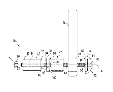
[0034] Referring initially to Figure 1 of the drawing, depicted
therein is a
first example bushing assembly insertion system 20 constructed in accordance
with, and embodying, the principles of the present invention. Figure 1 further
illustrates that the first example bushing assembly insertion system 20 may be
used to insert an example bushing assembly 22 into an example housing
opening 24 defined by an example structural member 26. Figure 1 further
illustrates that the example bushing assembly 22 defines a bushing assembly
opening 28 sized and dimensioned to receive a shaft (not shown). The example
bushing assembly 22 and structural member 26, including the housing opening
24, are or may be conventional and will not be described herein beyond that
extent helpful for a complete understanding of the construction and operation
of
the first example bushing assembly insertion system 20.
[0035] As shown in figures 1 and 2, the first example bushing
assembly
insertion system 20 comprises a brace assembly 30, an actuator assembly 32,
and a drive plate 34. The example brace assembly 30 comprises a brace rod 40,
an anchor member 42, and a brace nut 44. At least a portion of the example
brace rod 40 is arranged to extend through bushing assembly opening 28 in the
bushing assembly 22 and the housing opening 24 in the structural member 26 to
support the brace nut 44, the actuator assembly 32, the drive plate 34 on a
first
side of the housing opening 24 and the anchor member 42 on a second side of
the housing opening 24. So arranged, operation of the actuator assembly 32
acts on the bushing assembly 22 through the drive plate 34 to force the
bushing
assembly 22 into the bushing assembly opening 24. The example brace
assembly 30 engages the structural member 26 to prevent the actuator assembly
32 from displacing itself away from the structural member 26 during operation
of
the actuator assembly 32.
- 7 -
Date Recue/Date Received 2021-08-26
Ref. No. P220172ca
[0036] Given the foregoing general understanding of the
construction and
operation of the first example bushing assembly insertion system 20, the
details
of construction and operation of the first example bushing assembly insertion
system 20 of the present invention will now be described.
[0037] The example brace rod 40 defines a first rod end 50 and a
second
rod end 52, and an outer surface 54 of the example brace rod 40 is threaded at
least adjacent to the first rod end 52 and to the second rod end 54. The
example
brace rod 40 as depicted is threaded along its entire length, but only a
portion of
the brace rod 40 need be threaded as will become apparent from the following
discussion. The example brace rod 40 defines a brace rod axis 56.
[0038] The example anchor member 42 defines an anchor cavity 60 and
an anchor edge surface 62. The anchor cavity 60 defines an anchor cavity
spacing portion 64 and an anchor cavity threaded portion 66. The anchor cavity
threaded portion 66 is sized and dimensioned to receive the threaded outer
surface 54 of the brace rod 40 adjacent to the first rod end 50. Accordingly,
axial
rotation of the brace rod 40 and anchor member 42 relative to each other about
the brace rod axis 56 with the threaded outer surface 54 within the anchor
cavity
threaded portion 66 prevents displacement of the anchor member 42 relative to
the brace rod 40 along the brace rod axis 56 under predetermined tension loads
exerted by the actuator assembly 32.
[0039] The example brace nut 44 is or may be conventional and
defines
an external nut surface 70 and an internal threaded nut opening 72. The
internal
threaded nut opening 72 is sized and dimensioned to receive the threaded outer
surface 54 of the brace rod 40 adjacent to the second rod end 52. Accordingly,
axial rotation of the brace rod 40 and brace nut 44 relative to each other
about
- 8 -
Date Recue/Date Received 2021-08-26
Ref. No. P220172ca
the brace rod axis 56 with the threaded outer surface 54 within the internal
threaded nut opening 72 prevents displacement of the brace nut 44 relative to
the brace rod 40 along the brace rod axis 56 under predetermined tension loads
exerted by the actuator assembly 32. The example external nut surface 50 is a
hex surface but other surface configurations may be used.
[0040] The example actuator assembly 32 comprises an actuator
housing
80 and an actuator drive member 82. The example actuator assembly 32 is or
may be conventional and will be described herein only to that extent helpful
for a
complete understanding of the construction and operation of the first example
bushing assembly insertion system 20. The example actuator housing 80
defines an actuator housing opening 84, and the example actuator drive member
82 defines an actuator drive member opening 86. The example drive member 82
defines a drive surface 88. Operation of the example actuator assembly 32
causes displacement of the example actuator drive member 82 relative to the
actuator housing 80. The example actuator assembly 32 may be operated using
an electrical drive system, pneumatic drive system, hydraulic drive system, or
any other appropriate drive system. The drive system used to supply power to
the example actuator system 32 is or may be conventional and is not depicted
in
the drawing for simplicity and clarity.
[0041] The example drive plate 34 defines a first drive plate
surface 90, a
second drive plate surface 92, and a drive plate opening 94. The example drive
plate opening 94 defines a drive plate opening first portion 96 and a drive
plate
opening second portion 98. The drive plate opening 94 extends between the
first
drive plate first surface 90 and the second drive plate second surface 92.
[0042] As perhaps best shown in Figure 2, the example brace rod 40
is
sized and dimensioned such that the example brace rod 40 may be arranged to
- 9 -
Date Recue/Date Received 2021-08-26
Ref. No. P220172ca
extend through the actuator housing opening 84, the actuator drive member
opening 86, the adapter late opening 94, and the bushing opening 28. Figure 2
further illustrates that the example brace rod 40 is sized and dimensioned to
extend through the anchor cavity spacing portion 64 of the anchor cavity 60.
And
as described above, the anchor rod 40 is further sized and dimensioned such
that to be threaded into the anchor cavity threaded portion 66 and at least
partly
into the internal nut threaded opening 72. As arranged in Figure 2, the rod
axis
56 of the brace rod 40 defines a longitudinal axis of the first example
bushing
assembly insertion system 20.
[0043] Figures 3-11 illustrate an example method of using the first
example bushing assembly insertion system 20. Initially, as shown in Figure 3,
the anchor cavity threaded portion 66 is engaged with the external surface 54
of
the brace rod 40 to fix a position of the anchor member 42 relative to the
brace
rod 40. The brace rod 40 is then arranged such that the brace rod 40 extends
through the housing opening 24 with the axis 56 of the brace rod 40
substantially
aligned with a longitudinal axis of the housing opening 24. At this point, the
anchor edge 62 defined by the anchor member 42 is in contact with the
structural
member 26 around the housing opening 24.
[0044] Next, as shown in Figure 4 the bushing assembly 22 is
arranged
such that the brace rod 40 extends through the bushing opening 28 defined by
the bushing assembly 22 with the axis 56 of the brace rod 40 substantially
aligned with a longitudinal axis of the bushing assembly 22.
[0045] As shown in Figure 5, the drive plate 34 is next arranged
such that
the brace rod 40 extends through the drive plate opening 94 and the drive
plate
second surface 92 is in contact with the bushing assembly 22. In this
position, a
longitudinal axis of the drive plate 34 is substantially aligned with the
brace rod
- 10 -
Date Recue/Date Received 2021-08-26
Ref. No. P220172ca
axis 56.
[0046] As shown in Figure 6, the actuator assembly 32 is next
arranged
such that the brace rod 40 extends through the actuator housing opening 84 and
the actuator drive member opening 86. At this point, the drive surface 88 of
the
actuator drive member 82 is in contact with the drive plate first surface 92.
With
the actuator assembly 32 so arranged, a longitudinal axis of the actuator
assembly 32 is substantially aligned with the brace rod axis 56.
[0047] Figure 7 illustrates that the brace nut 44 is next arranged
such that
the brace rod 40 engages the internal threaded opening 72 of the brace nut 44.
Axial rotation of the brace nut 44 relative to the brace rod 40 displaces the
brace
nut 44 along the axis 56 of the brace rod 40 until the brace nut engages the
actuator housing 80. At this point, the brace assembly 30 is formed, and a
distance between the brace nut 44 and the anchor member 42 is substantially
fixed. When the brace assembly 30 is formed, the first example bushing
assembly insertion system 20 is formed.
[0048] With the brace assembly 30 formed as described above,
operation
of the actuator assembly 32 causes the actuator member 82 to be displaced
away from the actuator housing 80 along the rod axis 56. The actuator member
82 acts on and displaces the drive plate 34 which in turn acts on and
displaces
the bushing assembly 22. The brace assembly 30 prevents movement of the
anchor member 42 relative to the structural member 26, so operation of the
actuator assembly 32 forces the bushing assembly 22 into the housing opening
24 defined by the structural member 26 as shown by a comparison of Figures 7
and 8.
[0049] The actuator assembly 32 defines a maximum "throw" distance
that
-11 -
Date Recue/Date Received 2021-08-26
Ref. No. P220172ca
the drive member 82 may be forced out of the actuator housing 80. If the throw
distance is insufficient to fully drive the bushing assembly 22 into the
housing
opening, the actuator assembly 32 may be turned off and the actuator housing
80 may be displaced towards the bushing assembly 22 as shown in Figure 9.
The brace nut 44 may be then rotated such that brace nut 44 is displaced along
the brace rod 40 until the brace nut 44 contacts the housing as shown in
Figure
10.
[0050] The actuator assembly 32 may then be operated to drive the
bushing assembly 22 into the bushing assembly opening 24 until the bushing
assembly comes into contact with the anchor plate 42 as shown in Figure 11. At
this point, the anchor cavity spacing portion 64 defined by the anchor plate
42 is
sized and dimensioned such that the bushing assembly 22 extends out of the
housing opening 24 by a desired predetermined distance D as shown in Figure
12. Accordingly, the anchor plate 42 is configured to stop further movement as
soon as the bushing assembly 22 is a desired position relative to the bushing
assembly opening 24.
[0051] Referring now to Figure 13 of the drawing, depicted therein
is a
second example bushing assembly insertion system 120 constructed in
accordance with, and embodying, the principles of the present invention.
Figure
13 illustrates that the first example bushing assembly insertion system 120
may
be used to insert an example bushing assembly 122 into an example housing
opening 124 defined by an example structural member 126. The example
bushing assembly 122 and structural member 126, including the housing opening
124, are or may be conventional and will not be described herein beyond that
extent helpful for a complete understanding of the construction and operation
of
the second example bushing assembly insertion system 120.
- 12 -
Date Recue/Date Received 2021-08-26
Ref. No. P220172ca
[0052] The second example bushing assembly insertion system 120
comprises a brace assembly 130, an actuator assembly 132, and a drive plate
134. The example brace assembly 130 comprises a brace rod 140, an anchor
member 142, and a brace nut 144. During use of the second example bushing
assembly insertion system 120, at least a portion of the example brace rod 140
is
arranged to extend through a bushing assembly opening (not shown) in the
bushing assembly 122 and the housing opening 124 in the structural member
126 to support the brace nut 144, the actuator assembly 132, the drive plate
134
on a first side of the housing opening 124 and the anchor member 142 on a
second side of the housing opening 124. So arranged, operation of the actuator
assembly 132 acts on the bushing assembly 122 through the drive plate 134 to
force the bushing assembly 122 into the bushing assembly opening 124. The
example brace assembly 130 engages the structural member 126 to prevent the
actuator assembly 132 from displacing itself away from the structural member
126 during operation of the actuator assembly 132.
[0053] The example brace rod 140 and brace nut 144 are or may be the
same as the example brace rod 40 and brace nut 44 described above and will
not be described herein again in detail.
[0054] The example anchor member 142 defines an anchor cavity 160
and
an anchor edge 162. The anchor cavity 160 defines an anchor cavity spacing
portion 164 and an anchor cavity threaded portion 166. The anchor cavity
threaded portion 66 is sized and dimensioned to receive the threaded outer
surface of the brace rod 140 adjacent to the first rod end. The example anchor
cavity threaded portion 166 further allows the brace rod 140 to extend out of
the
anchor cavity 160 as shown in Figure 13. Axial rotation of the brace rod 140
and
anchor member 142 relative to each other about a brace rod axis prevents
displacement of the anchor member 142 relative to the brace rod 140 along the
- 13 -
Date Recue/Date Received 2021-08-26
Ref. No. P220172ca
brace rod axis under predetermined tension loads exerted by the actuator
assembly 132.
[0055] The second example bushing assembly insertion system 120 is
otherwise used in a manner similar to that of the first example bushing
assembly
insertion system 20 described above.
[0056] Referring now to Figure 14 of the drawing, depicted therein
is a
third example bushing assembly insertion system 220 constructed in accordance
with, and embodying, the principles of the present invention. Figure 14
illustrates
that the first example bushing assembly insertion system 220 may be used to
insert an example bushing assembly 222 into an example housing opening 224
defined by an example structural member 226. The example bushing assembly
222 and structural member 226, including the housing opening 224, are or may
be conventional and will not be described herein beyond that extent helpful
for a
complete understanding of the construction and operation of the third example
bushing assembly insertion system 220.
[0057] The third example bushing assembly insertion system 220
comprises a brace assembly 230, an actuator assembly 232, and a drive plate
234. The example brace assembly 230 comprises a brace rod 240, an anchor
member 242, a first brace nut 244, and a second brace nut 246.
[0058] During use of the third example bushing assembly insertion
system
220, at least a portion of the example brace rod 240 is arranged to extend
through a bushing assembly opening (not shown) in the bushing assembly 222
and the housing opening 224 in the structural member 226 to support the brace
nut 244, the actuator assembly 232, the drive plate 234 on a first side of the
housing opening 224 and the anchor member 242 on a second side of the
- 14 -
Date Recue/Date Received 2021-08-26
Ref. No. P220172ca
housing opening 224. So arranged, operation of the actuator assembly 232 acts
on the bushing assembly 222 through the drive plate 234 to force the bushing
assembly 222 into the bushing assembly opening 224. The example brace
assembly 230 engages the structural member 226 to prevent the actuator
assembly 232 from displacing itself away from the structural member 226 during
operation of the actuator assembly 232.
[0059] The example brace rod 240 and brace nut 244 are or may be the
same as the example brace rod 40 and brace nut 44 described above and will
not be described herein again in detail.
[0060] The example anchor member 242 defines an anchor cavity 260
and
an anchor edge 262. The anchor cavity 260 defines an anchor cavity spacing
portion 264 and an anchor cavity through portion 266. The anchor cavity
through
portion 266 is sized and dimensioned to allow the threaded outer surface of
the
brace rod 240 adjacent to the first rod end to extend out of the anchor cavity
260
as shown in Figure 14. Axial rotation of the brace rod 240 relative to the
first
brace nut 244 and the second brace nut 246 about a brace rod axis prevents
displacement of the anchor member 242 relative to the brace rod 240 along the
brace rod axis under predetermined tension loads exerted by the actuator
assembly 232.
[0061] The third example bushing assembly insertion system 220 is
otherwise used in a manner similar to that of the first example bushing
assembly
insertion system 20 described above.
[0062] Referring now to Figure 15 of the drawing, depicted therein
is a
fourth example bushing assembly insertion system 320 constructed in
accordance with, and embodying, the principles of the present invention.
Figure
- 15 -
Date Recue/Date Received 2021-08-26
Ref. No. P220172ca
15 further illustrates that the fourth example bushing assembly insertion
system
320 may be used to insert an example bushing assembly 322 into an example
housing opening 324 defined by an example structural member 326. Figure 15
further illustrates that the example bushing assembly 322 defines a bushing
assembly opening 328 sized and dimensioned to receive a shaft (not shown).
The example bushing assembly 322 and structural member 326, including the
housing opening 324, are or may be conventional and will not be described
herein beyond that extent helpful for a complete understanding of the
construction and operation of the fourth example bushing assembly insertion
system 320.
[0063] Bushing assemblies such as the example bushing assembly 322
are sold in numerous shapes and sizes. The example bushing assembly 322
defines a first end configuration 322a and a second end configuration 322b.
The
end configurations 322a and 322b differ for differing bushing assemblies.
[0064] As shown in Figure 1, the fourth example bushing assembly
insertion system 320 comprises a brace assembly 330, an actuator assembly 32,
and a drive plate 334. The example brace assembly 330 comprises a brace rod
340, an anchor member 342, and a brace nut 344. At least a portion of the
example brace rod 340 is arranged to extend through bushing assembly opening
328 in the bushing assembly 322 and the housing opening 324 in the structural
member 326 to support the brace nut 344, the actuator assembly 32, the drive
plate 334 on a first side of the housing opening 324 and the anchor member 342
on a second side of the housing opening 324. So arranged, operation of the
actuator assembly 32 acts on the bushing assembly 322 through the drive plate
334 to force the bushing assembly 322 into the bushing assembly opening 324.
The example brace assembly 330 engages the structural member 326 to prevent
the actuator assembly 32 from displacing itself away from the structural
member
- 16 -
Date Recue/Date Received 2021-08-26
Ref. No. P220172ca
326 during operation of the actuator assembly 32.
[0065] Given the foregoing general understanding of the
construction and
operation of the fourth example bushing assembly insertion system 320, the
details of construction and operation of the fourth example bushing assembly
insertion system 320 of the present invention will now be described.
[0066] The example brace rod 340 defines a first rod end 350 and a
second rod end 352, and an outer surface 354 of the example brace rod 340 is
threaded at least adjacent to the first rod end 352 and to the second rod end
354.
The example brace rod 340 as depicted is threaded along its entire length, but
only a portion of the brace rod 340 need be threaded as will become apparent
from the following discussion. The example brace rod 340 defines a brace rod
axis 356.
[0067] The example anchor member 342 defines an anchor cavity 360
and
an anchor edge surface 362. The anchor cavity 360 defines an anchor cavity
recess portion 364 and an anchor cavity threaded portion 366. The anchor
cavity
threaded portion 366 is sized and dimensioned to receive the threaded outer
surface 354 of the brace rod 340 adjacent to the first rod end 350.
Accordingly,
axial rotation of the brace rod 340 and anchor member 342 relative to each
other
about the brace rod axis 356 with the threaded outer surface 354 within the
anchor cavity threaded portion 366 prevents displacement of the anchor member
342 relative to the brace rod 340 along the brace rod axis 356 under
predetermined tension loads exerted by the actuator assembly 32. The anchor
cavity recess portion 364 is adapted to receive the second end 322b of the
bushing assembly 322.
[0068] The example brace nut 344 is or may be conventional and
defines
an external nut surface 370 and an internal threaded nut opening 372. The
- 17 -
Date Recue/Date Received 2021-08-26
Ref. No. P220172ca
internal threaded nut opening 372 is sized and dimensioned to receive the
threaded outer surface 354 of the brace rod 340 adjacent to the second rod end
352. Accordingly, axial rotation of the brace rod 340 and brace nut 344
relative
to each other about the brace rod axis 356 with the threaded outer surface 354
within the internal threaded nut opening 372 prevents displacement of the
brace
nut 344 relative to the brace rod 340 along the brace rod axis 356 under
predetermined tension loads exerted by the actuator assembly 32. The example
external nut surface 350 is a hex surface but other surface configurations may
be
used.
[0069] The example actuator assembly 32 comprises an actuator
housing
380 and an actuator drive member 382. The example actuator assembly 32 is or
may be conventional and will be described herein only to that extent helpful
for a
complete understanding of the construction and operation of the fourth example
bushing assembly insertion system 320. The example actuator housing 380
defines an actuator housing opening 384, and the example actuator drive
member 382 defines an actuator drive member opening 386. The example drive
member 382 defines a drive surface 388 and a first connecting surface 388a.
Operation of the example actuator assembly 32 causes displacement of the
example actuator drive member 382 relative to the actuator housing 380. The
example actuator assembly 32 may be operated using an electrical drive system,
pneumatic drive system, hydraulic drive system, or any other appropriate drive
system. The drive system used to supply power to the example actuator system
32 is or may be conventional and is not depicted in the drawing for simplicity
and
clarity.
[0070] The example drive plate 334 defines a first drive plate
surface 390,
a second drive plate surface 392, and a drive plate opening 394. The example
drive plate 334 further defines a drive recess 398a and a connecting surface
- 18 -
Date Recue/Date Received 2021-08-26
Ref. No. P220172ca
398b. The example drive plate opening 394 defines a drive plate opening first
portion 396 and a drive plate opening second portion 398. The drive plate
opening 394 extends between the first drive plate first surface 390 and the
second drive plate second surface 392. The drive recess 398a on the drive
plate
334 is contoured to receive the first end configuration 322a of the bushing
assembly 322 as will be described in further detail below.
[0071] The second connecting surface 398b is configured to engage
the
first connecting surface 388a to allow the drive plate 334 to be detachably
attached to the actuator housing 380. The example first drive surface 388a is
internally threaded, and the example second drive surface 398b is externally
threaded, but other connecting systems for detachably attaching the drive
plate
334 to the actuator housing 380 may be used.
[0072] As perhaps best shown in Figure 15, the example brace rod 340
is
sized and dimensioned such that the example brace rod 340 may be arranged to
extend through the actuator housing opening 384, the actuator drive member
opening 386, the adapter late opening 394, and the bushing opening 328. Figure
15 further illustrates that the example brace rod 340 is sized and dimensioned
to
extend through the anchor cavity recess portion 364 of the anchor cavity 360.
And as described above, the anchor rod 340 is further sized and dimensioned
such that to be threaded into the anchor cavity threaded portion 366 and at
least
partly into the internal nut threaded opening 372. As arranged in Figure 15,
the
rod axis 356 of the brace rod 340 defines a longitudinal axis of the fourth
example bushing assembly insertion system 320.
[0073] The fourth example bushing assembly insertion system 320 is
used
in a manner similar to that of the first example bushing assembly insertion
system 20 described above. However, in the fourth example bushing assembly
- 19 -
Date Recue/Date Received 2021-08-26
Ref. No. P220172ca
insertion system 320, the actuator assembly 332 is reversed such that the
actuator drive member 382 engages the brace nut 344 and the actuator housing
380 supports the drive plate 334 as generally described above.
[0074] The example drive plate 334 and the example anchor member 342
are sold in a variety of configurations to accommodate a variety of
configurations
of bushing assemblies 322. In particular, the anchor cavity recess portion 364
defined by the anchor member 342 and the drive recess 398a defined by the
drive plate 334 are configured as necessary to accommodate a particular
bushing assembly 322 and further to locate the particular bushing assembly 322
in a desired position relative to the example structural member 326.
[0075] Referring now to Figures 16 and 17 of the drawing, depicted
therein
is a first example method of removing a bushing assembly 420 from a housing
cavity 422 of a housing 424 using an actuator assembly 426. As perhaps best
shown in Figure 20, the example bushing assembly 420 comprises a bushing
sleeve 430, bushing pin 432, and elastomeric material (not shown in Figure 20
for clarity) that supports the bushing pin 432 relative to the bushing sleeve
430.
The bushing assembly 420, housing cavity 422, and housing 424 are not per se
part of the present invention and are disclosed herein only to that extent
helpful
to a complete understanding of the present invention.
[0076] A first step of the first example method of removing the
bushing
assembly 420 from the housing cavity 422 is shown in Figures 16A and 16B. A
brace assembly 440 comprising a threaded rod 442 and a nut 444 is provided.
The threaded rod 442 is secured to a pullbar socket 450, and the pullbar
socket
450 is secured to the bushing pin 432 by a threaded pin 452. A receiver
assembly 460 is formed by assembling an extension tube 462, cylinder adapter
464, cylinder tube cap 466, and first and second snap rings 468. The receiver
- 20 -
Date Recue/Date Received 2021-08-26
Ref. No. P220172ca
assembly 460 is arranged over the pullbar socket 450 and with the tube cap 466
thereof in contact with (engaging) the housing 424.
[0077] An actuator assembly 444 is arranged between the receiver
assembly 460 and a nut 446 such that extension of the actuator assembly 444
acts on the nut and the receiver assembly 460 to displace the threaded rod 442
such that the bushing pin 432 is removed from the bushing assembly 420. The
bushing sleeve 430 and elastomeric material remains in the housing cavity 422
at this point. When assembled, the actuator assembly 444, nut 446, and
threaded rod 442 form a drive assembly in the form of the actuator assembly
426
for displacing the bushing pin 432 relative to the bushing assembly 420.
[0078] The user of a receiver assembly 460 comprising a separate
cylinder adapter 464 and cylinder tube cap 466 allows the receiver assembly
460
to be arranged in at least two configurations depending upon the specific
function
be performed. In the example depicted in Figure 16B, the receiver assembly 460
is in a long configuration. The tube cap 466 is sized and dimensioned relative
to
the structural housing member 420, the housing cavity 422, and the bushing
assembly 420 to allow at least a portion of the bushing assembly 420 to enter
the
extension tube 462 when removed from the housing cavity 422. In the first step
depicted in Figure 16, the bushing pin 432 and at least a portion of the
elastomeric material from the housing 420, leaving the bushing sleeve 430 and
perhaps a portion of the elastomeric material within the housing cavity 422.
[0079] A second step of the first example method of removing the
bushing
assembly 420 from the housing cavity 422 is shown in Figures 17A and 17B.
The threaded rod 442 is extended through an opening in the bushing assembly
420 formed by removal of the bushing pin 432 and secured to a sleeve remover
470. The pullbar socket 450 is secured to the bushing pin 432 by a threaded
pin
- 21 -
Date Recue/Date Received 2021-08-26
Ref. No. P220172ca
452. The receiver assembly 460 is arranged over the threaded rod 442 in
contact with the housing 426. The actuator assembly 444 is arranged between
the receiver assembly 460 and a nut 446 such that extension of the actuator
assembly 444 acts on the nut and the receiver assembly 460 to displace the
threaded rod 442 such that the sleeve remover forces the bushing sleeve 430
(and the elastomeric material within the bushing sleeve 430) from the housing
cavity 422.
[0080] Again, the user of a receiver assembly 460 comprising a
separate
cylinder adapter 464 and cylinder tube cap 466 allows the receiver assembly
460
to be arranged in at least two configurations depending upon the specific
function
be performed. In the example depicted in Figure 17B, the receiver assembly 460
is in a short configuration. As described above, the tube cap 466 is sized and
dimensioned relative to the structural housing member 420, the housing cavity
422, and the bushing assembly 420 to allow at least a portion of the bushing
assembly 420 to enter the extension tube 462 when removed from the housing
cavity 422. The sleeve remover 470 is sized and dimensioned relative to
bushing sleeve 430 and the housing cavity 422 in the the structural member 420
to engage the bushing sleeve 430 and enter the cavity 422 when the sleeve 430
is removed. In the second step depicted in Figure 16, the housing sleeve 430
and any remaining portion of the elastomeric material from is removed from the
housing 420. At this point, the entire bushing assembly 420 has been removed.
[0081] Figure 18A illustrates an example configuration that allows
removal
of an old bushing assembly 420 or insertion of a new bushing assembly 420
relative to the housing cavity 422. The threaded rod 442 is secured to the
pullbar
socket 450, and the pullbar socket 450 is secured to the bushing pin 432 by a
threaded pin 452. A push adapter 480 is connected to the other end of the
bushing pin 432 by a threaded pin 452. The receiver assembly 460 is arranged
- 22 -
Date Recue/Date Received 2021-08-26
Ref. No. P220172ca
over the pullbar socket 450 in contact with the housing 424. An actuator
assembly 444 is arranged between the receiver assembly 460 and the nut 446
such that extension of the actuator assembly 444 acts on the nut and the
receiver assembly 460 to displace the threaded rod 442 such that the bushing
assembly 420 is pulled into the housing cavity 422. Figure 18B illustrates
removal of the entire spent bushing assembly 420 in one step, while Figure 18C
illustrates insertion of a new bushing assembly 420.
[0082] Figure 19 illustrates a first example adapter kit 490
comprising the
cylinder adapter 464, the cylinder tube cap 466, the extension tube 462, the
pullbar socket 450, the push adapter 480, and the sleeve remover 470 discussed
above. The threaded pins 452 and snap rings 468 are or may be conventional
and are also depicted in Figure 19. Figure 19 also illustrates a conventional
socket driver 492 that may be included in the example kit 490 and used to
drive
the threaded pins 452 as implicit in the discussion above. As generally
discussed above, Figure 20 illustrates an example bushing assembly 430 that
may be displaced using the adapter components of Figure 19. The example kit
490 may include two or more of the tube caps 466, sleeve removers 470, and
push adapters 480, where each of these components 466, 470, and/or 480 is
configured for a particular configuration of bushing assembly 420 and housing
cavity 422 adapted to accommodate that particular bushing assembly 420.
[0083] Figure 21 illustrates details of a second example adapter
kit 520
comprising an extension tube 532, a cylinder adapter 534, a cylinder tube cap
536, a cylinder tube cap adapter 538, a pullbar socket 450, and a push adapter
480. As with the first example kit 490, threaded pins 452 depicted in Figure
21
are sized and dimensioned to threadingly engage the pullbar socket 450 and the
push adapter 480 and are or may be conventional. As with the first example kit
490, the second example kit 520 may include two or more of the tube caps,
sleeve removers, and/or push adapters configured for a particular
configuration
- 23 -
Date Recue/Date Received 2021-08-26
Ref. No. P220172ca
of bushing assembly and housing cavity adapted to accommodate that particular
bushing assembly.
[0084] Figures 21- 23 ifflustrate that a first threaded surface
534a is
formed on the cylinder adapter 534, second and third threaded surfaces 532a
and 532b are formed on the extension tube 532, and a fourth threaded surface
536a is formed on the cylinder tube cap 536. The first and second threaded
surfaces 534a and 532a are sized and dimensioned to engage each other to
allow the cylinder adapter 534 to be detachably attached to the extension tube
532. The third and fourth threaded surfaces 432b and 536a are sized and
dimensioned to engage each other to allow cylinder tube cap 536 to be
detachably attached to the extension tube 532. The cylinder tube cap 536
defines a first mating surface 536b. The cylinder tube cap adapter 538 defines
a
second mating surface 538a. The first and second mating surfaces 436b and
538a are sized and dimensioned to engage each other to allow the cylinder tube
cap 536 to support the cylinder tube cap adapter 538.
[0085] The second example adapter kit 520 may otherwise be used in
the
same manner as the first example adapter kit 490 described above.
[0086] Figure 24 illustrates details of a third example adapter kit
550
comprising an extension tube 562, a cylinder adapter 564, a cylinder tube cap
466M, a cylinder tube cap adapter 568, a pullbar socket 450, and a push
adapter
480. Threaded pins 452 depicted in Figure 121 are sized and dimensioned to
threadingly engage the pullbar socket 450 and the push adapter 480 and are or
may be conventional. As with the first example kit 490 and second example kit
520, the third example kit 550 may include two or more of the tube caps,
sleeve
removers, and/or push adapters configured for a particular configuration of
bushing assembly and housing cavity adapted to accommodate that particular
bushing assembly.
-24 -
Date Recue/Date Received 2021-08-26
Ref. No. P220172ca
[0087] Figures 24-26 illustrate that a first engaging surface 564a
is formed
on the cylinder adapter 564, second and third engaging surfaces 562a and 562b
are formed on the cylinder adapter 562, and a fourth engaging surface 566a is
formed on the cylinder tube cap 566. The first and second engaging surfaces
564a and 562b are sized and dimensioned to engage each other to allow the
cylinder adapter 564 to be supported by the extension tube 562. The third and
fourth engaging surfaces 562a and 566a are sized and dimensioned to engage
each other to allow cylinder tube cap 566 to be supported by the extension
tube
562. The cylinder tube cap 566 further defines a fifth engaging surface 566b.
The cylinder tube cap adapter 568 defines a sixth mating surface 568a. The
fifth
and sixth mating surfaces 566b and 568a are sized and dimensioned to engage
each other to allow the cylinder tube cap 566 to support the cylinder tube cap
adapter 568.
[0088] Figures 24 and 26 further illustrate that magnets 470 are
supported
by at least one, and in the example kit 450, each of the extension tube 562,
the
cylinder adapter 564, the cylinder tube cap 566, the cylinder tube cap adapter
568, to detachably attach the various components as the kit is being arranged
for
use.
[0089] The third example adapter kit 550 may otherwise be used in
the
same manner as either of the first example adapter kit 490 and second example
adapter kit 520 described above.
- 25 -
Date Recue/Date Received 2021-08-26