Note: Descriptions are shown in the official language in which they were submitted.
41
=
CA 03129160 2021-08-05
I -
TRANSPORT CARRIER SYSTEM AND OVERHEAD CONVEYING DEVICE HAVING
TRANSPORT CARRIERS FOR TRANSPORTING HANGING ARTICLES
The invention relates to a transport carrier, a transport carrier system for
an overhead convey-
ing device, and an overhead conveying device having transport carriers for
transporting hang-
ing articles, as described in the preambles of claims 1, 17 and 19.
EP 3 028 960 Al discloses an overhead conveying device with a drive device and
transport
carriers movable thereby for transporting hanging articles. Each of the
transport carriers corn-
prises a base body and a supporting body, which is exchangeably mounted on the
base bod)
by means of a connecting device, having a completely enclosed receiving
opening for hook-
ing in at least one hanger of a hanging article. The drive device is designed
as a conveyor
chain, and each chain link forms the base body. The supporting bodies can be
exchanged
when the conveyor chain is closed (thus without opening up the conveyor
chain). The con-
fleeting device is designed as a plug connection. The plug connection
preferably comprises at
least one positive engagement element (locking lug) acting along an insertion
direction of the
plug connection. lithe plug connection is designed without an additional
positive engagement
element (locking lug), the supporting body is mounted on the base body only by
means of an
accordingly designed force fit, so that the exchanging operation can only be
carried out with
considerable effort. However, if the positive engagement element (locking lug)
is additionally
provided, it also has to absorb a weight force.
A comparable connecting device is disclosed in EP 3 050 828 Bl.
Generally, a "hanging article" is understood to mean an article, which is
transported sus-
pended, for example, by means of a hanger. Classic examples of hanging
articles are articles
of clothing suspended on clothes hangers, or transport bags for receiving
articles. In the pre-
sent context, "hanging article" stands in contrast to "lying article". Lying
articles are articles
being transported resting on a ground, which moves. In contrast, hanging
articles are sus-
pended below the transport carriers and/or the overhead conveying device.
Different embodiments of transport bags are known from DE 10 2004 018 569 Al,
DE 20 2017 106 993 Ul and WO 2018/130712 A2.
CA 03129160 2021-08-05
- 2 -
The object of the invention is to provide a transport carrier and a transport
carrier system for
an overhead conveying device with an improved connecting device between the
base body
and the supporting body. In particular, the supporting body is to be
exchangeable from the
base body with little effort and the simplest of technical means (tools). An
object of the inven-
tion is to provide an overhead conveying device having transport carriers for
transporting
hanging articles, which overhead conveying device can be adapted flexibly to
different hang-
ing articles and with little effort to changed requirements.
The object of the invention is achieved by the connecting device
- comprising a profile groove (first positive engagement element)
extending perpendicular
to the longitudinal axis in one of the base and supporting body connecting
sections, and a
profile projection (second positive engagement element) extending
perpendicular to the
longitudinal axis in one of the base and supporting body connecting sections,
- wherein the profile groove forms an undercut and an insertion opening
on the end side in
the direction of its longitudinal extension,
- wherein the profile projection comprises a profile web and a profile head
formed on the
profile web so as to expand the cross-section,
- wherein the profile projection can be inserted into the profile
groove via the insertion
opening in an insertion direction oriented perpendicular to the longitudinal
axis.
The connecting device comprises positive engagement elements of a positive
connection.
which are designed to complement each other and which mesh with each other.
when the sup-
porting body is mounted on the base body. In this regard, the positive
engagement elements
are formed to be rigid. Such rigid positive engagement elements are easy to
produce and the
connecting device can thus be produced in a cost-effective manner. Moreover,
rigid positive
engagement elements are more durable and less prone to defects due to frequent
exchanging
operations. The first positive engagement element (undercut profile groove) is
arranged in the
supporting body connecting section. and the second positive engagement element
(profile pro-
jection) is arranged in the base body connecting section. Conversely, the
first positive engage-
ment element (undercut profile groove) may be arranged in the base body
connecting section,
and the second positive engagement element (profile projection) may be
arranged in the sup-
porting body connecting section. In a preferred embodiment, the first positive
engagement el-
ement (undercut profile groove) and the second positive engagement element
(profile projec-
tion) are designed to have an essentially T-shaped cross-section. Otherwise,
the first positive
CA 03129160 2021-08-05
- 3 -
engagement element is a profile groove with a hollow-cylindrical undercut, and
the second
positive engagement element is a profile projection with a cylindrical profile
head. the diame-
ter of which is greater than the width of the profile web. In the context of
the invention, the
first positive engagement element and the second positive engagement element
may also form
different cross-sectional shapes.
Such a positive connection is also distinguished by the fact that the profile
projection can be
inserted into the profile groove by means of an insertion movement oriented
perpendicular to
the longitudinal axis. The insertion movement can be carried out with little
effort and without
additional tools. In particular, the positive connection can be established
regardless of whether
a particular joining force is reached or even exceeded, as it is the case for
force-fitted connect-
ing devices.
The positive engagement elements are also suitable for establishing a
connection between the
base body and the supporting body. which is loadable in particular with
respect to rotational
movements (about a vertical axis) and tensile stress (in the direction of a
vertical axis due to a
weight force). The connection is torsionally rigid and stable, even if the
supporting body is
exchangeably mounted on the base body by means of a single connecting device.
The connecting device allows quickly exchanging the supporting bodies, mostly
without addi-
tional tools.
Regardless of the configuration of the (different) supporting bodies. it is
possible to always
(universally) use the same base body configured in an optimized manner. While
the base body
can/has to model a variety of functions, the supporting bodies only assume one
single func-
tion.
Hence, the base body comprises the drive section, which comprises, for
example, at least one
guide roller, which abuts along a guide device of the overhead conveying in a
rollable man-
and at least one engagement section, which cooperates with a drive device of
the guide
roller and is acted upon by a driving force. The drive section may also be
equipped with a
stop, for example on a front side of the suspended support, with which stop a
first suspended
support runs against a stopper element, for example, and/or be equipped with a
stop, which is
provided, for example, on a rear side of the suspended support, with which
stop a second sus-
pended support runs against a first suspended support. Thus, the drive section
may realize the
,
' CA 03129160 2021-08-05
, =
- 4 -
functions "guiding the suspended support". "moving the suspended support"
and/or "position-
ing the suspended support". If the base body is additionally provided with an
identifying
means, the base body also takes on the function "identifying the suspended
support".
Regardless of their configurations. the supporting bodies, however,
exclusively take on the
function "receiving the hanging article".
Different supporting bodies. however, have a base body connecting section with
a uniform
(identical) first positive engagement element or second positive engagement
element.
Preferably, the base body is made of plastic and produced in one piece using
injection mold-
ing. Preferably, the supporting bodies are made of plastic and produced in one
piece using in-
jection molding. It may prove advantageous if the material properties of the
base body and the
supporting body differ. In particular, the plastic material of the base body
may have better me-
chanical properties. such as strength, impact toughness, deformability. and
the like, than the
plastic material of the supporting body/the supporting bodies used. Different
supporting bod-
ies may use different shapings and/or different material properties. For
example, in a first con-
figuration, the supporting body may be designed with a completely enclosed
receiving open-
ing, and in a second configuration, with a suspension hook. The supporting
body may have
different material properties in a first configuration and in a second
configuration. For exam-
ple, in a first configuration, the supporting body is designed to have a
higher material density
than the supporting body in a second configuration. Otherwise. the supporting
bodies ma
have different material properties in a first configuration with a suspension
hook, and/or the
supporting bodies may have different material properties in a second
configuration with a
completely enclosed receiving opening.
Depending on the transport requirements, only the supporting body is to be
exchanged while
the base body remains the same. If the hanging article is an article of
clothing suspended on a
clothes hanger, preferably, the supporting body in the second configuration
with a suspension
hook is used, and if the hanging article is a transport bag, preferably, the
supporting body in
the first configuration with a suspension hook having a completely enclosed
receiving open-
ing is used.
According to an embodiment of the invention, it is provided that the profile
groove is ar-
ranged in the supporting body connecting section, and the profile projection
is arranged in the
=
CA 03129160 2021-08-05
- 5 --
base body connecting section. The second positive engagement element (profile
projection)
tends to be smaller in size than the first positive engagement element
(profile groove), lithe
second positive engagement element (profile projection) is provided in the
base body connect-
ing section on the supporting body, the supporting bodies can be kept in a
more space-saving
manner as "
According to an advantageous embodiment, the transport carrier comprises a
front wall and a
rear wall, and the profile groove is formed by a profile groove extending from
the front wall
in the direction of the rear wall. The profile groove extends over a length
starting from the
front wall and preferably ends shortly before the rear wall. The supporting
body connecting
section, if the (undercut) profile groove is provided therein, or the base
body connecting sec-
tion, if the (undercut) profile groove is provided therein, has a greater
length compared to the
(undercut) profile groove, so that a material web remains on the profile
groove end adjoinino,
the rear wall. The profile groove end adjoining the front wall forms the
insertion opening.
which opens into the front wall. Thereby, an insertion direction for the
supporting body is
specified and an incorrect orientation of an exchanged supporting body is
prevented, which
would be disadvantageous especially in the case of asymmetrical suspended
supports. The
material web may generally also serve as an insertion limit (rigid stop),
against which the pro-
file web abuts when it has been inserted completely into the profile groove.
lithe profile groove is formed by a profile groove continuously opened toward
the supporting
body and along its longitudinal extension, a cross-sectional contour can be
produced easily. in
particular by injection molding. It also proves advantageous that after
removing a supporting
body via the opened profile groove itself the undercut is easily accessible,
and the profile
groove can be cleaned. This allows removing contaminants in the profile
groove, so that a re-
liable connection between the base body and supporting body is ensured even
after frequent
exchanging operations.
According to a particularly advantageous embodiment, it is provided that the
connecting de-
vice comprises mutually engageable locking elements, which are arranged and
formed such
that the base body and supporting body are arrested so as to be mutually
prevented from being
displaced in the longitudinal direction of the profile groove, if the
exchangeable supporting
body is mounted on the base body. The locking elements serve to arrest the
relative position
between the base body and the supporting body. In particular, the locking
elements become
CA 03129160 2021-08-05
- 6 -
effective when joining the base body and the supporting body. as they are
automatically
brought into engagement in the displacement movement.
Preferably, the locking elements comprise first locking elements which are
formed as elas-
tically resilient spring arms, each having a locking lug formed on a spring
clip, in one of the
base and supporting body connection sections on both sides of the profile
groove, and second
locking elements which are formed as locking openings arranged in one of the
base and sup-
porting body connection sections on both sides of the profile web. The first
locking elements
(flexible spring arms with one locking lug each) are arranged in the
supporting body connect-
ing section, and the second locking elements (locking openings) are arranged
in the base body
connecting section. Conversely, the first locking elements (flexible spring
arms with one lock-
ing lug each) may be arranged in the base body connecting section, and the
second locking el-
ements (locking openings) may be arranged in the supporting body connecting
section. The
spring arms are each elastically bendable in a bending direction extending
perpendicular to
their main direction of extension and are provided with locking lugs
protruding in the bending
direction on a spring clip. In the engagement position of the locking
elements, the locking
lugs are made to abut on an edging of the locking opening.
According to an embodiment, it is provided that the connecting device
comprises receiving
slots arranged in one of the base body and supporting body connecting sections
on both sides
of the profile web, each of which forms a support surface extending in the
insertion direction
of the supporting body and a locking opening arranged in a rear end region in
the insertion di-
rection of the supporting body. The receiving slots are arranged in the base
body connecting
section if the spring arms are provided in the supporting body connecting
section. Conversely.
the receiving slots may be provided in the supporting body connecting section
if the spring
arms are provided in the base body connecting section. If the supporting body
is moved rela-
to the base body in the insertion direction perpendicular to the longitudinal
axis, the
spring arms are, for example, bent inwards by the locking lugs resting on the
support surfaces
(in a sliding manner), and relax outwards, as soon as the locking lugs have
passed the edging
of the locking openings. If the locking lugs have an inclined shape, in
particular a sawtooth
shape, the supporting body can no longer be removed easily from the base body
against the
insertion direction, as the locking lugs enter into a positive connection with
the edging of the
locking opening.
CA 03129160 2021-08-05
=
- 7 -
The positive connection can be released by the spring arms being deflected in
a bending direc-
tion extending perpendicular to their main direction of extension such that
the locking lugs are
brought out of engagement with the edging of the locking openings.
Simultaneously, the sup-
porting body is moved towards the longitudinal axis, against the insertion
direction in a per-
pendicular direction.
For this purpose, the connecting device may have access channels, which the
locking open-
ings lead into. Preferably, a tool may be introduced into the access channels,
and with that, the
locking lugs may be levered out of the locking openings. A screwdriver
suffices as a tool.
An embodiment, in which the supporting body is equipped with a completely
enclosed receiv-
ing opening in a first configuration, or with a suspension hook in a second
configuration, is
also advantageous.
The configuration of different supporting bodies is a reaction to the
increasing requirements
for flexibility of storage and order-picking systems. Especially in e-commerce
in the textile
industry, an enormously high proportion of returns is to be expected.
Especially regarding re-
turns, it has proven advantageous if the returned articles are stored, sorted,
and picked with an
overhead conveyor system. The articles are manipulated as hanging articles.
hanging articles
are articles of clothing suspended on clothes hangers, or transport bags for
receiving articles.
The transport bags allow manipulating an almost unlimited range of articles.
The articles
(such as shoes, shirts, sweaters. T-shirts, accessories) are packed in
cardboard boxes, poly-
bags, and the like, for example.
In the light of this, supporting bodies can be used in a first configuration
with a suspension
hook or in a second configuration with a completely enclosed receiving
opening. supporting
bodies in a first configuration with a completely enclosed receiving opening
transport the sus-
pended transport bags (hanging bags), which accommodate the articles,
supporting bodies in a
second configuration with a suspension hook transport articles of clothing on
clothes hangers.
It may also prove advantageous if the supporting body additionally comprises
- a front side wall running essentially in parallel to the longitudinal
axis,
- a rear side wall running essentially in parallel to the longitudinal
axis,
- a lower side wall extending between the front side wall and rear side
wall,
CA 03129160 2021-08-05
a
- 8 -
- a receiving section for hanging a hanger of the hanging article,
formed by the front side
wall, rear side wall and lower side wall.
- an access channel leading into the receiving section. via which
access channel the hanger
of the hanging article is inserted into the receiving section, and
- is provided on the front side wall and rear side wall in lower wall
sections with guide
edges tapering towards each other in the direction toward the lower side wall.
and
- comprises a transport lock, which is arranged above the receiving
section with a vertical
distance, and forms a stop surface, which stop surface limits or impedes a
relative shift of
the hanger in the direction toward the transport lock.
Thereby. a "rising" of the hanger on a guide edge can be permitted to a
limited extent on the
one hand, and on the other hand, a "de-threading" of the hanger out of the
receiving section
via the access channel can be avoided. The transport of the hanging articles
on hangers can
thus be carried out in a reliable manner, and even at high transport speeds.
the loss of hanging
articles can be prevented.
The transport lock is primarily used for a supporting body in a second
configuration with a
suspension hook for transporting articles of clothing on clothes hangers.
Advantageous embodiments of the transport lock are described in the following
and are not
cited again at this point.
It may also prove advantageous if the base body comprises a receiving chamber
extending
perpendicular to the longitudinal axis and having an opening slot formed on
the end side in
the direction of its longitudinal extension, and an identifying means, in
particular a tran-
sponder, which can be inserted into the receiving chamber via the opening
slot. The receiving
chamber forms a receiving plane, which extends in the conveying direction of
the transport
carrier. Thus, the identifying means is also oriented transversely to the
conveying direction,
meaning to the side, with its main surface. Thus, reading errors can be
virtually precluded. An
overlap with other identifying means can also be avoided. The identifying
means preferably is
an RFID transponder (radio frequency identification). The identifying means
serves, for ex-
ample, for storing identification information regarding the transport carrier
and possibly re-
garding the hanging article transported by the transport carrier. Furthermore.
information re-
garding the transport path traveled and/or to be traveled may be stored in the
identifying
CA 03129160 2021-08-05
- 9 -
means configured as a data storage element. This information may be used to
control the ma-
terial flow.
According to an embodiment of the invention, it is provided that the receiving
chamber com-
prises a base opened toward the supporting body and an elastically resilient
spring arm, which
spring arm has a rest surface and protrudes in the direction toward the base,
so that the identi-
fying means, in particular the transponder, is supported on the rest surface
in the receiving
chamber and is held by means of the spring arm. The identifying means is not
arranged to be
permanently integrated in the base body but may be exchanged if needed
(defect. changeover
to new transponder technology).
It is also advantageous if the receiving chamber and the identifying means, in
particular the
transponder, are arranged between the drive section and the supporting body
connecting sec-
tion. Hence, a reliable reading operation is possible.
The object of the invention is also achieved in that the overhead conveying
device comprises
multiple transport carriers, wherein all transport carriers or at least some
of the transport carri-
ers comprise a supporting body for transporting a hanging articles, which
supporting body is
exchangeably mounted on the base body by means of a connecting device. Thus.
some of the
transport carriers may be formed in one piece, in which the base body and the
supporting
body are permanently (not releasably) connected. In particular, it is possible
keep the guide
device in an overhead conveying section, in which a drive device is not
provided, or the guide
device and drive device in an overhead conveying section. in which a drive
device is also pro-
vided, and the base bodies of the transport carriers unchanged. Only the
supporting bodies
have to be exchanged in order to be able to use the overhead conveying device
in a more ver-
satile manner. This modification can be carried out quickly and easily.
It is also advantageous if the transport carriers can be coupled to and
uncoupled from the
guide device or to/from the guide device and to/from the drive device. In
other words, the
drive section of the transport carriers is designed such that the transport
carrier (and not just
the supporting body) can be removed from the guide device or guide device and
drive device
without additional installation steps. Thereby, the overhead conveying device
can continue to
be operated, and exchanging or modifying the suspended supports requires only
a short down-
time.
CA 03129160 2021-08-05
- 10 -
The invention also relates to a transport carrier for an overhead conveying
device, and an
overhead conveying device having transport carriers for transporting hanging
articles, and an
unloading station for automatically unloading a transport bag, as described in
the preambles
of claims 20, 29, 30, 41 and 42.
Such a transport carrier for an overhead conveying device and such an overhead
conveying
device having transport carriers for transporting hanging articles are known,
for example.
from DE 10 2005 006 455A1 and WO 2017/109042 Al. The transport carriers
comprise a
base body and supporting bodies. The base body is provided with a drive
section, which may
cooperate with a guide device and/or a drive device of the overhead conveying
device. The
supporting body comprises a front side wall rising up, a rear side wall rising
up, a lower side
wall extending between the front side wall and rear side wall, and an upper
side wall extend-
ing between the front side wall and rear side wall, and lastly, a receiving
opening completely
enclosed by the side walls for hooking in a hanger of the hanging article. The
front side wall
and rear side wall each have a lower wall section and an upper wall section,
wherein the lower
wall sections are provided with guide edges tapering towards each other in the
direction to-
wards the lower side wall and end in the lower side wall.
These known transport carriers for an overhead conveying device can barely
stabilize the
hanging article during its transport, and the hanging article hanging freely
on the supporting
body begins to swing. This may even lead to the hanging article falling off
the supporting
body and/or hanging articles transported behind one another becoming entangled
at switches
and a fault correction being required. Also. a comparatively high frictional
wear occurs on the
lower side wall.
An object of the invention is to provide an improved transport carrier for an
overhead convey-
ing device. In particular, a safe transport of hanging articles should be
possible even at high
transport speeds. An object of the invention is to provide an improved
overhead conveying
device having transport carriers for transporting hanging articles. In
particular, a high availa-
bility of the overhead conveying device even at high transport speeds is to be
achieved.
The object of the invention is achieved in that the lower side wall comprises
a first rest section
and a second rest section, which are arranged on both sides of a midplane
spanned between
the front side wall and rear side wall and each offset at a distance from the
midplane, so that
for transporting the hanging article on the transport carrier, the hanger is
positioned between
the guide edges and can be supported on the first rest section and second rest
section.
CA 03129160 2021-08-05
- I I -
If the unloading of the hanging article (transport bag) on an automatic
unloading station de-
scribed below is also provided, the hanger may be positioned between the guide
edges and be
mounted (so as to slide) on the first rest section and second rest section,
when the hanging ar-
ticle (transport bag) is pivoted between a provisioning position and an
unloading position.
The (bent) hanger of the hanging article (clothes hanger or transport bag) is
thus supported on
more than one rest section, namely at least on a first rest section and second
rest section. The
first rest section and second rest section are arranged at a distance, which
is adapted to a cur-
vature radius of the hanger, in a transport plane extending transversely, in
particular perpen-
dicular, to the transport direction (of the hanging article) between the front
and rear side wall
and essentially vertically,.
Pivoting and wobbling movements of the hanging article suspended on a
transport carrier are
reduced to an extent, which allows a higher transport speed. Moreover, due to
the reduced
frictional wear, the transport carrier can be used for a longer time than is
possible in the prior
art.
It may also prove advantageous if the guide edges enclose between them an
opening angle of
less than 90 . This is more likely to prevent a "rising" of the hanger on the
guide edges than
with opening angles of more than 90 , as is common in the prior art. Thereby.
pivoting, and
wobbling movements can be additionally minimized. Likewise, a twisting of the
hanger
and/or the hanging article about a vertical axis can be reduced to a minimum.
This addition-
ally contributes to a stabilizing transport of the hanging article and/or a
reliable unloading of
the transport bag.
According to an advantageous embodiment, the guide edges each form a rounded
guide sur-
face. Thereby, a frictional wear on the guide edges can be minimized.
It also proves advantageous if the first rest section and second rest section
comprise edges ex-
tending in parallel to each other, whose minimum length is greater than a
minimum opening
width between the guide edges. Thereby, the support of the hanger on the first
rest section and
second rest section remains in place even upon a twisting of the hanger and/or
the hanging ar-
ticle about a vertical axis. If, on one hand, the hanger "rises" on a guide
edge, and the hanging
article inclines laterally relative to the vertical, the hanger can still be
supported on the guide
edge and at least one of the relevant first and second rest sections. If. on
the other hand, the
hanger "rises- but the hanging article hangs essentially parallel to the
transport plane or be
CA 03129160 2021-08-05
- 1") -
only slightly inclined laterally relative to the vertical, the hanger can be
supported on the
guide edge, the first rest section and second rest section.
If each of the edges is formed having a rounded rest surface, a particularly
good adaptation to
the curvature radius of the hanger and thus, an improved support of the hanger
on the first rest
section and second rest section is achieved.
In regard to the different advantageous embodiments in claims 25 to 28,
reference is made to
the above descriptions.
It may also prove advantageous if the supporting body additionally forms a
transport lock,
which is arranged above the receiving section with a vertical distance, and
forms a stop sur-
face, which stop surface limits or impedes a relative shift of the hanger in
the direction tovvard
the transport lock. Thereby, a "rising" of the hanger on a guide edge can be
permitted to a
limited extent on the one hand, and on the other hand, a "de-threading" of the
hanger out of
the receiving section via the access channel can be avoided. The transport of
the hanging arti-
cles on hangers can thus be carried out in a reliable manner, and even at high
transport speeds,
the loss of hanging articles can be prevented.
It is a particularly advantageous embodiment if the transport lock has an
elastically resilient
spring arm arranged on the rear side wall, which spring arm has a spring clip
and a stop ar-
ranged on the protruding end, wherein the stop protrudes into the access
channel and forms
the stop surface on its side wall facing the receiving section. The transport
carrier can be
loaded particularly easily, and the hanging article can be transported
particularly reliably. Ii
the transport carrier is to be equipped with a hanging article, the hanger is
supplied to the ac-
cess channel. By means of the weight force alone, the hanger pushes
(displaces) the spring
clip (out of a locked position) so far from the access channel in the
direction toward the rear
side wall (into a release position), that it can be moved downward in the
direction toward the
receiving section. As soon as the spring clip has been "released- by the
hanger, the spring clip
is moved out of the deflected release position back into the locked position.
In the locked po-
sition, a "rising" of the hanger on a guide edge is blocked by the stop. The
vertical distance
between the transport lock and the receiving section is preferably designed
such that even in
the highest hanger position, the hanger can be supported on the guide edge and
possibly on at
least one of the relevant first and second rest sections. If the hanging
article is to be removed
from the transport carrier, the hanger is pivoted about an axis extending in
the transport direc-
tion and moved out laterally of the receiving section.
CA 03129160 2021-08-05
- 13 -
The elastically resilient spring arm is made from plastic and is produced in
one piece with the
supporting body by means of injection molding. Likewise, however, it is also
possible that the
elastically resilient spring arm is produced separately from the supporting
body, preferably
from metal, and the supporting body is produced separately from the spring arm
by means of
injection molding. The spring arm is connected to the supporting body on the
rear side wall.
for example by means of a positive and/or force-fitted connection. A
materially bonded con-
nection is also possible. The elastically resilient spring arm forms a flat
spring clamped on
one side.
According to a further embodiment. it may be provided that the rear side wall
and the spring
clip comprise guide elements, which can be brought into engagement with each
other. Ac-
cording to a possible embodiment, the spring clip may be provided with a first
guide element
and a second guide element. Preferably, the first guide element and second
guide element pro-
ject from the spring clip in the direction toward the rear side wall. If the
first guide element
and second guide element are provided, they can, on one hand, be located
opposite each other
and be arranged symmetrically relative to a longitudinal axis of the spring
clip. If the first
guide element and second guide element are provided, they can, on the other
hand, be located
opposite each other and be arranged so as to be offset from each other in the
direction of a
longitudinal axis of the spring clip. According to a possible embodiment, the
first guide ele-
ment and second guide element may be arranged in the end region of the spring
clip and ex-
tend at maximum over a third of the length of the spring clip. Specifically,
the first guide ele-
ment and second guide element form guide projections. According to a possible
embodiment,
the first guide element and second guide element may be arranged in the center
and end re-
gion of the spring clip and extend at least over a third of the length of the
spring clip.
According to a possible embodiment, the spring clip may, however, also be
provided with a
single guide element. Specifically, the guide element forms a guide pin.
According to a possible embodiment. the rear side wall may be provided with a
first guide el-
ement and a second guide element. The first guide element of the spring clip
and the first
guide element of the rear side wall are designed to be complementary.
Likewise, the second
guide element of the spring clip and the second guide element of the rear side
wall are de-
signed to be complementary. If the first/second guide element of the spring
clip are formed by
CA 03129160 2021-08-05
- 14 -
guide projections, the first/second guide element oldie rear side wall is
formed by guide re-
cesses. If the guide element of the spring clip is formed by a guide pin, the
guide element of
the rear side wall is formed by a guide bore.
If the spring clip is provided with a single guide element and the rear side
wall is provided
with a single guide element, the guide element of the spring clip and the
guide element of the
rear side wall are designed to be complementary.
In particular, it proves advantageous if the first/second guide elements
engage with each other
not only in the release position but also in the locked position of the spring
clip, and thereby.
the spring clip is supported laterally in the locked position/release position
by the guide dc-
ment(s) on the rear side wall.
In particular, it proves advantageous if the stop forms the first/second guide
element, which
are arranged on the spring clip.
It may also prove advantageous if the transport lock has an elastically
resilient first spring arm
arranged on the front side wall, which first spring arm a spring clip and a
stop arranged on the
protruding end, and an elastically resilient second spring arm arranged on the
rear side wall.
which second spring arm has a spring clip and a stop arranged on the
protruding end, wherein
the stops each protrude into the access channel and form the stop surfaces on
a side wall fac-
ing the receiving section. According to this embodiment. the hanger is first
transferred via the
access channel to the elastically resilient first spring arm and elastically
resilient second
spring arm, which are consequently pushed apart as a result of the weight
force of the hanger.
By means of the weight force alone, the hanger pushes (displaces) the spring
clip of the first
spring arm (out of a locked position) so far from the access channel in the
direction toward the
front side wall (into a release position), and pushes (displaces) the spring
clip of the second
spring arm (out of a locked position) so far from the access channel in the
direction toward the
rear side wall (into a release position) that it can be moved in the direction
toward the receiv-
ing section. As soon as the spring clips have been "released- by the hanger,
the spring clips
are each moved out of the deflected release position back into the locked
position. In the
locked position, a "rising- of the hanger on a guide edge is blocked by the
stops. The vertical
distance between the transport lock and the receiving section is preferably
designed such that
even in the highest hanger position, the hanger can be supported on the guide
edge and possi-
bly on at least one of the relevant first and second rest sections. If the
hanging article is to be
removed from the transport carrier, the hanger is pivoted about an axis
extending in the
CA 03129160 2021-08-05
- 15 -
transport direction and moved out laterally of the receiving section. It may
also prove advan-
tageous if the transport lock comprises a raised area arranged on the rear
side wall, which
raised area protrudes into the access channel and forms the stop surface.
According to this
embodiment, a raised area is provided, which is designed to be essentially
rigid, in contrast to
the above embodiments with an elastically resilient spring arm, or an
elastically resilient first
spring arm and an elastically resilient second spring arm. The raised area
forms an "interfer-
ing contour" in the access channel, impeding a relative shift of the hanger in
the direction to-
ward the transport lock. Thereby, a "rising" of the hanger on a guide edge can
be permitted to
a limited extent on the one hand, and on the other hand, a "de-threading" of
the hanger out of
the receiving section via the access channel can be hindered. The guide edge
and the raised
area run into each other (adjoin each other) and enclose an angle, in
particular an angle
smaller than 150 . Thereby, a hanger "rising" on a guide edge is reverted in
the direction of
movement at the stop surface.
The object of the invention is also achieved in that the overhead conveying
device comprises
a plurality of the transport carriers described above.
In this regard, the transport carriers may be formed in one piece, in which
the base body and
the supporting body are permanently (not releasably) connected. Otherwise, the
transport car-
riers may comprise a supporting body for transporting a hanging article, which
is exchangea-
bly mounted on the base body by means of a connecting device, as described
above. It proves
particularly advantageous that, by using the suspended support according to
the invention, the
hanging articles on the overhead conveying device can be driven or be
transported at a higher
transport speed by means of gravity. Thereby, a high transport capacity is
achieved. Moreo-
ver. faults while transporting the hanging articles can be largely prevented.
One object of the invention is to provide an improved unloading station for
automatic unload-
ing of hanging articles (in particular transport bags) suspended on transport
carriers. In partic-
ular, a reliable unloading operation and a high availability of the unloading
station is to be
achieved even at high unloading speeds.
The object of the invention is achieved in that the unloading device comprises
an actuation
device, by means of which the transport bag along with the bag body can be
tilted relative to
the transport carrier and about a tilting axis extending essentially in
parallel to the longitudinal
extension of the overhead conveying device between a provisioning position and
an unloading
CA 03129160 2021-08-05
- 16 -
position, wherein in the unloading position, the articles can be discharged
from transport bag
through the unloading opening.
By using the transport carrier described above, it is now possible that, in
the unloading posi-
tion of the transport bag, the (bent) hanger of the hanging article (the
transport bag) is sup-
ported on more than one rest section, namely on the first rest section and
second rest section.
Thus, a reliable automatic unloading operation is made possible.
For unloading an article from the transport bag
i) in one step, the bag body is adjusted from the transport position
(closed position) into
the loading and/or unloading position (opened position) by means of the
opening and closing
device, and
ii) in one step, the transport bag along with the bag body is tilted
relative to the transport
carrier and about a longitudinal axis extending essentially in parallel to the
longitudinal exten-
sion of the overhead conveying device from a provisioning position into an
unloading posi-
tion by means of the unloading device, whereby the articles are discharged
from the transport
bag through the unloading opening.
The discharge direction of the articles extends in a discharge plane extending
transversely to
the transport direction of the transport bag. The articles can hence be
transported across an
only very short discharge path, which significantly reduces the discharge time
as compared to
the unloading stations known from the prior art. Moreover, it is possible to
place a take-over
plane, onto which the article is to be discharged, essentially at the level of
the unloading open-
ing, such that a particularly gentle transfer of the article to the take-over
plane is possible. The
take-over plane is for example defined by a conveying device. The bag body can
be adjusted
into the unloading position prior to the tilting of the transport bag from the
provisioning posi-
tion into the unloading position, or the transport bag is already adjusted
from the provisioning
position into the unloading position into the unloading position during the
opening operation
of the bag body into the unloading position.
It is favorable for the opening and closing device to comprise an actuation
device for auto-
matic opening and closing of the bag body, by means of which actuation device
the frame can
be pivoted about an axis relative to the suspended support such that the bag
body can be ad-
justed between the transport position (closed position) and the loading and/or
unloading posi-
tion (opened position).
CA 03129160 2021-08-05
- 17 -
The bag body can be adjusted between the transport position and the loading
and/or unloading
position by means of the frame which is preferably present. This results in a
particularly sim-
ple structure of the transport bag. The opening and closing device can also be
designed partic-
ularly simply.
It also proves to be particularly advantageous if the actuation device
comprises a driver mech-
anism having
an inlet section aligned upstream in a transport direction of the transport
bag.
an outlet section aligned downstream in the transport direction of the
transport bag.
and
I 0 an unloading section arranged between the inlet section and the outlet
section, wherein
the inlet section forms a tilted guide track that can be brought into an
abutting contact with the
frame such that the frame is pivoted during the transport of the transport bag
into the unload-
ing station, whereby the bag body is adjusted from the transport position into
the loading
and/or unloading position.
The driver mechanism does not require a drive and is thus structured simply.
The inlet section
comprises a tilted guide track that can be brought into an abutting contact
with the frame such
that the frame is adjusted between different tilting positions and. in the
course of this. the bag
body is adjusted from the transport position into the loading and/or unloading
position. The
adjustment between the transport position and the loading and/or unloading
position can be
carried out very gently. The transport bag is handled with care. Moreover, the
continuous
opening operation of the bag body allows the articles to be centered in the
storage space.
which facilitates the discharge of the articles from the good container.
It is also advantageous if the unloading section forms an essentially
horizontal guide track that
can be brought into an abutting contact with the frame such that the frame is
held in the piv-
oted deflection position during the unloading operation, whereby the bag body
also remains in
the opened position.
The transport bag can be guided during its tilting movement. The guide track
extends in paral-
lel to the transport direction of the transport bag, as does a tilting axis.
It also proves to be advantageous if the outlet section forms a tilted guide
track that can be
brought into an abutting contact with the frame such that the frame is pivoted
during the
CA 03129160 2021-08-05
1 8 -
transport of the transport bag out of the unloading station, whereby the bag
body is adjusted
from the loading and/or unloading position into the transport position.
The outlet section comprises a tilted guide track that can be brought into an
abutting contact
with the frame such that the frame is adjusted between different tilting
positions and, in the
course of this, the bag body is adjusted from the loading and/or unloading
position (opened
position) into the transport position (closed position). The adjustment
between the loading
and/or unloading position and the transport position can be carried out very
gently. The
transport bag is handled with care.
It proves to be favorable if the overhead conveying device, for the transport
of the transport
bag into the unloading station and for the transport of the transport bag out
of the unloading
station, comprises transport carriers movable by means of a drive device or by
means of grav-
ity, wherein the transport carrier and the suspended support are coupled to
one another in an
articulated manner, whereby the suspended support is pivotable about an axis
extending es-
sentially in parallel to the overhead conveying device relative to the
transport carrier.
The transport carrier can be moved by means of a frictional drive or a form-
fit drive. An em-
bodiment in which the transport carriers can be moved autonomously by means of
a self-pro-
pulsion is also possible. The transport carriers can be transported to the
unloading station and
away from the unloading station very dynamically. which promotes a high
unloading perfor-
mance.
However, the transport carriers can also be transported by means of gravity if
the profile rail
on which the transport carriers are moved has a slope. This embodiment is
favorable where
capital costs are to be kept low.
It can also be provided that a locking device for arresting the transport
carrier during an un-
loading operation of the transport bag is allocated to the opening and closing
device of the un-
loading station.
The transport carrier is temporally arrested for unloading of the transport
bag. which allows
for an unwanted movement of the transport carrier and the transport bag in a
transport direc-
tion and/or transversely to the transport direction to be prevented during the
tilting movement
CA 03129160 2021-08-05
- 19 -
of the transport bag. The unloading process can also be carried out
particularly reliably for
large and/or heavy articles.
It is also possible that the opening and closing device of the unloading
station comprises a
guide device for laterally guiding the transport carrier during a transport
movement of the
transport carrier through the overhead conveying device for transporting the
transport bag into
the unloading station and for transporting the transport bag out of the
unloading station.
For unloading the transport bag, the transport carrier is guided laterally
which prevents un-
wanted tilting of the transport carrier about an axis extending in a transport
direction during
the tilting movement of the transport bag. The unloading process can also be
carried out par-
ticularly reliably for large and/or heavy articles.
An advantageous design is also possible if the actuation device of the
unloading device com-
prises a frame structure that can be tilted by means of a drive between an
initial position and
an actuation position about an axis extending in parallel to the transport
direction of the
transport bag and the actuation device of the opening and closing device is
mounted on the
frame structure.
The opening and closing device is moved together with the frame structure that
can be tilted
between the initial position and the actuation position. which allows for an
opening operation
of the bag body and the tilting operation of the transport bag to be carried
out simultaneously
and/or for a closing operation of the bag body and the back-tilting operation
of the transport
bag to be carried out simultaneously. The unloading operation can hence be
accelerated addi-
tionally. Moreover, the unloading operation can be carried out without
stopping of the
transport movement. However, in general, the transport speed of the transport
carriers and the
transport bag in the transport movement along the unloading station can vary.
For the purpose of better understanding of the invention, it will be
elucidated in more detail
by means of the figures below.
These show in a respectively very simplified schematic representation:
Fig. 1 an overhead conveying device for transporting hanging
articles, in a per-
spective view;
CA 03129160 2021-08-05
- 20 -
Fig. 2a an overhead conveying device with a guide device and drive
device for fric-
tional drive of the transport carriers, in a front view and partially in a sec-
tional view;
Fig. 2b an overhead conveying device with a guide device and drive
device for pos-
itive engagement drive of the transport carriers, in a front view and
partially
in a sectional view;
Fig. 2c an overhead conveying device with a guide device but
without a drive de-
vice for the transport carriers, in a lateral view;
Figs. 3a. 3b a transport bag with a bag body, Fig. 3a in the transport
position and Fig. 3b
in the loading position or unloading position (articles not depicted), in per-
spective views;
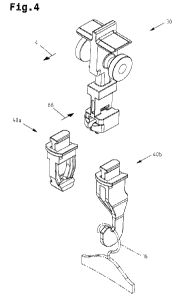
Fig. 4 a transport carrier system for an overhead conveying device
with a univer-
sally applicable base body and supporting bodies exchangeable by means of
a connecting device, in a first configuration with a completely enclosed re-
ceiving opening for transporting a transport bag (shown in Figs. 3a, 3b), and
in a second configuration with a suspension hook for transporting a clothes
hanger (only partially shown). in a perspective view:
Figs. 4a, 4b a supporting body with a first embodiment of a transport
lock in different
views;
Figs. 4c, 4d a supporting body with a second embodiment of a transport lock
in different
views;
Figs. 4e, 4f a supporting body with a third embodiment of a transport
lock in different
views;
Figs. 4g to 4i an overhead conveying device with a guide device, a
transport carrier with a
supporting body according to the embodiment in Figs. 4a. 4b, and a loading
station, with a process sequence for loading the transport carrier with a
hanger of a hanging article, in a lateral view;
CA 03129160 2021-08-05
- 21 -
Fig. 4j the overhead conveying device according to Fig. 4g, in a
front view and par-
tially in a sectional view;
Fig. 5a a first embodiment for a transport carrier with the base
body and supporting
body separated therefrom in a first configuration with a completely enclosed
receiving opening, in a first lateral view;
Fig. 5b the transport carrier according to Fig. 5a, in a second
lateral view;
Fig. 6a the transport carrier according to Fig. 5a, in a first
front view;
Fig. 6b the transport carrier according to Fig. 5a, in a second
front view;
Fig. 7a a transport carrier with the base body and supporting body
separated there-
from in a second configuration with a suspension hook, in a first lateral
view;
Fig. 7b the transport carrier according to Fig. 7a, in a second
lateral view;
Fig. 8a a second embodiment for a transport carrier with a base
body and support-
ing body permanently connected thereto in a first configuration with a corn-
pletely enclosed receiving opening, in a front view;
Fig. 8b a partial section of the transport carrier according to
Fig. 8a with the sup-
porting body, in an enlarged lateral view;
Fig. 8c a sectional representation through the front side wall;
Figs. 9 to 15 a sequence order of method steps for automatic unloading of
one of the
transport bags in an automated unloading station, in perspective views;
Fig. 16a a view onto the unloading device and a schematically shown
transport bag
according to Fig. 11, said transport bag being in a provisioning position,
partially in a sectional view;
Fig. 16b a view onto the unloading device and a schematically shown
transport bag
according to Fig. 12, said transport bag being in an unloading position, par-
tially in a sectional view.
CA 03129160 2021-08-05
- 22 -
First of all, it is to be noted that in the different embodiments described,
equal parts are pro-
vided with equal reference numbers and/or equal component designations. where
the disclo-
sures contained in the entire description may be analogously transferred to
equal parts with
equal reference numbers and/or equal component designations. Moreover, the
specifications
of location, such as at the top, at the bottom, at the side. chosen in the
description refer to the
directly described and depicted figure, and in case of a change of position.
are to be analo-
gously transferred to the new position.
Fig. I shows a section of an overhead conveyor device 1 with transport
carriers 2 for trans-
porting hanging articles 3 in a transport direction 4. Classic examples of
hanging articles 3 arc
articles of clothing suspended on clothes hangers, or transport bags for
receiving objects.
Fig. 1 shows the hanging articles 3 as transport bags. The hanging article 3
is suspended on
and below the transport carrier 2. A transport carrier 2 may also transport
more than one hang-
ing article 3. The transport bag can be loaded with an article 5. Preferably,
a single article 5 is
received in the transport bag. In general, more than one article 5 may also be
received in the
transport bag. The transport bag 2 can transport different articles 5, which
vary in their geom-
etry/dimension. The articles 5 are for example cardboard boxes, foil bags (so-
called "poly-
bags-) or the like. Such foil bags are predominantly used in the textile
industry and are for ex-
ample used for packaging T-shirts, shirts and the like.
According to the embodiment shown in Fig. 1, the overhead conveying device 1
comprises in
a transport section a guide device 10, a drive device 11. and the transport
carriers 2 movable
along the guide device 10 by means of the drive device 11. The guide device 10
is formed, for
example, on a profile rail 12.
As shown in more detail in Figs. 2a, 5a. 5b, 6a. 6b, the transport carriers 2
are moved by
means of a friction drive (drive device 11) according to the exemplary
embodiment shown.
The transport carrier 2 comprises a base body 30 yet to be described further,
which forms a
drive section 31. The drive section 31 may cooperate with the guide device 10
and drive de-
vice 11 (in this transport section). The drive section 31 comprises in
particular a (first)
roller 32 rotatably mounted on an axle, and a friction surface 33, the latter
of which can be
brought into frictional contact with an endlessly revolving friction belt 13
of the drive de-
vice 11. 'Me (second) roller 32 shown in the Figs. is optional and serves for
guiding the
transport carrier 2 at a switching point.
CA 03129160 2021-08-05
- 23 -
The transport carrier 2 is stored on the guide device 10 in a suspended manner
via the (first)
roller 32 and can be moved in the transport direction 4 by the friction drive.
According to an embodiment schematically shown in Fig. 2b, the transport
carriers 2 can be
moved by means of a positive engagement drive (drive device 11). The transport
carrier 2
comprises a base body 30 yet to be described further, which forms a drive
section 31. The
drive section 31 may cooperate with the guide device 10 and drive device 11
(in this transport
section). The drive section 31 comprises in particular a (first) roller 32
rotatably mounted on
an axle, and an engagement surface 34, the latter of which can come into
interlocking engage-
ment with one of multiple driver elements 14 on an endlessly revolving
friction belt 15 (drive
belt, drive chain and the like). The (second) roller 32 shown in the Figs. is
optional and serves
for guiding the transport carrier 2 at a switching point.
The transport carrier 2 is stored on the guide device 10 in a suspended manner
via the (first)
roller 32 and can be moved in the transport direction 4 by the positive
engagement drive. Such
an embodiment is described for example in DE 10 2005 006 455 Al.
A combination of a friction drive and a positive engagement drive is also
possible. Such an
embodiment is described for example in EP 2 121 489 Bl.
The described drive devices 12 are in no way to be understood restrictively,
but only show
different possibilities of how a driving force is transmitted from the drive
device 11 to the
drive section 31 of the transport carrier 2 (mounted so as to suspended on the
guide de-
vice 10), in order to move it (so as to be driven) on the guide device 10 in
the transport direc-
tion 4.
Fig. 2c shows the overhead conveying device 1 in a transport section. in which
a drive device
is not provided but only the guide device 10. The guide device 10 is formed.
for example, on a
profile rail 12 mounted in an inclined manner. In this case, the transport
carriers 2 (mounted
so as to be suspended on the guide device 10) are moved (not driven) on the
guide device 10
in the transport direction 4 by means of gravity and without a drive device.
The drive sec-
tion 31 may cooperate only with the guide device 10 (in this transport
section).
Figs. 3a, 3b show a suspended transport bag (also referred to as "hanging bag-
) with a possi-
ble embodiment of a bag body. Fig. 3a shows the transport position and Fig. 3b
shows an
CA 03129160 2021-08-05
- 24 -
opened position, which relates to the loading position if the transport bag is
to be loaded, or to
the unloading position if the transport bag is to be unloaded. The article 5
is not depicted in
these figures for the sake of clarity. Regarding the unloading station for
automatic unloading
of a transport bag and the different embodiments of a transport bag, the
detailed disclosure in
the Austrian patent application AT 520 517 A4 (A50320/2018) and A50059/2019 is
made the
subject matter of this disclosure.
The transport bag comprises a hanger 16, which can be hung in a receiving
opening 54 for
transporting the hanging article 3, which receiving opening 54 is provided on
a supporting
body 40a of the transport carrier 2 and is completely enclosed. The hanger 16
is preferably
fastened to an (optional) suspended support 16 in a rigid manner.
The suspended support 17 and the transport carrier 2 are coupled to one
another in an articu-
lated manner by means of a hinged connection. The hinged connection is formed
by the sup-
porting body 40a with the receiving opening 54 and the hanger 16.
According to a possible embodiment, it proves advantageous if the transport
bag is unloaded
at an automatic unloading station, as it is described, for example, in the
Austrian patent appli-
cation AT 520 517 A4 (A50320/2018) and below. To that end, it may be provided
in particu-
lar that the suspended support 17 and the transport carrier 2 are coupled to
one another in an
articulated manner by means of a hinged connection such that the suspended
support 17 is
pivotable relative to the transport carrier 2 about an axis 18 extending
essentially in parallel to
the guide device 10 (and/or essentially in parallel to the transport direction
4).
According to the embodiment shown, the transport bag comprises an (optional)
frame 19 and
a bag body, which is adjustable (optionally by means of the frame 19) between
a transport po-
sition (Fig. 3a) and a loading or unloading position (Fig. 3b).
The (optional) frame 19 is mounted so as to be pivotable on and relative to
the suspended sup-
port 17. about an axis 20 that is preferably oriented essentially
horizontally.
The bag body comprises
- a front wall 21 and a rear wall 22,
- a first side edge 23a and a second side edge 23b along the front wall
21 and rear wall 22,
CA 03129160 2021-08-05
- 25 -
- a loading and/or unloading opening 24 formed on a first side of the
bag body at least in
some regions between the front and rear wall 21, 22.
- a side wall stop 25 formed on a second side of the bag body at least in
some regions be-
tween the front and rear wall 21, 22, against which side wall stop 25 articles
5 can be
placed, and
- a storage space for storing the articles 5 between the front and rear
wall 21, 22.
In a preferred embodiment, the front wall 21 and rear wall 22 are cut from a
flexible (non-
rigid) material, in particular cut from a continuous length of textile, length
of film, a braid. a
knitted fabric, a woven fabric or the like.
The front wall 21 comprises a first front wall section 26a, a second front
wall section 26b and
a base plate 27. The base plate 27 is provided in the first front wall section
26a. In particular.
the first front wall section 26a comprises the base plate 27 and/or the first
front wall sec-
tion 26a forms the base plate 27. The base plate 27 is dimensionally stable
and is preferably
designed with a square shape. In general, it may also be rectangular.
The rear wall 22 comprises a first rear wall section 28a and a second rear
wall section 28b.
The first rear wall section 28a adjoins the first front wall section 26a, the
latter being provided
with the base plate 27. The rear wall 22 is formed with a lower rigidity
and/or dimensional
stability in the first rear wall section 28a than in the first front wall
section 26a. In other
words, the first front wall section 26a is designed to be more rigid and/or
more dimensionally
stable compared to the first rear wall section 28a.
As can be seen in Fig. 3a, the front wall 21 and rear wall 22 are approximated
to one another
in the transport position, and the article 5 (not shown) is held preferably
clamped by means of
the base plate 27 and the second rear wall section 28b. Additionally, the
article 5 rests on the
first rear wall section 28a. In its transport position, the bag body forms in
the first rear wall
section 28a a transport rest 29 extending between the first side edge 23a and
second side
edge 23b, which transport rest 29 comprises a transport rest surface slanting
in the direction of
CA 03129160 2021-08-05
- 26 -
the side wall stop 25 (thus extending inclined downwards). The transport rest
surface adjoins
the side wall stop 25.
As can be seen in Fig. 3b, the front wall 21 and rear wall 22 are moved away
from each other.
and the loading and/or unloading opening 24 is delimited by the front wall 21
and rear wall 22
and adjoins the first base plate 27 when the bag body is in one of the opened
positions, which
relates to the loading position if the transport bag is to be loaded, or to
the unloading position
if the transport bag is to be unloaded (loading and/or unloading position). In
the loading
and/or unloading position, the storage space is maximized in volume. According
to a pre-
ferred embodiment, both loading and unloading of the transport bag is carried
out via the
loading and unloading opening 24. In principle, loading can also be carried
out from above.
through the frame 19. However, unloading is carried out via the unloading
opening 24 accord-
ing to this embodiment, as well. Loading and/or unloading can be carried out
automatically or
manually.
As can be seen in Figs. 3a, 3b, the front wall 21 is mounted, with the second
front wall sec-
tion 26b, on a front cross strut of the frame 19 in an articulated manner
(first pivot bearing).
and the rear wall 22 is mounted, with the second rear wall section 28b, on a
rear cross strut of
the frame 19 in an articulated manner (second pivot bearing).
Figs. 2a, 2b, 4, 5a, 5b, 6a, 6b (supporting body in a first configuration with
a completely en-
closed receiving opening) and Figs. 7a, 7b (in a second configuration with a
suspension hook)
show different views of a transport carrier 2 for an overhead conveying
device, preferably for
the overhead conveying device 1 described above, which comprises a base body
30 and a sup-
porting body 40a. 40b exchangeably mounted by means of a connecting device 50
for trans-
porting a hanging article 3. Figs. 2a, 2b, 2c show the supporting body 40a in
the operation po-
sition mounted on the base body 30, and Figs. 5a, 5b, 6a, 6b show the
supporting body 40a in
the preparation position detached from the base body 30. The transport carrier
2 forms a lon-
gitudinal axis 51, which is, in particular, oriented vertically when the
transport carrier 2 is
stored in a suspended manner on the guide device 10.
The base body 30 is equipped with a drive section 31, which may cooperate with
a guide de-
vice 10 and/or with a drive device 11 of the overhead conveying device I. and
a supporting
body connecting section 52. The supporting body 40a comprises a base body
connecting sec-
CA 03129160 2021-08-05
- 27 -
tion 53 and, in a first configuration, a completely enclosed receiving opening
54. The support-
ing body 40b comprises a base body connecting section 53 and, in a second
configuration. a
suspension hook 55.
The connecting device 50 comprises a profile groove 60 (first positive
engagement element)
extending perpendicular to the longitudinal axis 51 in one of the base and
supporting body
connecting sections 52, 53, and a profile projection 61 (second positive
engagement element)
extending perpendicular to the longitudinal axis 51 in one of the base and
supporting body
connecting sections 52, 53.
According to a preferred embodiment, the profile groove 60 (first positive
engagement ele-
ment) is arranged on the base body 30 in the supporting body connecting
section 52, and the
profile projection 61 (second positive engagement element) is arranged on the
supporting
body connecting section 40a, 40b in the base body 53.
The profile groove 60 comprises an undercut 62, which forms an insertion
opening 63 on the
end side in the direction of its longitudinal extension. The profile
projection 61 comprises a
profile web 64 and a profile head 65 formed on the profile web 64 so as to
expand the cross
section. The profile projection 61 can be inserted into the profile groove 60
via the insertion
opening 63 in an insertion direction 66 (Fig. 4) oriented perpendicular to the
longitudinal
axis 51.
In a preferred embodiment, the undercut profile groove 60 and the profile
projection 61 are
designed having an essentially T-shaped cross-section.
As depicted exclusively in Fig. 5b, the transport carrier 2 comprises a front
wall 56 and a rear
wall 57. The undercut profile groove 60 is formed by a profile groove
extending from the
front wall 56 in the direction of the rear wall 57. The profile groove ends in
front of the rear
wall 57, so that a material web 67 remains.
The undercut profile groove 60 can additionally be formed by a profile groove
continuously
opened toward the supporting body 40a, 40b and along its longitudinal
extension.
According to a preferred embodiment, the connecting device 50 comprises
mutually engagea-
ble locking elements 68, 71, which are arranged and formed such that the base
body 30 and
supporting body 40a, 40b are arrested so as to be mutually prevented from
being displaced in
CA 03129160 2021-08-05
- 28 -
the longitudinal direction of the profile groove 60, if the exchangeable
supporting
body 40a, 40b is mounted on the base body 30, as can be seen in Fig. 2c
exclusively.
The locking elements comprise first locking elements 68, which are formed as
elastically re-
silient spring arms, each having a locking lug 70 formed on a spring clip 69.
in one of the
base and supporting body connection sections 52. 53 on both sides of the
profile groove 60.
The locking elements comprise second locking elements 71. which are formed as
locking
openings 72 arranged in one of the base and supporting body connection
sections 52, 53 on
both sides of the profile web 64.
According to a preferred embodiment, the first locking elements 68 (spring
arms with locking
lugs 70) are arranged on the base body 30 in the supporting body connecting
section 52, and
the second locking elements (locking openings 72) are arranged on the
supporting
body 40a, 40b in the base body connecting section 53.
According to a preferred embodiment, the connecting device 50 comprises
receiving slots 80
arranged in one of the base body and supporting body connecting sections 52.
53 on both
sides of the profile web 64, each of which forms support surfaces 81 extending
in the inser-
tion direction 66 of the supporting body 40a, 40b and a locking opening 72
arranged in a rear
end region in the insertion direction 66 of the supporting body 40a, 40b.
If the supporting body 40a, 40b is moved relative to the base body 30 in the
insertion direc-
tion 66 perpendicular to the longitudinal axis 51. the spring arms are, for
example, bent in-
wards by the locking lugs 70 resting on the support surfaces 81(in a sliding
manner), and re-
lax outwards, as soon as the locking lugs 70 have passed the edging of the
locking open-
ings 72. For example, sawtooth-like locking lugs 70 engage behind the edging
of the locking
openings 72.
The positive connection can be released by the spring arms being deflected in
a bending direc-
lion extending perpendicular to their main direction of extension such that
the locking lugs 70
are brought out of engagement with the edging of the locking openings 72.
Simultaneously.
the supporting body 40a, 40b is moved towards the longitudinal axis 51 against
the insertion
direction 66 in a perpendicular direction.
=
CA 03129160 2021-08-05
=
- 29 -
For this purpose, the connecting device may have access channels 82, which the
locking
openings 72 lead into. Preferably, a tool may be introduced into the access
channels 82, and
with that, the locking lugs 70 may be levered out of the locking openings 72.
As depicted, for example, in Figs 6a. 6b, 7a, 7b. the base body 30 may
comprise a receiving
chamber 85 extending perpendicular to the longitudinal axis 51 and having an
opening slot 86
formed on the end side in the direction of its longitudinal extension, and an
identifying
means 87. which can be inserted into the receiving chamber 85 via the opening
slot 86. The
identifying means 87 is preferably designed as an RFID transponder.
In particular, the receiving chamber 85 comprises a base opened toward the
supporting bod)
connecting section 52 and an elastically resilient spring arm 88 which has a
rest surface. and
which protrudes in the direction toward the base. The RFID transponder which
is inserted into
the receiving chamber 85 is supported on the rest surface and is held by the
spring arm 88.
The receiving chamber 85 and the identifying means 87 are arranged in a
transport carrier
identifying section 89 between the drive section 31 and the supporting body
connecting sec-
tion 52.
Fig. 4 shows a transport carrier system for an overhead conveying device,
preferably for the
overhead conveying device I described above. The transport carrier system
comprises
- a first supporting body 40a in a first configuration with a base body
connecting section 53
and a completely enclosed receiving opening 54 for transporting a hanging
article 3,
- a second supporting body 40b in a second configuration with a base
body connecting sec-
tion 53 and a suspension hook 55 for transporting a hanging article 3, and
- a universally applicable base body 31 with a drive section 31, which may
cooperate with
a guide device 10 and/or with a drive device 11 of the overhead conveying
device 1, and
75 a supporting body connecting section 52.
The first supporting body 40a or the second supporting body 40b in the second
configuration
may be mounted to the base body 30 so as to be exchangeable by means of the
connecting de-
vice 50 described above, in order to optionally form a transport carrier 2 in
a first configura-
tion with a completely enclosed receiving opening 54 for transporting a
hanging article 3 or a
transport carrier 2 in a second configuration with a suspension hook 55 for
transporting a
hanging article 3. The transport carrier 2 in the first configuration
preferably serves for
CA 03129160 2021-08-05
- 30 -
transport in a transport bag, wherein its hanger 16 is hung into the receiving
opening 54 (see
for example Fig. 3a). The transport carrier 2 in the second configuration
preferably serves for
transporting an article of clothing on a clothes hanger, wherein the hanger 16
of the clothes
hanger is hung on the suspension hook 55 (see Fig. 4, shown in dot-dashed
lines in some see-
tions).
Irrespective of the configuration which the supporting bodies 40a. 40b have,
these are always
provided with the structurally equal and/or identical base body connecting
section 53.
Figs. 5a, 5b show the first supporting body 40a in further detail. In a
simplified design, it
cornprises
a front side wall 42 running essentially in parallel to the longitudinal axis
51,
a rear side wall 43 running essentially in parallel to the longitudinal axis
51.
a lower side wall 90 extending between the front side wall 42 and rear side k\
all
43, and
an upper side wall 91 extending between the front side wall 42 and rear side
wall
43.
The receiving opening 54 for hanging a hanger 16 of the hanging articles 3 is
completely en-
closed by the side walls 42, 43, 90, 91. The front side wall 42 and the rear
side wall 43 each
comprise a lower wall section 92 and an upper wall section 93. The lower wall
sections 92 are
provided with guide edges 94 tapering towards each other in the direction
towards the lower
side wall 90 and end in the lower side wall 90. The first supporting body 40a
may optionally
have a first rest section 95 and a second rest section 96 on the lower side
wall 90. as will be
described below.
In Figs. 4a, 4b, 4c, 4d, 4e. 4f described below, a supporting body 40b for a
transport carrier 2'
with different designs of a transport lock 190, 190', 190" is described. Figs.
4g to 4j show an
overhead conveying device 1 having a guide device 10 and a drive device 11 for
frictional
drive of the transport carriers 2'. As described above, alternatively. the
drive device may be
formed for positive engagement drive of the transport carriers 2'. However, it
is also possible
that the overhead conveying device 1 comprises a guide device 10, however,
does not com-
prise a drive device 11.
CA 03129160 2021-08-05
- 31 -
At this point, it should be noted that in Figs. 4a, 4j, the embodiment is
shown according to
which the transport carrier 2' comprises the base body 30 described above and
the supporting
body 40b exchangeably mounted by means of a connecting device 50 for
transporting a hang-
ing article 3.
As opposed to this. the base body 30 and the supporting body 40b may also be
connected to
one another permanently. Thus, the connecting device 50 is omitted, which is.
however, not
shown in these figures.
According to this embodiment, the transport carrier 2' for transporting a
hanging article 3 on
the overhead conveying device 1 comprises
- the vertical longitudinal axis 51. which is. in particular. oriented
vertically when the
transport carrier 2 is stored in a suspended manner on the guide device 10.
- the base body 30 with the drive section 31, which can cooperate with
the guide device 10
and/or a drive device 11 of the overhead conveying device I.
- the supporting body 40b having
a front side wall 180 running essentially in parallel to the longitudinal axis
51,
a rear side wall 181 running essentially in parallel to the longitudinal axis
51.
a lower side wall 182 extending between the front side wall 180 and the rear
side
wall 181,
an upper side wall 183 extending between the front side wall 180 and the rear
side wall 181, and
a receiving section 184 for hanging the hanger 16 of the hanging article 3,
formed by the front side wall 180. the rear side wall 181 and the lower side
wall 182,
an access channel 185 leading into the receiving section 184. via which access
channel 185 the hanger 16 of the hanging article 3 is inserted into the
receiving sec-
tion 184.
The front side wall 180 and the rear side wall 181 each comprise a lower wall
section. The
lower wall sections are provided with guide edges 188 tapering towards each
other in the di-
rection towards the lower side wall 182 and end in the lower side wall 182.
CA 03129160 2021-08-05
- 32 -
According to an advantageous first embodiment, the lower side wall 182
comprises the first
rest section 95 and the second rest section 96, which are arranged on both
sides of the mid-
plane 98 spanned between the front side wall 180 and the rear side wall 181
and each offset at
a distance from the midplane 98, such that the hanger 16 is positioned between
the guide
edges 188 and can be supported on the first rest section 95 and the second
rest section 96.
According to an advantageous second embodiment, the supporting body 40b
additionally
comprises a transport lock 190, which is arranged above the receiving section
184 with a ver-
tical distance, and forms a stop surface 191. which stop surface 191 limits or
impedes a rela-
tive shift of the hanger 16 in the direction toward the transport lock 190.
According to the second embodiment (which may form the subject matter of an
independent
application), the transport carrier 2, for transporting a hanging article 3 on
the overhead con-
veying device I. comprises
- the vertical longitudinal axis 51 (which is, in particular, oriented
vertically when the
transport carrier 2 is stored in a suspended manner on the guide device 10),
- the base body 30 with the drive section 31, which can cooperate with the
guide device 10
and/or a drive device 11 of the overhead conveying device 1.
- the supporting body 40b having
a front side wall 180 running essentially in parallel to the longitudinal axis
51.
a rear side wall 181 running essentially in parallel to the longitudinal axis
51,
a lower side wall 182 extending between the front side wall 180 and the rear
side
wall 181,
an upper side wall 183 extending between the front side wall 180 and the rear
side wall 181, and
a receiving section 184 for hanging the hanger 16 of the hanging article 3,
formed by the front side wall 180, the rear side wall 181 and the lower side
wall 182.
an access channel 185 leading into the receiving section 184, via which access
channel 185 the hanger 16 of the hanging article 3 is inserted into the
receiving sec-
tion 184,
a transport lock 190. which is arranged above the receiving section 184 with a
vertical distance, and forms a stop surface 191, which stop surface 191 limits
or impedes
a relative shift of the hanger 16 in the direction toward the transport lock
190.
CA 03129160 2021-08-05
- 33 -
Accordingly, the transport carrier 2' may also form a lower side wall 182
which comprises no
additional first rest section 95 and second rest section 96.
An advantageous third embodiment results from the combination of the first
embodiment and
the second embodiment.
According to the third embodiment (which may form the subject matter of an
independent ap-
plication), the transport carrier 2, for transporting a hanging article 3 on
the overhead con-
veying device 1, comprises
- the vertical longitudinal axis 51 (which is, in particular, oriented
vertically when the
transport carrier 2 is stored in a suspended manner on the guide device 10),
- the base body 30 with the drive section 31, which can cooperate with the
guide device 10
and/or a drive device 11 of the overhead conveying device 1,
- the supporting body 40b having
a front side wall 180 running essentially in parallel to the longitudinal axis
51,
a rear side wall 181 running essentially in parallel to the longitudinal axis
51.
a lower side wall 182 extending between the front side wall 180 and the rear
side
wall 181,
an upper side wall 183 extending between the front side wall 180 and the rear
side wall 181, and
a receiving section 184 for hanging the hanger 16 of the hanging article 3.
formed by the front side wall 180, the rear side wall 181 and the lower side
wall 182,
an access channel 185 leading into the receiving section 184, via which access
channel 185 the hanger 16 of the hanging article 3 is inserted into the
receiving sec-
tion 184,
a transport lock 190, which is arranged above the receiving section 184 with a
vertical distance, and forms a stop surface 191, which stop surface 191 limits
or impedes
a relative shift of the hanger 16 in the direction toward the transport lock
190,
- wherein the lower side wall 182 comprises the first rest section 95
and the second rest
section 96, which are arranged on both sides of the midplane 98 spanned
between the
front side wall 180 and the rear side wall 181 and each offset at a distance
from the mid-
plane 98, such that the hanger 16 is positioned between the guide edges 188
and can be
supported on the first rest section 95 and the second rest section 96.
CA 03129160 2021-08-05
- 34 -
As already described in detail above and as is to be applied likewise to the
embodiments de-
scribed in Figs. 4a, 4b, 4c, 4d, 4e, 4f, the guide edges 188 enclose an
opening angle (a) of less
than 900. It is also advantageous if the guide edges 188 each form a rounded
guide surface.
According to a possible embodiment, the first rest section 95 and the second
rest section 96
comprise edges 99 extending in parallel to each other, the minimum length 100
of which is
greater than a minimum opening width 101 between the guide edges 188. The
edges 99 may
each form a rounded rest surface.
Figs. 4a and 4b show a first embodiment of the transport lock 193 which
comprises an elas-
tically resilient spring arm arranged on the rear side wall 181, which spring
arm has a spring
clip 192 and a stop 193 arranged on the protruding end, wherein the stop 193
protrudes into
the access channel 185 and forms the stop surface 191 on its side wall facing
the receiving
section 184. In Fig. 4a, the spring clip 192 is in a (non deflected) locked
position, where the
stop surface 191 limits a relative shift of the hanger 16 in the direction
toward the transport
lock 190. Moreover, in the locked position of the spring clip 192, the access
channel 185 is
narrowed in cross-section by the stop 193 to such an extent that a
schematically depicted
hanger 16 cannot enter the access channel 185.
Although this is not shown in Figs. 4a, 4b, 4g and 4i, it is generally also
possible that the
spring clip 192 may rest with its projecting end against the front side wall
180 and/or upper
side wall 183 when the spring clip 192 is in the locked position.
In the (deflected) release position of the spring clip 192, the access channel
185 is widened in
cross-section to such an extent that a schematically depicted hanger 16 can be
fed onto the re-
ceiving section 184 via the access channel 185, as can be seen in Fig. 41-1.
It may also prove advantageous for the spring clip 192 to be supported on a
bearing point 197
in the rear end region. The bearing point 197 may be formed on the spring clip
192, such that
the bearing point 197 rests against/may rest against the rear side wall 181,
in particular when
the spring clip 192 is in a (non deflected) locked position. Alternatively,
the bearing point 197
may be formed on the rear side wall 192, such that the bearing point 197 rests
against/may
rest against the spring clip 192, in particular when the spring clip 192 is in
a (non deflected)
locked position. It may also be provided that the supporting body 42b is
equipped with non
depicted additional weight which is arranged on the rear side wall 181. The
additional weight
CA 03129160 2021-08-05
- 35 -
may also form said bearing point 197. It should be noted that for the sake of
clarity the bear-
ing point 197 is depicted schematically and merely in Fig. 4a.
As can be seen in Figs. 4a and 4b, the rear side wall 181 and the spring clip
192 comprise
guide elements 194, 195 which can be brought into engagement with one another.
Specifically, the spring clip 192 may be provided with a first guide element
194 and a second
guide element 194. Preferably, the first guide element 194 and second guide
element 194 pro-
ject from the spring clip 192 in the direction toward the rear side wall 181.
The first guide ele-
ment and the second guide element are preferably arranged on both sides of the
spring
clip 192 and transversely opposite to a longitudinal axis of the spring clip
192, as can be seen
in Fig. 4b. However, the first guide element 194 and second guide element 194
may also be
arranged on both sides on the spring clip 192 and offset from each other in
the direction to-
ward a longitudinal axis of the spring clip 192. According to a possible
embodiment, the first
guide element 194 and second guide element 194 may be arranged in the front
end region of
the spring clip 192 and extend at maximum over a third of the length of the
spring clip 192.
Specifically, the first guide element 194 and second guide element 194 form
guide projec-
tions.
According to the embodiment shown, the rear side wall 181 is provided with a
first guide ele-
ment 195 and a second guide element 195. The first guide element 194 of the
spring clip 192
and the first guide element 195 of the rear side wall 181 are designed to be
complementary.
Likewise, the second guide element 194 of the spring clip 192 and the second
guide ele-
ment 195 of the rear side wall 181 are designed to be complementary. If the
first/second guide
element 194 of the spring clip 192 are formed by guide projections, the
first/second guide ele-
ment 195 of the rear side wall 181 is formed by guide recesses.
Figs. 4C and 4d show a second embodiment of the transport lock 190, which has
an elas-
tically resilient first spring arm arranged on the front side wall 180, which
first spring arm has
a spring clip 192a and a stop 193 arranged on the protruding end, and an
elastically resilient
second spring arm arranged on the rear side wall 181, which second spring arm
has a spring
clip 192b and a stop 193 arranged on the protruding end, wherein the stops 193
each protrude
into the access channel 185 and form the stop surfaces 191 on a side wall
facing the receiving
section 184. In Fig. 4c, the spring clips 192a, I92b are each in a (non
deflected) locked posi-
tion, where the stop surfaces 191 may delimit a relative shift of the hanger
16 in the direction
CA 03129160 2021-08-05
- 36 -
toward the transport lock 190. In the locked position of the spring clips
192a, 192b, the access
channel 185 is narrowed in cross-section by the stops 193 to such an extent
that a schemati-
cally depicted hanger 16 cannot enter the access channel 185. As not shown in
further detail.
the spring clips I92a, 192b can each be moved in a (deflected) release
position, wherein, in
the release positions of the spring clips 192a, l92b, the access channel 185
is widened in
cross-section to such an extent that a schematically depicted hanger 16 can be
fed onto the re-
ceiving section 184 via the access channel 185.
Figs. 4e and 4f show a third embodiment of the transport lock 190". which
comprises a raised
area 196 arranged on the rear side wall 181. which raised area 196 protrudes
into the access
channel 185 and forms the stop surface 191. The raised area 196 is designed to
be essentially
rigid and forms an "interfering contour- in the access channel 185, impeding a
relative shill of
the hanger 16 in the direction toward the transport lock 190. Thereby. a
"rising- of the
hanger 16 on a guide edge 188 can be permitted to a limited extent on the one
hand, and on
the other hand, a "de-threading" of the hanger 16 out of the receiving section
184 via the ac-
cess channel 185 can be hindered. The guide edge 188 and the raised area 196
run into each
other (adjoin each other) and enclose an angle, in particular an angle smaller
than 150 .
Thereby, a hanger 16 "rising" on a guide edge 188 is reverted in the direction
of movement at
the stop surface 191.
Figs. 4g to 4h show a possible embodiment of an overhead conveying device 1
with one of
the transport carriers 2' for transporting a hanging article 3. and the guide
device 10, along
which the transport carrier 2' can be moved, and/or the drive device 11. which
transfers a
driving force onto the transport carrier 2'.
Additionally, the overhead conveying device 1 may comprise a loading station
for automatic
loading of the transport carriers 2' with hanging articles 3, which hang on
hangers 16.
The loading station for automatic loading of the transport carriers 2'
comprises a loading
rail 200 arranged below the guide device 10 and extending in parallel to the
guide device 10,
on which loading rail 200 the hanging articles 3 are fed and on which they are
provided.
The loading rail 200 comprises a provisioning section located upstream, in
which the hanging
articles 3 can be provided on hangers 16, and a transfer section located
downstream, in which
the hanging articles 3 can be transferred from the loading rail 200 to the
transport carrier 2'.
CA 03129160 2021-08-05
- 37 -
The provisioning section forms a guide rest 201, and the transfer section
forms a track
rest 202.
With respect to the guide rest 201. the track rest 202 may form a first
guideway 203 sloping
downwards in the transport direction 4, and in the longitudinal course, an
overrun raised
area 204 protruding on the first guideway 203.
The transport carrier 2' moves the hanger 16 out of the provisioning section
shown in Fig. 4g
in the transport direction 4 into the transfer section and along the transfer
section. In this pro-
cess, the hanger 16 glides along the guide rest 201 and the track rest 202.
Along the track
rest 202, the hanger 16 follows the longitudinal course of the guideway 203.
so that the
hanger 16 is not only moved (in particular continuously) in the transport
direction 4 but also
in the direction toward the receiving section 184 via the guide channel 185.
If the overrun raised area 204 is run over by the hanger 16 in the transport
direction 4. as
shown in Fig. 4h, the spring clip 192 is pushed so far in the direction of the
rear side wall 181
that the hanger 16 can be moved via the widened guide channel 185 in the
direction toward
the receiving section 184. By means of the weight force alone, the hanger 16
pushes (dis-
places) the spring clip 192 out of the locked position (Fig. 4g) in the
direction toward the rear
side wall 181 into the release position (Fig. 4h).
In Fig. 4i, it can be seen that the track rest 202 forms a second guideway 205
downstream of
the overrun raised area 204, sloping downwards in the transport direction 4,
in order to guide
the hanger 16 by means of the track rest 202 after insertion into the access
channel 185. This
allows a particularly reliable and gentle transfer of the hanger 16 to the
transport carrier 2 alt-
hough this is in no way to be understood as being mandatory.
As can be seen in Fig. 4i, the hanger 16 is located in the/on the receiving
section 184 and be-
low the transport lock 190, so that the hanger 16 releases the spring clip
192, which is then
moved back automatically out of the release position into the locked position.
The automatic loading of the transport carrier 2' can be carried out
continuously (without
standstill).
Fig. 4j shows the overhead conveying device 1 in a front view and partially in
a sectional
view. The loading rail 200 can be seen, which has a first rest section 206 and
a second rest
CA 03129160 2021-08-05
- 38 -
section 207 extending parallel in the transport direction 4, so that the
hanger 16 is at least par-
tially guided along the provisioning section and at least partially along the
transfer section in
the transport movement.
At this point, it should be noted that a transport carrier 97 is to be read
synonymously in the
embodiments in Figs. 4a to 4j, when the base body 30 and the supporting body
40b are per-
manently connected to each other.
Figs. 8a, 8b, 8c show a possible embodiment of a transport carrier 97 for
transporting a hang-
ing article 3 on an overhead conveying device, preferably for the overhead
conveying de-
vice I described above.
The transport carrier 97 comprises the vertical longitudinal axis 51, the base
body 30 with the
drive section 31, which may cooperate with the guide device 10 and/or with the
drive de-
vice 11 of the overhead conveying device 1, and the supporting body 40a, 40b.
In contrast to the embodiment described above, however, the base body 30 and
supporting
body 40a are permanently connected to one another. Thus, the connecting device
50 is omit-
ted.
The base body 30 is constructed as described above and is not described again
at this point.
The supporting body 40a is constructed as described above, and it comprises a
first rest sec-
tion 95 and a second rest section 96 on the lower side wall 90. The first rest
section 95 and
second rest section 96 are arranged on both sides of a midplane 98 spanned
between the front
side wall 42 and rear side wall 43 and each offset at a distance from the
midplane 98.
Thereby, the hanger 16 can be positioned between the guide edges 94 and
supported on the
first rest section 95 and second rest section 96 for transporting the hanging
articles 3 on the
transport carrier 97. If an unloading station for automatically unloading the
transport bag is
provided, as it is described in the Austrian patent application AT 520 517 A4
(A50320/2018)
and A50059/2019 as well as below, the hanger 16 may be positioned between the
guide
edges 94 and supported on one of the first/second rest sections 95, 96 during
the unloading
operation of the transport bag.
The first rest section 95 and the second rest section 96 comprise edges 99
extending in paral-
lel to each other. the minimum length 100 of which is greater than a minimum
opening
CA 03129160 2021-08-05
- 39 -
width 101 between the guide edges 94. The (longitudinal) edges 99 each form a
rounded rest
surface.
As depicted in Fig. 8b, the guide edges 94 enclose between them an opening
angle "a- of less
than 90 . An opening angle "a- of about 30 is particularly preferred. The
guide edges 94
each form a rounded guide surface.
At this point, it should be noted that the transport carrier 97 may optionally
comprise the con-
necting device 50 between the base body 30 and the supporting body 40a, 40b,
as described
above.
In other words, the transport carrier according to Figs. 8a, 8b, Sc may be
designed to be
formed of multiple parts and comprising an exchangeable transport body 40a,
40b, or the
transport carrier is designed as one part and the base body 30/transport body
40a are perma-
nently connected.
It is also possible that, in turn, the receiving chamber 85 and the
identifying means 87 are pro-
vided, as described above, wherein the transport carrier identifying section
is then located in
the drive section 31, as it is not shown in further detail.
The overhead conveyor system may additionally comprise an unloading station
104 for auto-
matic unloading of the transport bag.
Figs. 9, 16a and 16b show the unloading station 104 in different views. It
comprises the over-
head conveying device 1 for transporting the transport bags into the unloading
station 104 and
for transporting the transport bags out the unloading station 104, an opening
and closing de-
vice 139 for adjusting the bag body between the transport position and the
loading and/or un-
loading position, and an unloading device 140 for unloading the bag body
adjusted into the
opened position.
The opening and closing device 139 comprises an actuation device for automatic
opening and
closing of the bag body, by means of which actuation device the frame 19 can
be pivoted
about the axis 20 relative to the suspended support 17 such that the bag body
can be adjusted
between the transport position and the loading and/or unloading position.
According to a possible embodiment, the actuation device comprises a driver
mechanism for
automated opening and closing of the bag body. The driver mechanism preferably
comprises
CA 03129160 2021-08-05
- 40 -
a first driver mechanism 141 and a second driver mechanism 142 which are
arranged on both
sides and below the overhead conveying device 1 for transporting the transport
bag into the
unloading station 104 and for transporting the transport bag out of the
unloading station 104.
In particular, the first driver mechanism 141 and the second driver mechanism
142 are ar-
ranged symmetrically to one another with respect to the transport bag, in
particular the
frame 19. However, in general, only one of the driver mechanisms 141 can be
provided.
The first driver mechanism 141 is affixed to a first support frame 143 and the
second driver
mechanism 142 is affixed to a second support frame 144. The first support
frame 143 and the
second support frame 144 are parts of the actuation device.
In the shown exemplary embodiment, the first driver mechanism 141 comprises a
lower guide
assembly and an upper guide assembly. the second driver mechanism 142 also
comprises a
lower guide assembly and an upper guide assembly. The lower guide assembly and
the upper
guide assembly are arranged on top of one another at a distance such that
between the lower
guide assembly and the upper guide assembly of the first driver mechanism 141
and between
the lower guide assembly and the upper guide assembly of the second driver
mechanism 142.
in each case, one of the longitudinal struts can be accommodated. The distance
essentially
corresponds to the diameter of the longitudinal strut 64. However, the first
driver mechanism
141 and/or the second driver mechanism 142 can also comprise just the lower
guide track.
The lower guide assembly and, if provided, the upper guide assembly of the
first driver mech-
anism 141 and. if provided, of the second driver mechanism 142 comprise an
inlet section 145
located upstream in a transport direction 4 of the transport bag, an outlet
section 146 located
downstream thereof, and an unloading section 147 located between the inlet
section 145 and
the outlet section 146. The lower guide assembly and. if provided. the upper
guide assembly
of the first driver mechanism 141 and/or of the second driver mechanism 142
extend in paral-
lel to the transport direction 4 of the transport bag.
The inlet section 145 forms a tilted guide track 148 that can be brought into
an abutting con-
tact with the frame 19. in particular the longitudinal struts. such that the
frame 19 is pivoted
during transport of the transport bag into the unloading station 104, whereby
the bag body is
adjusted from the transport position in the direction of the loading and/or
unloading position
(Fig. 10).
CA 03129160 2021-08-05
-41 -
The unloading section 147 forms a guide track 149 which is essentially
horizontal and which
can be brought into an abutting contact with the frame 19, in particular the
longitudinal struts,
such that the frame 19 is held in the pivoted deflection position during the
unloading opera-
tion whereby the bag body also remains in the opened position (Fig. 11).
The outlet section 146 forms a tilted guide track 150 that can be brought into
an abutting con-
tact with the frame 19, in particular the longitudinal struts. such that the
frame 19 is pivoted
during transport of the transport bag out of the unloading station 104,
whereby the bag body is
adjusted from the loading and/or unloading position in the direction of the
transport position
(Fig. 14).
As can be seen in the figures, the unloading device 140 comprises an actuation
device 156, by
means of which transport bag along with the bag body can be tilted relative to
the suspended
support 97 (and/or suspended support 2) and about a tilting axis 157 extending
essentially in
parallel to the longitudinal extension of the overhead conveying device 1
between a provision-
ing position 158 (Figs. 11, 16a) and an unloading position 159 (Figs. 12,
16b), wherein in the
unloading position 159, the article Scan be discharged from the transport bag
through the
loading and/or unloading opening 24. The article 5 is preferably loaded into a
container not
depicted. or on a conveying device not depicted, for example a belt conveyor.
This container
can also represent the shipping cardboard box.
In a preferred first embodiment, the transport bag, along with the bag body
adjusted into the
opened position (unloading position), is tilted relative to the suspended
support 97 and about
the tilting axis 157 between a provisioning position 158 (Figs. 11, 16a) and
an unloading posi-
tion 159 (Figs. 12, 16b). In other words, the bag body is adjusted into the
unloading position
in a precursory first step i) before the unloading ¨ the transport bag is now
in the provisioning
position 158, and in a subsequent second step ii), the transport bag, along
with the bag bod)
adjusted into the unloading position, is pivoted relative to the suspended
support 97 and about
the tilting axis 157 ¨ the transport bag is now in the unloading position 159.
After the unloading, the transport bag, along with the bag body adjusted into
the unloading
position, is tilted back from the unloading position 159 (Figs. 12, 16b) into
the provisioning
position 158 (Fig. 11, 16a) relative to the suspended support 97 and about the
tilting axis 157.
Afterwards, the transport bag is transported away by means of the overhead
conveying de-
vice I.
CA 03129160 2021-08-05
- 42 -
According to a second embodiment, the transport bag is tilted, still during
the adjustment
movement of the bag body between the transport position and the unloading
position, relative
to the suspended support 97 and about the tilting axis 157 between the
provisioning posi-
tion 158 and the unloading position 159. In other words, for unloading, the
transport bag is
tilted from the provisioning position 158 into the unloading position 159
relative to the sus-
pended support 97 and about the tilting axis 157, still during the opening
operation of the bag
body from the transport position in the direction of the unloading position.
Likewise, the
transport bag can be tilted from the unloading position 159 into the
provisioning position 158
relative to the suspended support 97 and about the tilting axis 157 after
unloading and during
the closing operation of the bag body from the unloading position in the
direction of the
transport position.
The actuation device 156 of the unloading device 140 comprises a frame
structure 161 which
can be tilted by means of a drive 160 between an initial position and an
actuation position
about an axis extending in parallel to the transport direction 4 of the
transport bag. The
iS drive 160 is for example a fluid cylinder.
In the depicted embodiment, the frame structure 161 is mounted on a stationary
support con-
struction 163 via guide assemblies 162. Each of the guide assemblies 162
comprises a guide
track 164 and guide rollers 165, 166 (Figs. 9, 16a) which rest thereon in a
rollable manner.
The guide tracks comprise the (left) first guide track 164 and the (right)
second guide
track 164. The first guide track 164 is affixed to a first support frame 167
and the second
guide track 164 to a second support frame 168. The frame structure 161 has
frame sides op-
posing one another, wherein the guide rollers 165, 166 are arranged on the
first frame side and
the guide rollers 165, 166 are arranged on the second frame side.
As is shown in dashed lines exclusively in Fig. 16b for reasons of clarity,
the actuation device
of the opening and closing device 139 is mounted on the tiltable frame
structure 161.
Specifically, the first driver mechanism 141 with the first support frame 143
and the second
driver mechanism 142 with the second support frame 144 1 is affixed to the
frame struc-
ture 161 via frame connections 169
Hence, the opening and closing device 139 is tilted together with the frame
structure 161, and
the transport bag is held essentially fixed also in the unloading position 159
(between the
CA 03129160 2021-08-05
- 43 -
lower guide assembly and the upper guide assembly of the first driver
mechanism 141 and, if
available, between the lower guide assembly and the upper guide assembly of
the second
driver mechanism 144, one of the longitudinal struts each).
In Figs. 16a, 1611 the unloading station 104 is shown with the opening and
closing de-
vice 139. In Fig. 16a, the transport bag is in the provisioning position 158
and the bag body in
its unloading position and/or opened position (also see Fig. 11). In Fig. 16b,
the transport bag
is in the unloading position 159 and the bag body in its unloading position
and/or opened po-
sition (also see Fig. 12).
According to this embodiment. the unloading station 104 additionally comprises
a locking de-
vice 170 for arresting the transport carrier 97 during an unloading operation
of the transport
bag.
The locking device 170 comprises an arresting element 172, for arresting the
transport car-
rier 97, movable between an ineffective initial position (16a) and an
effective actuation posi-
tion (Fig. 16b) by means of a drive 171. The arresting element 172 comprises,
for example, a
stop. against which the front side wall 42. for example, runs and positions
the transport car-
rier 97 in the transport direction 4.
The unloading station 104 can further comprise a guide device 175 extending in
parallel to the
transport direction 4 for laterally guiding the transport carrier 97 during a
transport movement
of the transport carrier 97 through the overhead conveying device 1 for
transporting the
transport bag unloading station 104 and for transporting the transport bag out
of the unloading
station 104. Moreover, the guide device 175 is effective during the unloading
operation and
when the transport bag is tilted between the provisioning position 158 and
unloading posi-
tion 159 relative to the suspended support 97 and about the tilting axis 157.
by means of the
transport carrier 97 being fixed against a lateral movement (transversely with
respect to the
transport direction 4) and/or a lateral movement (transversely with respect to
the transport di-
rection 4) being limited.
The method for unloading an article 5 out of a transport bag is described in
AT 520 517 A4
(A50320/2018) and is made the subject matter of this disclosure.
CA 03129160 2021-08-05
- 44 -
Even though the transport bag described above is particularly suitable for
automatic loading
and automatic unloading, it is equally possible to load the transport bag
manually and to un-
load it manually. Manual loading and automatic unloading or vice versa is also
possible.
Finally, it should also be noted that the scope of protection is determined by
the claims. How-
ever, the description and the drawings arc to be adduced for construing the
claims. Individual
features or feature combinations from the different exemplary embodiments
shown and de-
scribed may represent independent inventive solutions. The object underlying
the independent
inventive solutions may be gathered from the description.
In particular. it should also be noted that the transport carriers and
overhead conveying de-
vices shown may in reality also comprise more or fewer components than those
shown. In
some cases, the shown transport carriers, and overhead conveying devices
and/or their com-
ponents may not be depicted to scale and/or be enlarged and/or reduced in
size.
CA 03129160 2021-08-05
- 45 -
List of reference numbers
1 Overhead conveying device 50 Connecting device
2. "") Transport carrier 51 Longitudinal axis
3 Hanging article 52 Supporting body connect-
4 Transport direction ing section
Article(s)
53 Base body connecting sec-
Guide device tion
11 Drive device 54 Receiving opening
12 Profile rail 55 Suspension hook
13 Friction belt 56 Front wall
14 Driver element 57 Rear wall
Drive means 60 Profile groove
16 Hanger 61 Profile projection
17 Suspended support 62 Undercut
18 Axis 63 Insertion opening
19 Frame 64 Profile web
Axis 65 Profile head
21 Front wall 66 Insertion direction
22 Rear wall 67 Material web
23a First side edge 68 Locking element
23b Second side edge 69 Spring clip
24 Loading and/or unloading 70 Locking lug
opening 71 Locking element
Side wall stop 72 Locking opening
26a First front wall section 80 Receiving slot
26b Second front wall section 81 Support surface
27 Base plate
82 Access channel
28a First rear wall section 85 Receiving chamber
28b Second rear wall section 86 Opening slot
29 Transport rest 87 Identifying means
Base body 88 Spring arm
31 Drive section
89 Transport carrier identif)-
32 Roller ing section
33 Friction surface 90 Lower side wall
34 Engagement surface 91 Upper side wall
40a Supporting body 92 Lower wall section
40b Supporting body 93 Upper wall section
42 Front side wall 94 Guide edge
43 Rear side wall 95 First rest section
CA 03129160 2021-08-05
- 46 -
96 Second rest section I 83 Upper side wall
97 Transport carrier 184 Receiving section
98 Midplane
185 Access channel
99 Edge 188 Guide edge
100 Minimum length 190 Transport lock
101 Opening width 190 Transport lock
104 Unloading station 190" Transport lock
139 Opening and closing device
191 Stop surface
140 Unloading device 192 Spring clip
141 Driver mechanism 192a, I 92b Spring clip
142 Driver mechanism 193 Stop
143 Support frame 194 Guide element
144 Support frame
195 Guide element
145 Inlet section 196 Raised area
146 Outlet section 197 Bearing point
147 Unloading section 200 Loading rail
148 Guide track 201 Guide rest
149 Guide track
202 Track rest
150 Guide track 203 Guideway
156 Actuation device of the un- 204 Overrun raised area
loading device 205 Guideway
157 Tilting axis 206 Rest section
158 Provisioning position
159 Unloading position 207 Rest section
160 Drive
161 Frame structure
162 Guide assembly
163 Support construction
164 Guide track
165 Guide roller
166 Guide roller
167 Support frame
168 Support frame
169 Frame connection
170 Locking device
171 Drive
172 Arresting element
175 Guide device
180 Front side wall
181 Rear side wall
182 Lower side wall