Note: Descriptions are shown in the official language in which they were submitted.
WO 2020/194287
PCT/11,2020/050216
SORTING SYSTEM
FIELD OF THE INVENTION
[0001] The present invention relates to sorting systems.
BACKGROUND OF THE INVENTION
[0002] Hubs or sorting stations are tasked with directing incoming packages to
their
destinations. Incoming packages may arrive from several sources, having final
destinations that may be distributed worldwide. For example, electronic
commerce (e-
commerce) may allow a customer that is located anywhere in the world to order
an item
remotely, e.g., via the internet or another network. The ordered items may
originate
from many different warehouses or manufacturing facilities. In the case of
large e-
commerce marketplace websites, the ordered items may originate with many
different
providers. Generally, the goal of an e-commerce vendor is to provide as many
ordered
articles as possible in a minimum amount of time.
SUMMARY OF THE INVENTION
[0003] There is thus provided, in accordance with an embodiment of the
invention, a
sorting system including: one or a plurality of transporter units; at least
one loading
station for loading a parcel onto a transporter unit of the one or a plurality
of transporter
units; a plurality of destination stations; a network of paths, each path
including at least
one track, and including a plurality of junctions where at least two of the
paths intersect,
the transporter unit controllable to travel along the paths of the network of
paths and to
continue travelling along one of the at least two paths at a junction of the
plurality of
junctions; and a controller configured to calculate a route within the network
of paths
between a loading station of the at least one loading station and a selected
destination
station of the plurality of destination stations, and to control the
transporter unit to travel
along the calculated route.
[0004] Furthermore, in accordance with an embodiment of the invention, the
network of
paths includes paths on at least two levels at different heights, and wherein
the plurality
1
WO 2020/194287
PCT/11,2020/050216
of junctions includes at least one vertical junction between a path one of the
levels and a
path on another of the levels.
[0005] Furthermore, in accordance with an embodiment of the invention, the
vertical
junction includes an elevator.
[0006] Furthermore, in accordance with an embodiment of the invention, the
network of
paths includes a plurality of distribution paths, the plurality of destination
stations being
distributed along each distribution path of the plurality of distribution
paths.
[0007] Furthermore, in accordance with an embodiment of the invention, each
distribution path of the plurality of distribution paths intersects a
thoroughfare path.
[0008] Furthermore, in accordance with an embodiment of the invention, a
loading
station of the at least one loading station is located at an end of the
thoroughfare path.
[0009] Furthermore, in accordance with an embodiment of the invention, each
distribution path of the plurality of distribution paths is located at an end
of a
thoroughfare path of a grid of intersecting thoroughfare paths.
[0010] Furthermore, in accordance with an embodiment of the invention, a
loading
station of the at least one loading station is located at a distal end of a
distribution path
of the plurality of distribution paths.
[0011] Furthermore, in accordance with an embodiment of the invention, the
system
includes a reader configured to read a label on the parcel.
[0012] Furthermore, in accordance with an embodiment of the invention, the
controller
is configured to select a destination station for delivery of the parcel based
on contents
of the label.
[0013] Furthermore, in accordance with an embodiment of the invention, a
destination
station of the plurality of destination stations includes a bin.
[0014] Furthermore, in accordance with an embodiment of the invention, the
transporter
unit includes a vehicle that is configured to travel on the network of paths.
[0015] Furthermore, in accordance with an embodiment of the invention, the
network of
paths is configured to enable travel of the transporter unit in a single
direction along
each track of the at least one track.
2
WO 2020/194287
PCT/11,2020/050216
[0016] Furthermore, in accordance with an embodiment of the invention, a path
of the
network of paths includes two tracks, wherein the direction of travel along
one of the
two tracks is opposite the direction of travel along the other track of the
two tracks.
[0017] Furthermore, in accordance with an embodiment of the invention, the two
tracks
terminate in a loop that enables the transporter unit to travel from one of
the two tracks
to the other.
[0018] Furthermore, in accordance with an embodiment of the invention, a
junction of
the plurality of junctions includes a roundabout.
[0019] Furthermore, in accordance with an embodiment of the invention, the
network of
paths includes a parking area for parking at least one transporter unit.
[0020] Furthermore, in accordance with an embodiment of the invention, the
network of
paths includes a maintenance area to enable maintenance on a transporter unit.
[0021] Furthermore, in accordance with an embodiment of the invention, the
controller
is configured to detect a location of the transporter unit on the network of
paths.
[0022] Furthermore, in accordance with an embodiment of the invention, the
controller
is configured to calculate the route such that a travel time of the
transporter unit along
the network of paths from the loading station to the selected destination
station is
minimized.
[0023] Furthermore, in accordance with an embodiment of the invention, wherein
a
path of the network of paths includes a peripheral path that surrounds other
paths of the
network of paths.
BRIEF DESCRIPTION OF THE DRAWINGS
[0024] In order for the present invention to be better understood and for its
practical
applications to be appreciated, the following Figures are provided and
referenced
hereafter. It should be noted that the Figures are given as examples only and
in no way
limit the scope of the invention. Like components are denoted by like
reference
numerals.
[0025] Fig. IA schematically illustrates a level of a sorting system, in
accordance with
an embodiment of the present invention.
3
WO 2020/194287
PCT/11,2020/050216
[0026] Fig. 1B schematically illustrates a layout of the level shown in Fig.
1A.
[0027] Fig. 2A schematically illustrates a hi-level sorting system, in
accordance with an
embodiment of the invention.
[0028] Fig. 2B schematically illustrates a vertical junction of the sorting
system shown
in Fig. 2A.
[0029] Fig. 2C is a schematic side view of the sorting system shown in Fig.
2A.
[0030] Fig. 3A schematically illustrates a sorting system in which destination
stations
are located at the periphery.
[0031] Fig. 3B schematically illustrates a layout of the system shown in Fig.
3A.
[0032] Fig. 4 schematically illustrates a variant layout of the system shown
in Fig. 3B.
[0033] Fig. 5 schematically illustrates a layout of a variant of the system
shown in Fig.
1B, including a peripheral path.
[0034] Fig. 6 is a flowchart depicting a method for controlling travel of a
transporter
unit of a sorting system in accordance with an embodiment of the invention.
DETAILED DESCRIPTION OF THE INVENTION
[0035] In the following detailed description, numerous specific details are
set forth in
order to provide a thorough understanding of the invention. However, it will
be
understood by those of ordinary skill in the art that the invention may be
practiced
without these specific details. In other instances, well-known methods,
procedures,
components, modules, units and/or circuits have not been described in detail
so as not to
obscure the invention.
[0036] Although embodiments of the invention are not limited in this regard,
discussions utilizing terms such as, for example, "processing," "computing,"
"calculating," "determining," "establishing", "analyzing", "checking", or the
like, may
refer to operation(s) and/or process(es) of a computer, a computing platform,
a
computing system, or other electronic computing device, that manipulates
and/or
transforms data represented as physical (e.g., electronic) quantities within
the
computer's registers and/or memories into other data similarly represented as
physical
quantities within the computer's registers and/or memories or other
information non-
4
WO 2020/194287
PCT/11,2020/050216
transitory storage medium (e.g., a memory) that may store instructions to
perform
operations and/or processes. Although embodiments of the invention are not
limited in
this regard, the terms "plurality" and "a plurality" as used herein may
include, for
example, "multiple" or "two or more". The terms "plurality" or "a plurality"
may be
used throughout the specification to describe two or more components, devices,
elements, units, parameters, or the like. Unless explicitly stated, the method
embodiments described herein are not constrained to a particular order or
sequence.
Additionally, some of the described method embodiments or elements thereof can
occur
or be performed simultaneously, at the same point in time, or concurrently.
Unless
otherwise indicated, the conjunction "or" as used herein is to be understood
as inclusive
(any or all of the stated options).
[0037] Some embodiments of the invention may include an article such as a
computer
or processor readable medium, or a computer or processor non-transitory
storage
medium, such as for example a memory, a disk drive, or a USB flash memory,
encoding, including or storing instructions, e.g., computer-executable
instructions,
which when executed by a processor or controller, carry out methods disclosed
herein.
[0038] In accordance with an embodiment of the present invention, a sorting
system
includes a two- or three-dimensional network of paths. Each path is connected
with one
or more intersecting paths of the network at one or more junctions. Each path
includes
one or more tracks, typically substantially parallel to one another.
Transporter units are
configured to travel along tracks of the network of paths. Typically, each
track is
configured for one-way travel of transporter units along that track. When each
transporter unit arrives at a junction, the transporter unit may be controlled
to continue
to travel along the original track along which the transporter unit arrived at
the junction,
to switch to another track of the path that includes the original track (e.g.,
to travel in the
opposite direction along that path, or to switch to a track of one of the
intersecting paths.
[0039] The network of paths connects one or more loading stations to a
plurality of
destination stations. A parcel may be loaded onto one of the transporter units
at one of
the loading stations. For example, the parcel may arrive at the loading
station from a
sender. A sender may include a manufacturing facility, warehouse or other
storage
facility, a vendor, donor, or presenter, or another point of origin. As used
herein, a
WO 2020/194287
PCT/11,2020/050216
parcel should be understood as including any article, material, object, or
other
deliverable entity with a well-defined volume (e.g., excluding fluids or
slurries that that
are delivered by pipeline or other continuous flow), whether or not enclosed
in
packaging.
[0040] One or more sensors (e.g., optical barcode scanners, alphanumeric
character
readers, radiofrequency identification (RF1D) readers, or other sensors) may
read an
identification label (e.g., barcode, RFID tag, alphanumeric or color coding,
or other
identifying labelling) to identify each transporter unit and the parcel with
which the
transporter unit is loaded. Other sensors may monitor the position and motion
of each
transporter unit along the paths of the sorter system. The information content
of the
label may include a destination for each parcel, or destination data may be
extracted
from a database of parcels to be delivered (e.g., that provides information
regarding
each identified parcel). Similarly, the information content may include or
indicate any
special handling instructions for the parcel. A controller of the sorting
system may
select a destination station for each parcel, and the loaded transporter unit
holding that
parcel, based on the information content of identification label.
[0041] The loaded transporter unit may be operated to transport the parcel
along the
network of paths to a destination station that was selected by the controller
for that
parcel. For example, a parcel may be labeled such to enable a processor of the
sorting
system to determine an indicated destination station. For example, the
destination
station may be selected on the basis of one or more of a geographical location
of a final
receiver of the parcel, a service for continued transport of the parcel after
removal from
the sorting system, a mode of transportation for continued transport and
delivery of the
parcel after removal from the sorting system, or other considerations.
[0042] In some cases, the destination stations may include an arrangement of
collection
bins, chutes, shelves, or similar structure that are arranged along one or
both sides of a
path. In some cases, the network of paths may include thoroughfare paths
(e.g., each
crossing or surrounding all or part of the network of paths) along which no
destination
stations are arranged. Distribution paths, along which destination stations
are arranged,
may branch off from at least some of the thoroughfare paths. Both thoroughfare
paths
and distribution paths may be located on two or more different levels, where
different
6
WO 2020/194287
PCT/11,2020/050216
levels are located at different heights (e.g., on different stories of a
building or facility,
or otherwise at different heights).
[0043] In some cases, distribution paths may be arranged about the periphery
of the
network of paths. For example, a central region of the network of paths may
include a
grid of thoroughfare paths that intersect at junctions. In this case, the
delivery paths
along which the destination stations are arranged may be located at ends of
the
thoroughfare paths that extend outside of the central grid.
[0044] In some cases, the network of paths may include one or more peripheral
or
bypass paths (e.g., analogous to a ring road or beltway) that may enable a
transport unit
to rapidly travel from a loading station to a distribution path along which a
selected
destination station lies. For example, a transport unit may be directed to a
distribution
path via a peripheral path in order to avoid any traffic congestion along the
thoroughfare
paths.
[0045] A transporter unit may include any type of moveable platform or
supporting
structure that is capable of supporting a parcel and of movement along the
network of
paths. For example, a transport unit may include a wheeled, slidable,
magnetically
levitated, pneumatically levitated, floatable, or otherwise bottom-supported
vehicle or
conveyance that may self propel, or be otherwise propelled, along a suitable
network of
paths. In this case, the tracks of the network of paths may include marked or
bounded
roadways or aisles, double rails or monorails, fluid channels, or other
suitable pathways
over which a bottom-supported transporter unit may travel. The transporter
unit may
include one or more walls, railings, baskets, cavities, or other structure or
enclosures to
securely hold a parcel on the transporter unit. As another example, a
transporter unit
may include a support platform, hook, claw, magnet, suction device, or other
suspended
device that is capable of supporting a parcel above a floor. In this case, the
network of
paths may include an arrangement of rails or wires that are located above a
floor, along
which a suspended transporter unit may travel.
[0046] For example, transporter units may be motorized or otherwise self-
propelled
along the paths of the sorting system. In other examples, the network of paths
may
include a mechanism for propelling unpowered transporter units. In some cases,
rails or
tracks of the paths may include embedded linear motor blocks, e.g., of linear
7
WO 2020/194287
PCT/11,2020/050216
synchronous motors (LSM), below the transporter units. The bottom of each
transporter
unit may include one or more magnets that are impelled by electromagnetic
fields that
are generated by the motor blocks. In other examples, a transporter unit may
be
propelled by latching onto a moving cable that is embedded in each path. Other
propulsion methods may be used.
[0047] In some cases, e.g., when multiple parcels are to be delivered from a
loading
station to a single destination station, or when a single parcel is too large
to be carried
by a single transporter unit, two or more transporter units may be coupled to
one
another. After delivery of the parcels, the transporter units may be uncoupled
from one
another.
[0048] Typically, the sorting system is designed such that each track of a
path of the
network of paths is designed for one-way movement of transporter units. In
some cases,
a segment of the network of paths may include two parallel tracks along which
transporter units may travel in opposite directions. A loop at an end of the
parallel tracks
of a path may enable a transporter unit to cross from one of the parallel
tracks to the
other while changing its direction of travel.
[0049] A junction between paths of a single level of the network of paths is
typically in
the form of a roundabout or traffic circle (which may have a circular, rounded
rectangular, or other rounded and closed shape that enables continuous motion
of
transporter units) around which transporter units are moved in a single
direction, e.g.,
along a single track having a closed shape. In the case of a three-dimensional
network of
paths on multiple levels, a junction of the network of paths may include one
or more
elevators, ramps, hoists, or other structure to enable a transporter unit to
change its
vertical position or height. Thus, a transporter unit may move from one path
to another,
whether both paths are at a single height or at different heights.
[0050] A loading station of a sorting system that includes the network of
paths may
include one or more loading devices for loading a parcel onto a transporter
unit. In some
cases, a loading device may be designed specifically for a particular type, or
set of
types, of parcel, transporter unit, or both. Similarly, the sorting system,
e.g., at
destination stations, may include one or more unloading devices, which may, in
some
cases, be specifically for a particular type, or set of types, of parcel,
transporter unit, or
8
WO 2020/194287
PCT/11,2020/050216
both. In some cases, e.g., at junctions between intersecting paths or
elsewhere, the
sorting system may include one or more transfer devices for transferring a
parcel from
one transporter unit to another. Loading, unloading, or transfer devices may
be mounted
on the transporter units, may be mounted at fixed or movable positions along
the
network of paths, or both.
[00511 In one example, a transporter unit may include a spring-loaded (e.g.,
with a
mechanical, hydraulic, or pneumatic spring) tiltable platform. The parcel may
be loaded
onto the platform at a loading station when the platform is horizontal and the
spring is
compressed. When the transporter unit arrives at the selected destination
station, a latch,
electromagnet, or other element that restrains the platform may be released.
The spring
may then decompress, tilting the platform so that the parcel slides off the
transporter
unit and into the destination station.
[0052] The network of paths may include one or more parking areas in which
transporter units that are not currently in use may be stored or parked. A
transporter unit
may be removed from the parking area when the transporter unit is to be loaded
with a
parcel at a loading station.
[0053] After delivery of the parcel to a destination station, the unloaded
transporter unit
may be moved to a loading station for loading of another parcel. In the case
where a
sufficient number of transporter units are loaded or waiting to be loaded at a
loading
station (e.g., during an off-peak period), the unloaded transporter unit may
be directed
to a parking area. Parking areas may be located as close as practicable to a
loading
station. Therefore, an unloaded transporter unit in the parking area may be
readily
available, e.g., within a minimal travel time or travel distance, for loading
at the loading
station when required.
[00541 The network of paths may include one or more maintenance areas in which
a
transporter unit may be removed from, or loaded into, the network of paths,
and on
which other maintenance tasks may be performed.
[00551 A controller of the sorting system may be configured to calculate a
most direct
path between a loading station and the selected destination station at which
the parcel is
to be unloaded from the transporter unit. For example, a loaded transporter
unit may
travel along a thoroughfare path or a peripheral path until reaching a
junction of that
9
WO 2020/194287
PCT/11,2020/050216
thoroughfare path with a distribution path along which the selected
destination station is
located. The transporter unit may then be diverted at that junction from the
thoroughfare
path to the distribution path. The transporter unit may then travel along the
distribution
path until reaching the selected destination station. The parcel may then be
unloaded
from the transporter unit to the destination station.
[00561 In cases where the sorting system includes multiple thoroughfare paths,
the
controller may calculate (e.g., using navigation algorithms known in the art)
a shortest,
most rapid, or most efficient route between the loading station and the
destination
station. For example, when heavy traffic is detected (e.g., in a case where
sensors are
distributed throughout the network of paths, or where one or more cameras and
processors with image processing are configured to identify the position of
each
transporter unit) or anticipated (e.g., based on anticipated movement of
transporter units
on the network of paths) on one or more of the thoroughfare paths or
peripheral paths,
the controller may select a route with the shortest travel time instead of a
shortest travel
distance.
[0057] After the parcel is unloaded from the transporter unit, the controller
may direct
the transporter unit to travel along the most direct route from the
destination station to a
loading station (if required to deliver another parcel) or to a parking area.
The empty
transporter unit may be reloaded with another parcel at the loading station
and
controlled to travel to another selected destination station.
[0058] Examples of sorting systems as described herein, having two- or three-
dimensional arrangements of paths, may be advantageous relative to (e.g.,
having a
smaller footprint that but higher throughput than) other types of single
dimensional
sorting systems in which a vehicle for delivering parcels to destination
stations is
limited to travelling in a single direction along a single closed path that
passes all
destination stations. In a sorting system as described herein, a transporter
unit may be
controlled to travel along a maximally direct path between the loading station
and the
destination station, bypassing many or, in some cases, most of the other
destination
stations. For example, a maximally direct path may be calculated as the path
with the
shortest traversed distance or with the shortest travel time between the
loading station
and the destination station.
WO 2020/194287
PCT/11,2020/050216
[0059] In a sorting system with a single closed path, the relative positions
of all
transporter units are fixed relative to one another. All transporter units may
be required
to continue travel along the closed path, whether loaded or not, in order not
to interfere
with movement of the other units. Stopping or removing one transporter unit
for
maintenance may affect the motion of all transporter units. Thus, even a
transporter unit
that is unloaded near the beginning of the closed path, soon after being
loaded, is
required to complete the entire circuit around the closed path before it can
be reloaded.
On the other hand, the two- or three-dimensional path network of a sorting
system as
described herein enables the transporter unit to travel along a direct route
from the
loading station to the destination station and back to the loading station.
Diversion of a
transporter unit to a parking or maintenance area enables a transporter unit
to stop
without blocking movement of other transporter units.
[0060] In a typical sorting system that includes a single closed path,
increasing the
number of destination stations may require adding additional sorting stages,
e.g., with
additional closed paths, thus requiring additional space. On the other hand, a
sorting
system as described herein, with multiple intersecting paths in two or three
dimensions,
may allow for a greater area density of destination stations (smaller
footprint) and a
higher throughput rate. The intersecting pattern geometry of the paths enables
modular
expansion or reduction of the network of paths, and thus addition or removal
of
destination stations.
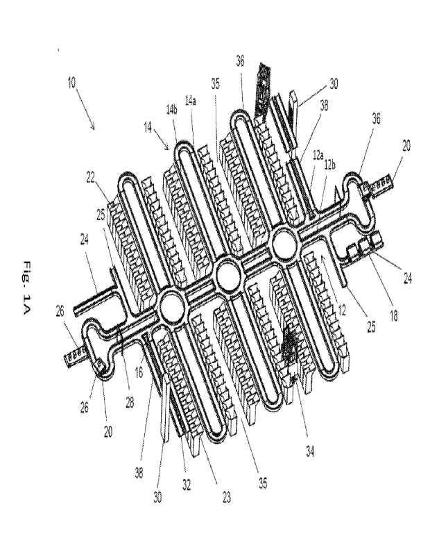
[0061] Fig. 1A schematically illustrates a level of a sorting system, in
accordance with
an embodiment of the present invention. Fig. 1B schematically illustrates a
layout of the
level shown in Fig. 1A.
[0062] Sorting system level 10 includes a path network 11 along which
transporter units
18 may travel. In the example shown, sorting system level 10 represents a
single level
of multilevel sorting system (e.g., as depicted in Fig. 2A). In the example
shown, the
paths are depicted as tracks, which may include rails, channels, or roadways
on which
transporter units 18 in the form of wheeled or otherwise bottom-supported
(e.g.,
magnetically, pneumatically, by floatation, or otherwise supported) carts or
other
vehicles may travel. In other examples, the paths may include overhead rails
or other
11
WO 2020/194287
PCT/11,2020/050216
overhead structure from which transporter units 18 may be suspended (e.g.,
mechanically or magnetically).
[0063] In the example shown, path network 11 includes a single thoroughfare
path 12
that is intersected by a plurality of distribution paths 14 at junctions 16.
In other
examples, a path network may include multiple thoroughfare paths, a central
thoroughfare region surrounded by peripheral distribution paths 14, or another
arrangement. In the example shown, thoroughfare path 12 includes two separate
one-
way tracks 12a and 12b. Sorting system level 10 is configured such that
transporter
units 18 travel in a single and opposite directions along each track 12a and
12b.
Similarly, each distribution path 14 includes two separate one-way tracks 14a
and 14b.
Arrows 19 schematically illustrate a possible direction of travel of
transporter units 18
along each track 12a, 12b, 14a, or 14b. In other examples, the directions of
some or all
of arrows 19 may be reversed. As a typical example, each track 12a, 12b, 14a,
or 14b
may represent a rail or a railway track. In other examples, track 12a, 12b,
14a, or 14b
may represent a lane of a roadway, an overhead rail, a channel, or other one-
way path.
[0064] In other examples, each path of path network 11 may be configured to
enable
two-way traffic of transporter units 18 along the path. For example, each path
may be
sufficiently wide to enable two-way traffic of (e.g., self-propelled)
transporter units 18
without collision. A controller of the sorting system, or of each transporter
unit 18, may
control motion of transporter units 18 to avoid collisions when travelling
along a two-
way path.
[0065] Each end of each thoroughfare path 12 or distribution path 14
terminates in a
connecting loop 36 or in a junction 16. Thus, a transporter unit 18 that
reaches an end of
a track 12a or 12b of thoroughfare path 12, or of a track 14a or 14b of a
distribution path
14, that terminates in a connecting loop 36 may continue to travel around
connecting
loop 36 to reverse direction and travel in the opposite direction along track
12b or 12a,
or track 14b or 14a, respectively. When a transporter unit 18 reaches a
junction 16 when
travelling along a track of a path of path network 11 (e.g., along track 12a
or 12b of
thoroughfare path 12, or along track 14a or 14b of a distribution path 14),
the
transporter unit 18 may be controlled to continue to travel along that
original track, to
reverse direction by travelling around that junction 16 to the opposite track
of the
12
WO 2020/194287
PCT/11,2020/050216
original path, or to turn to a track of an intersecting path (e.g., to a track
of distribution
path 14 or of thoroughfare path 12, respectively).
[0066] In the example shown, each junction 16 is a track having a
substantially circular
closed form that functions as a roundabout or traffic circle. Thus, a
transporter unit 18
that enters junction 16 may continue to travel about the roundabout of
junction 16 until
an intersection of junction 16 with a track of a path along which transporter
unit 18 is to
continue to travel. In other examples, a junction may be otherwise designed
(e.g., with
rounded rectangular or polygonal roundabouts, by including a turntable
mechanism, by
providing transporter units 18 with steering mechanisms capable of turning at
right or
obtuse angles, or another design or mechanism) to enable diversion or a
transporter unit
18 from one path to an intersecting path.
[0067] In the example shown, path network 11 is designed such that when a
transporter
unit 18 is travelling along a path in the direction indicated by the
corresponding arrow
19, any intersection between two intersecting paths or between a path and a
junction 16
forms an acute angle opening toward the direction of travel. In this manner, a
switching
mechanism (e.g., a rotation through an acute angle of a steering mechanism of
transporter unit 18, of a rotatable rail of the path, or of another switching
mechanism)
may divert the direction of travel from one path to the intersecting path,
e.g., without
requiring slowing of a speed of travel of transporter unit 18. In some
examples, a
switching mechanism may include an electromagnetic power switching mechanism.
[0068] In the example shown, a loading station 20 is located at a connecting
loop 36 at
each end of thoroughfare path 12. In other examples, one or more loading
stations 20
may be located elsewhere within path network 11. Each loading station 20 is
configured
to load one or more parcels 26 on a transporter unit 18. For example, a
loading station
20 may include one or more of a conveyer belt, hoist, robotic arm, crane,
chute, or other
mechanism for loading a parcel 26 onto a transporter unit 18.
[0069] In the example shown, destination stations 22 are distributed along
distribution
paths 14. In other examples, destination stations 22 may be otherwise
distributed along
path network 11 or sorting system level 10. In the example shown, each
destination
station 22 includes a collection bin and/or a sack into which a parcel 26 may
be
deposited, e.g., via a deposit chute 23. In other examples, a destination
station 22 may
13
WO 2020/194287
PCT/11,2020/050216
include a cage, a shelf, or another structure or region for holding a parcel
26. For
example, destination station 22 may include labelling that identifies
destination station
22 to a sensor of transporter unit 18, or a sensor that detects labelling on
transporter unit
18 or a parcel 26. Alternatively or in addition, a navigation system of each
transporter
unit 18, or of the sorting system, may monitor a location of each transporter
unit 18
relative to a selected destination station 22 (as well as to all other
transporter units18
that are currently located on path network 11) to which that transporter unit
18 is to
deliver parcel 26. Destination station 22, transporter unit 18, or another
component of
the sorting system may be configured to remove parcel 26 from transporter unit
18 to
destination station 22. For example, a surface of transporter unit 18 on which
parcel 26
is supported may be tilted, a pushing or grabbing mechanism may remove parcel
26
from transporter unit 18, or another mechanism, structure, or device may move
a parcel
26 from a transporter unit 18 to an appropriate destination station 22.
[0070] In the example shown, sorting system level 10 includes logistic lanes
35
between destination paths 14 to enable access by a parcel-handling vehicle 34
to access
destination stations 22. For example, parcel-handling vehicle 34 may be
operated to
remove parcels 26 from a destination station 22 for delivery to a target
destination (e.g.,
a final destination, a delivery or transport vehicle or service, or
elsewhere).
[00711 Path network 11 may include one or more parking areas 18 and one or
more
maintenance areas 25. For example, a transporter unit 18 may remain in a
parking area
18 when that transporter unit 18 is not loaded with a parcel 26, and when
there is no
need for loading a parcel 26 onto that transporter unit 18. A transporter unit
18 may be
moved to a maintenance area 25 to enable performance of maintenance on that
transporter unit 18, to enable removal of a transporter unit 18 from path
network 11, or
to enable addition of a transporter unit 18 to path network 11, without
interfering with
operation of other transporter units 18 that are traveling or otherwise
operating on path
network 11.
[0072] Reader 28 is configured to read one or more identifying labels of
parcel 26,
transporter unit 18, or both. The identifying label may include one or more
optical (e.g.,
alphanumeric characters, symbols, one- or two-dimensional barcodes, color
patterns,
emitted light pattern (e.g., by light emitting diodes), or other optical
labelling),
14
WO 2020/194287
PCT/11,2020/050216
electromagnetic (e.g., RF1D tags, electromagnetic transmitters, or other
electromagnetic
labelling), acoustic, or other readable labelling. Reader 28 may include one
or more
devices (e.g., optical scanner, RF1D reader, acoustic transponder, or other
device) for
reading or interrogating the labelling. The labelling may indicate a
destination station 22
to which parcel 26 is to be delivered. In the example shown, reader 28 is
mounted on a
bridge above a path (e.g., thoroughfare path 12) of path network 11 and is
configured to
read labelling immediately after transporter unit 18 departs from loading
statin 20. In
other examples, sensors of reader 28, or of additional readers, may be placed
alongside
or under a path of path network 11, and elsewhere along path network 11.
[00731 Controller 13 is configured to control operation of components of the
sorting
system, including sorting system level 10. For example, controller 13 may
include one
or more computers or other processing units. The processors of controller 13
may be
located at one or more fixed locations within or remote to the sorting system.
Alternatively or in addition, some or all of the processors of controller 13
may be
located on transporter units 18.
[0074] Controller 13 may be configured to calculate a most direct route along
path
network 11 from a loading station 20, at which a parcel 26 is placed on a
transporter
unit 18, to a destination station 22 for delivery of that parcel 26. In some
cases,
calculation of the most direct route may include minimizing travel time, e.g.,
utilizing
the current or calculated future locations of other transporter units 18
within path
network 11, from loading station 20 to destination station 22.
[00751 Path network 11 may include an arrangement of sensors (e.g., optical,
acoustic,
electromagnetic, electromechanical, or otherwise) that are configured to
continuously
monitor the position of each transporter unit 18. For example, such sensors
may be
arranged along paths of path network 11 at regular or irregular intervals.
Alternatively
or in addition, one or more cameras or other imaging devices may be configured
to
acquire images of all transporter units 18 on path network 11. Acquired images
may be
analyzed to determine the location of each transporter unit 18 on path network
11.
Alternatively or in addition, each transporter unit 18 may be provided with
one or more
navigation sensors or devices to determine its position relative to path
network 11 (or to
a local or global coordinate system relative to which the positions of paths
of path
WO 2020/194287
PCT/11,2020/050216
network 11 are known). Controller 13 may be configured to receive signals from
the
sensors or devices and determine the positions of all transporter units 18
that are located
on path network 11.
[0076] In the example shown, sorting system level 10 is one level of a
multilevel
sorting system. A transporter unit 18 that is to be raised or lowered to
another level of
the sorting system may be moved to elevator approach path 38 and onto lift 32
of
elevator 30.
[0077] Fig. 2A schematically illustrates a hi-level sorting system, in
accordance with an
embodiment of the invention. Fig. 2B schematically illustrates a vertical
junction of the
sorting system shown in Fig. 2A. Fig. 2C is a schematic side view of the
sorting system
shown in Fig. 2A.
[0078] Bi-level path network 42 of sorting system 40 includes lower level 10a
(corresponding to sorting system level 10 of Figs. 1A-1B) and upper level 10b.
In other
examples, a sorting system may include three or more levels.
[00791 In the example shown, the layout of upper level 10b is identical to
that of lower
level 10a, except that all loading stations 20, parking areas 24, and
maintenance areas
25 are located on lower level 10a. Destination stations 22 are located along
both lower
level 10a and upper level 106. In other examples, some or all loading stations
20,
parking areas 24, and maintenance areas 25 may be located on upper levels, and
paths
of upper levels may be laid out differently than at lower levels. In the
example shown,
logistic lanes 35 are located below lower level 10a. In other examples,
logistic lanes 35
may be located level with or higher than lower level 10a.
[0080] In some cases, destination stations 22 on upper level 10b may be
identical to
destination stations 22 on lower level 10a (e.g., a single tall bin). In this
case, the hi-
level network of paths may reduce traffic congestion along the distribution
paths 14 on
the different levels. In other cases, destination stations 22 on upper level
10b may be
different from those on lower level 10a, allowing for increasing the number of
destination stations 22 in sorting system 40.
[0081] In the example shown, a vertical junction between upper level 10b and
lower
level 10a includes elevator 30. In other example, a vertical junction may
include a ramp
16
WO 2020/194287
PCT/11,2020/050216
(e.g., an upwardly or downwardly sloping path or track, or another arrangement
for
enabling a transporter unit 18 to travel between levels of sorting system 40.
[0082] In the example shown, elevator 30 is configured to raise lift 32 from
elevator
approach path 38 of lower level 10a to elevator approach path 44 of upper
level 10b, or
vice versa. For example, in Fig. 2A, both lifts 32 are shown at the elevation
of elevator
approach path 38 of lower level 10a. In Fig. 2B, lift 32 is shown raised to an
elevation
between that of lower level 10a and that of elevator approach path 44 of upper
level
10b.
[0083] Fig. 3A schematically illustrates a sorting system in which destination
stations
are located at the periphery. Fig. 3B schematically illustrates a layout of
the system
shown in Fig. 3A.
[0084] In the example shown, sorting system 50 is located within enclosure 52
(e.g., a
warehouse or other building) and is accessible via openings 54. In sorting
system 50,
distribution paths 14 along which destination stations 22 are arranged are
located at the
periphery of central path region 56. Similarly, loading stations 20 are
located at
connecting loops 36 at the distal ends of distribution paths 14, near openings
54. In
other examples, loading stations 20 may be otherwise located.
[0085] In the example shown, the distal end of each distribution path 14 is
located at an
opening 54. Such an arrangement may enable access by a delivery vehicle (e.g.,
truck,
van, cargo cart, forklift, crane, cherry picker, cargo boat, or other
transport vehicle) to
access the loading station 20 or the destination stations 22 at that opening
54.
[0086] In the example shown, central path region 56 is arranged in the form of
a grid of
thoroughfare paths 12 intersecting substantially at right angles. The
intersecting
thoroughfare paths 12 meet at junctions 16. In the example shown, junctions 16
are
approximately rectangular, deviating outward from thoroughfare paths 12 that
are
oriented in one direction (vertically in Fig. 3B). In other examples,
junctions 16 may be
otherwise shaped (e.g., circular as in Fig. 1A, square, oval, polygonal, or
otherwise).
[0087] The ends of each thoroughfare path 12 terminate in two distribution
paths 14 in
the forms of extensions of thoroughfare path 12 at the periphery of central
path region
56. Other arrangements of paths are possible (e.g., diagonal intersections
between some
or all of the paths, curved or bent paths, or other arrangements).
17
WO 2020/194287
PCT/11,2020/050216
[0088] In the example shown, the lateral separation between adjacent parallel
thoroughfare paths 12 that extend in one dimension (vertically in Fig. 3B) is
greater
than between adjacent thoroughfare paths 12 that extend in the other dimension
(horizontally in Fig. 3B). In other examples, the separations between adjacent
thoroughfare paths 12 may be substantially equal in both dimensions.
[0089] The grid arrangement of thoroughfare paths 12 in sorting system 50 may
enable
increased flexibility in selection of a route over another arrangement of the
paths, e.g.,
as in sorting system level 10. The grid arrangement in sorting system 50 may
also be
used to sort parcels from one loading station 20 (e.g., at one end of
enclosure 52) to
other loading stations 20 (e.g., at other ends of enclosure 52, and possibly
functioning as
destination stations). For example, such sorting may facilitate further
transport of
parcels either within sorting system 50, or to another sorting system (e.g.,
via an
opening 54 of enclosure 52).
[0090] Fig. 4 schematically illustrates a variant layout of the system shown
in Fig. 3B.
[0091] In central path region 62 of sorting system 60, junctions 16 are shown
as aligned
with all thoroughfare paths 12. Thus, a transporter unit 18 that traverses a
junction 16
along one thoroughfare path 12 without turning to an intersecting thoroughfare
path 12
may continue without turning.
[0092] Fig. 5 schematically illustrates a layout of a variant of the system
shown in Fig.
1B, the layout including a peripheral path.
[0093] In path network 70, peripheral path 72 extends about the periphery of,
and
surrounds interior paths of, (e.g., one or more thoroughfare paths 12 and a
plurality of
distribution paths 14) path network 70. In the example shown, loading stations
20 are
arranged along peripheral path 72. A transporter unit 18 may travel along
peripheral
path 72 to a peripheral junction 74 with thoroughfare path 12 or with a
distribution path
14. In the example shown, the interior of path network 70 is similar to that
of path
network 11 (Fig. 1B). In other examples, the interior of path network 70 may
be similar
to the path network of sorting system 50 (Fig. 3B), sorting system 60 (Fig.
4), or
another path network. Peripheral path 70 may expedite delivery by enabling a
transporter unit 18 to bypass large regions of path network 70, without
traversing many
or all thoroughfare paths 12 and junctions 16.
18
WO 2020/194287
PCT/11,2020/050216
[0094] Fig. 6 is a flowchart depicting a method for controlling travel of a
transporter
unit of a sorting system in accordance with an embodiment of the invention.
[0095] It should be understood with respect to any flowchart referenced herein
that the
division of the illustrated method into discrete operations represented by
blocks of the
flowchart has been selected for convenience and clarity only. Alternative
division of the
illustrated method into discrete operations is possible with equivalent
results. Such
alternative division of the illustrated method into discrete operations should
be
understood as representing other embodiments of the illustrated method.
[0096] Similarly, it should be understood that, unless indicated otherwise,
the illustrated
order of execution of the operations represented by Mocks of any flowchart
referenced
herein has been selected for convenience and clarity only. Operations of the
illustrated
method may be executed in an alternative order, or concurrently, with
equivalent
results. Such reordering of operations of the illustrated method should be
understood as
representing other embodiments of the illustrated method.
[0097] Control method 100 may be executed by controller 13 of a sorting system
as
describe herein. Control method 100 may be executed, e.g., when a parcel 26 is
loaded
onto a transporter unit 18 at a loading station 20, or is removed from
transporter unit 18
at a destination station 22. In some cases, control method 100 may be executed
during
travel of transporter unit 18 along a path network of the sorting system. For
example,
control method 100 may be executed periodically to evaluate current traffic
conditions
along some or all paths, or may be executed in response to a detected change
in traffic
conditions.
[0098] A current location of transporter unit 18 may be determined (block
110). For
example, controller 13 may receive signals that are indicative of the current
location of
transporter unit 18 from one or more sensors or navigation devices. The
current location
may be a loading station 20, the location of a reader 28, a destination
station 22, or
another location.
[0099] A destination for transporter unit 18 may be determined (block 120).
For
example, labelling on a loaded parcel 26 may indicate a final destination for
parcel 26.
Controller 13 may determine a destination station 22 for parcels 26 with that
final
destination. As another example, after unloading parcel 26 at destination
station 22,
19
WO 2020/194287
PCT/11,2020/050216
controller 13 may determine a loading station 20 at which transporter unit 18
is to be
loaded with another parcel 26, a parking area 24 at which transporter unit 18
is to be
parked, or a maintenance area 25 at which maintenance is to be performed on
transporter unit 18. When there are more than one loading station 26, parking
area 24, or
maintenance area 25, controller 13 may select one of these as a destination
for a
transporter unit 18.
[00100]
Controller 13 may calculate a most direct route to
the determined
destination (block 130). For example, the most direct mute may include a
shortest travel
distance to the destination, a route with the shortest travel time to the
destination (e.g.,
taking into account current or projected traffic conditions, projected travel
speed on
each path, or other conditions), a route requiring the lowest expenditure of
energy, or
otherwise. The calculated route includes instructions regarding a continued
direction of
travel at each junction 16 that is encountered by transporter unit 18.
[00101]
Controller 13 may then cause transporter unit 18 to
be moved (e.g., either
externally propelled or self-propelled) along the calculated most direct route
to the
destination. If the destination is a destination station 22, parcel 26 may be
removed from
transporter unit 18.
[00102]
Different embodiments are disclosed herein.
Features of certain
embodiments may be combined with features of other embodiments such that
certain
embodiments may be combinations of features of multiple embodiments. The
foregoing
description of the embodiments of the invention has been presented for the
purposes of
illustration and description. It is not intended to be exhaustive or to limit
the invention
to the precise form disclosed. It should be appreciated by persons skilled in
the art that
many modifications, variations, substitutions, changes, and equivalents are
possible in
light of the above teaching. It is, therefore, to be understood that the
appended claims
are intended to cover all such modifications and changes as fall within the
true spirit of
the invention.
[00103]
While certain features of the invention have been
illustrated and
described herein, many modifications, substitutions, changes, and equivalents
will now
occur to those of ordinary skill in the art. It is, therefore, to be
understood that the
WO 2020/194287
PCT/1L2020/050216
appended claims are intended to cover all such modifications and changes as
fall within
the true spirit of the invention.
21