Note: Descriptions are shown in the official language in which they were submitted.
CA 03129400 2021-08-06
WO 2020/163615
PCT/US2020/017039
MOTORIZED LATCH RETRACTION WITH RETURN BOOST
TECHNICAL FIELD
[0001] The present disclosure generally relates to access control devices,
and more particularly
but not exclusively relates to exit devices.
BACKGROUND
[0002] Exit devices are commonly installed to doors to facilitate egress
from a room. Certain
exit devices include electronic actuators operable to actuate the exit device
to provide for push-
pull operation of the door on which the exit device is installed. However, it
has been found that
while certain existing electronic actuators are capable of transitioning the
exit device to the
actuated state thereof, there are circumstances in which the actuator prevents
return of the exit
device to the deactuated state upon removal of electrical power from the
actuator. For these
reasons among others, there remains a need for further improvements in this
technological field.
SUMMARY
[0003] An exemplary electronic actuator assembly is configured for use with
a pushbar assembly
having a drive assembly operable to retract a latchbolt, and includes an input
shaft, a motor, and
a boost spring. The motor has a retracting state in which the motor drives the
input shaft from a
proximal position to a distal position, a holding state in which the motor
exerts a holding force to
retain the input shaft in the distal position, and a releasing state in which
the motor exerts a
residual force that resists movement of the input shaft. The boost spring
exerts a boost force
urging the input shaft in the proximal direction to at least partially
counteract the residual force.
Further embodiments, forms, features, and aspects of the present application
shall become
apparent from the description and figures provided herewith.
1
CA 03129400 2021-08-06
WO 2020/163615
PCT/US2020/017039
BRIEF DESCRIPTION OF THE FIGURES
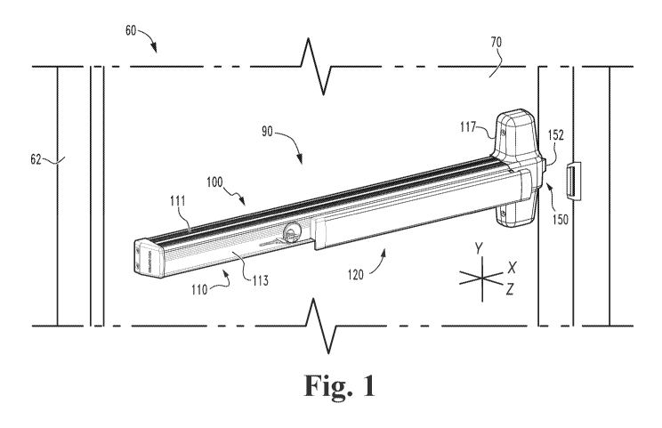
[0004] FIG. 1 is a perspective illustration of a closure assembly including
an exit device
according to certain embodiments.
[0005] FIG. 2 is a cross-sectional illustration of the exit device
illustrated in FIG. 1.
[0006] FIG. 3 is a perspective illustration of an electronic actuator
assembly according to certain
embodiments.
[0007] FIG. 4 is a first cross-sectional illustration of the electronic
actuator assembly illustrated
in FIG. 3.
[0008] FIG. 5 is a second cross-sectional illustration of the electronic
actuator assembly
illustrated in FIG. 3.
[0009] FIG. 6 is a schematic block diagram of a control assembly according
to certain
embodiments.
[0010] FIG. 7 is a schematic block diagram of a computing device.
DETAILED DESCRIPTION OF ILLUSTRATIVE EMBODIMENTS
[0011] Although the concepts of the present disclosure are susceptible to
various modifications
and alternative forms, specific embodiments have been shown by way of example
in the
drawings and will be described herein in detail. It should be understood,
however, that there is
no intent to limit the concepts of the present disclosure to the particular
forms disclosed, but on
the contrary, the intention is to cover all modifications, equivalents, and
alternatives consistent
with the present disclosure and the appended claims.
[0012] References in the specification to "one embodiment," "an
embodiment," "an illustrative
embodiment," etc., indicate that the embodiment described may include a
particular feature,
structure, or characteristic, but every embodiment may or may not necessarily
include that
particular feature, structure, or characteristic. Moreover, such phrases are
not necessarily
referring to the same embodiment. It should further be appreciated that
although reference to a
"preferred" component or feature may indicate the desirability of a particular
component or
feature with respect to an embodiment, the disclosure is not so limiting with
respect to other
embodiments, which may omit such a component or feature. Further, when a
particular feature,
structure, or characteristic is described in connection with an embodiment, it
is submitted that it
2
CA 03129400 2021-08-06
WO 2020/163615
PCT/US2020/017039
is within the knowledge of one skilled in the art to implement such feature,
structure, or
characteristic in connection with other embodiments whether or not explicitly
described.
[0013] As used herein, the terms "longitudinal," "lateral," and
"transverse" are used to denote
motion or spacing along three mutually perpendicular axes, wherein each of the
axes defines two
opposite directions. The directions defined by each axis may be referred to as
positive and
negative directions, wherein the arrow of the axis indicates the positive
direction. In the
coordinate system illustrated in FIG. 1, the X-axis defines first and second
longitudinal
directions, the Y-axis defines first and second lateral directions, and the Z-
axis defines first and
second transverse directions. These terms are used for ease and convenience of
description, and
are without regard to the orientation of the system with respect to the
environment. For example,
descriptions that reference a longitudinal direction may be equally applicable
to a vertical
direction, a horizontal direction, or an off-axis orientation with respect to
the environment.
[0014] Furthermore, motion or spacing along a direction defined by one of
the axes need not
preclude motion or spacing along a direction defined by another of the axes.
For example,
elements which are described as being "laterally offset" from one another may
also be offset in
the longitudinal and/or transverse directions, or may be aligned in the
longitudinal and/or
transverse directions. The terms are therefore not to be construed as limiting
the scope of the
subject matter described herein.
[0015] Additionally, it should be appreciated that items included in a list
in the form of "at least
one of A, B, and C" can mean (A); (B); (C); (A and B); (B and C); (A and C);
or (A, B, and C).
Similarly, items listed in the form of "at least one of A, B, or C" can mean
(A); (B); (C); (A and
B); (B and C); (A and C); or (A, B, and C). Further, with respect to the
claims, the use of words
and phrases such as "a," "an," "at least one," and/or "at least one portion"
should not be
interpreted so as to be limiting to only one such element unless specifically
stated to the contrary,
and the use of phrases such as "at least a portion" and/or "a portion" should
be interpreted as
encompassing both embodiments including only a portion of such element and
embodiments
including the entirety of such element unless specifically stated to the
contrary.
[0016] In the drawings, some structural or method features may be shown in
certain specific
arrangements and/or orderings. However, it should be appreciated that such
specific
arrangements and/or orderings may not necessarily be required. Rather, in some
embodiments,
such features may be arranged in a different manner and/or order than shown in
the illustrative
3
CA 03129400 2021-08-06
WO 2020/163615
PCT/US2020/017039
figures unless indicated to the contrary. Additionally, the inclusion of a
structural or method
feature in a particular figure is not meant to imply that such feature is
required in all
embodiments and, in some embodiments, may not be included or may be combined
with other
features.
[0017] With reference to FIG. 1, illustrated therein is a closure assembly
60 including a swinging
door 70 and an exit device 90 mounted to the door 70. The door 70 is mounted
to a doorframe
62 for swinging movement between an open position and a closed position, and
the exit device
90 is configured to selectively retain the door 70 in the closed position. In
certain embodiments,
the closure assembly 60 may be considered to further include the doorframe 62.
The closure
assembly 60 has a plurality of states or conditions, including a secured
condition, an unsecured
condition, and an open condition. In the secured condition, the door 70 is in
its closed position,
the exit device 90 is in a deactuated state, and the exit device 90 engages
the doorframe and
retains the door 70 in its closed position. Actuation of the exit device 90
causes the closure
assembly 60 to transition to the unsecured condition, in which the door 70 is
capable of being
moved from its closed position to its open position under push/pull operation.
Such movement
of the door 70 to its open position causes the closure assembly 60 to
transition to the open
condition.
[0018] With additional reference to FIG. 2, the exit device 90 generally
includes a pushbar
assembly 100, which includes a mounting assembly 110 configured for mounting
to the door 70,
a drive assembly 120 mounted to the mounting assembly 110 for movement between
an actuated
state and a deactuated state, a latch control assembly 140 operably connected
with the drive
assembly 120 via a lost motion connection 108, and a latchbolt mechanism 150
operably coupled
with the latch control assembly 140. The exit device 90 further includes an
electronic actuator
assembly 130 that is mounted in the pushbar assembly 100 and is operable to
transition the drive
assembly 120 between the actuated state and the deactuated state.
[0019] As described herein, the drive assembly 120 is biased toward the
deactuated state, and is
operable to be driven to the actuated state when manually actuated by a user
or when electrically
actuated by the electronic actuator assembly 130. The latch control assembly
140 also has an
actuated state and a deactuated state, and is operably connected with the
drive assembly 120 such
that actuation of the drive assembly 120 causes a corresponding actuation of
the latch control
assembly 140.
4
CA 03129400 2021-08-06
WO 2020/163615
PCT/US2020/017039
[0020] The mounting assembly 110 generally includes an elongated channel
member 111, a base
plate 112 mounted in the channel member 111, and a pair of bell crank mounting
brackets 114
coupled to the base plate 112. The channel member 111 extends along the
longitudinal (X) axis
102, has a width in the lateral (Y) directions, and has a depth in the
transverse (Z) directions.
Each of the mounting brackets 114 includes a pair of laterally-spaced walls
that extend away
from the base plate 112 in the forward (Z+) direction. The illustrated
mounting assembly 110
also includes a faceplate 113 that encloses a distal end portion of the
channel member 111, a
header plate 116 positioned adjacent a proximal end of the channel member 111,
and a header
casing 117 mounted to the header plate 116.
[0021] The drive assembly 120 includes a drive rod 122 extending along the
longitudinal axis
102, a pushbar 124 having a pair of pushbar brackets 125 mounted to the rear
side thereof, and a
pair of bell cranks 126 operably connecting the drive rod 122 with the pushbar
124. As
described herein, the drive rod 122 is mounted for movement in the
longitudinal (X) directions,
the pushbar 124 is mounted for movement in the transverse (Z) directions, and
the bell cranks
126 couple the drive rod 122 and the pushbar 124 for joint movement during
actuation and
deactuation of the drive assembly 120. Each bell crank 126 is pivotably
mounted to a
corresponding one of the bell crank mounting brackets 114. Each bell crank 126
includes a first
arm pivotably connected to the drive rod 122, and a second arm pivotably
connected to a
corresponding one of the pushbar brackets 125. The pivotal connections may,
for example, be
provided by pivot pins 121. The drive assembly 120 further includes a return
spring 127 that is
engaged with the mounting assembly 110 and which biases the drive assembly 120
toward its
deactuated state.
[0022] Each of the drive rod 122 and the pushbar 124 has an actuated
position in the actuated
state of the drive assembly 120, and a deactuated position in the deactuated
state of the drive
assembly 120. During actuation and deactuation of the drive assembly 120, the
drive rod 122
moves in the longitudinal (X) directions between a proximal deactuated
position and a distal
actuated position, and the pushbar 124 moves in the transverse (Z) directions
between a
projected or forward deactuated position and a depressed or rearward actuated
position. Thus,
during actuation of the drive assembly 120, the drive rod 122 moves in the
distal (X-) direction,
and the pushbar 124 moves in the rearward (Z-) direction. Conversely, during
deactuation of the
drive assembly 120, the drive rod 122 moves in the proximal (X+) direction,
and the pushbar 124
CA 03129400 2021-08-06
WO 2020/163615
PCT/US2020/017039
moves in the forward (Z+) direction. The bell cranks 126 translate
longitudinal movement of the
drive rod 122 to transverse movement of the pushbar 124, and translate
transverse movement of
the pushbar 124 to longitudinal movement of the drive rod 122.
[0023] With the drive assembly 120 in its deactuated state, a user may
depress the pushbar 124
to transition the drive assembly 120 to its actuated state. As the pushbar 124
is driven toward its
depressed position, the bell cranks 126 translate the rearward movement of the
pushbar 124 to
distal movement of the drive rod 122, thereby compressing the return spring
127. When the
actuating force is subsequently removed from the pushbar 124, the spring 127
returns the drive
rod 122 to its proximal position, and the bell cranks 126 translate the
proximal movement of the
drive rod 122 to forward movement of the pushbar 124, thereby returning the
drive assembly 120
to its deactuated state.
[0024] The electronic actuator assembly 130 includes a link 132 operably
coupled with the drive
rod 122, an input shaft 133 coupled to the link 132 via a lost motion
connection 134, and a motor
135 operable to drive the input shaft 133 and the link 132 from a proximal
extended position to a
distal retracted position. The electronic actuator 130 generally has three
states: a retracting state,
a holding state, and a releasing state. In the retracting state, the motor 135
exerts a sufficient
retracting force on the input shaft 133 to overcome the biasing force of the
spring 127 such that
the drive rod 122 moves to its retracted position, thereby actuating the drive
assembly 120. In
the holding state, the motor 135 exerts a sufficient holding force on the
input shaft 133 to retain
the drive rod 122 in its retracted position against the biasing force of the
return spring 127,
thereby holding or retaining the drive assembly 120 in its actuated state.
[0025] With the motor 135 in the releasing state, the motor 135 exerts a
residual holding force
resisting movement of the plunger 132 in the proximal direction. The biasing
force of the return
spring 127 partially counteracts the residual force exerted by the motor 135,
but is insufficient to
overcome the residual return to the extended positions thereof under the force
of the return
spring 127. As described herein, the electronic actuator 130 itself provides a
supplemental boost
force that aids in overcoming the residual force to return the drive assembly
120 to its deactuated
state when the actuator 130 is in the releasing state.
[0026] The latch control assembly 140 includes a control link 142 and a
yoke 144 that is coupled
to a retractor 154 of the latchbolt mechanism 150 such that movement of the
control link 142 in
the distal direction (to the left in FIG. 3) actuates the latchbolt mechanism
150 and retracts the
6
CA 03129400 2021-08-06
WO 2020/163615
PCT/US2020/017039
latchbolt 152. The control link 142 is coupled with the drive rod 122 via the
lost motion
connection 108 such that retraction of the drive rod 122 (i.e., movement of
the drive rod from its
proximal or extended position to its distal or retracted position) causes a
corresponding retraction
of the control link 142, thereby retracting the latchbolt 152. Thus,
retraction of the drive rod 122
by either the pushbar 124 or the electronic actuator 130 serves to retract the
latchbolt 152.
[0027] Should the drive assembly 120 remain in its actuated state, the
drive rod 122 will remain
in its retracted position, and the latchbolt 152 will accordingly remain
retracted. Thus, when the
electronic actuator 130 is in the holding state, the exit device 90 remains
dogged, and the door 70
can be opened from either the secured side or the unsecured side by applying
the appropriate one
of a pushing force or a pulling force. When power to the actuator 130 is
subsequently removed,
the drive assembly 120 and the latchbolt mechanism 150 return to the extended
or deactuated
states thereof under the internal biasing forces of the pushbar assembly 100,
including those
biasing forces provided by the spring 127 and the electronic actuator assembly
130.
[0028] With additional reference to FIGS. 3-5, illustrated therein is an
electronic actuator
assembly 200 according to certain embodiments, which may be utilized as the
electronic actuator
assembly 130 of the exit device 90. The electronic actuator assembly 200
generally includes a
housing 210, a link 220 mounted for sliding reciprocal movement within the
housing 210, an
input shaft 230 connected to the link 220 via a lost motion connection 240, a
motor 250 operable
to drive the input shaft 230 in the proximal and distal directions, and a
control assembly 260
operable to control operation of the motor 250. As described herein, the
electronic actuator
assembly 200 further includes a boost assembly 270 acting on the input shaft
230 upstream of the
lost motion connection 240 such that the boost assembly 270 at all times
biases the input shaft
230 toward its deactuated or proximal position.
[0029] The housing 210 is affixed to the body portion 252 of the motor 250,
and the actuator
assembly 200 is secured to the mounting assembly 110 such that the housing 210
has a fixed
position within the pushbar assembly 100. The housing 210 has a pair of
sidewalls 212, each of
which defines a corresponding and respective one of a pair of longitudinal
channels 213. A
coupling pin 203 passes through the input shaft 230 and is received in the
channels 213 such that
the shaft 230 is slidably connected to the housing 210, thereby preventing
rotation of the shaft
230 relative to the housing 210.
7
CA 03129400 2021-08-06
WO 2020/163615
PCT/US2020/017039
[0030] The link 220 is slidably mounted in the housing 210 for reciprocal
movement in the
proximal and distal directions. The link 220 is configured for connection to
the drive assembly
120 such that movement of the link 220 from a proximal extended position to a
distal retracted
position causes retraction of the latchbolt 152 in the manner described above.
The link 220
includes a body portion 222 defining a pair of longitudinal slots 223 and a
shoulder 224, a distal
wall 226 positioned distally of the body portion 222, and a proximal arm 228
that extends
proximally from the body portion 222 and terminates in a hook 229 by which the
link 220 is
coupled to the drive rod 122.
[0031] The input shaft 230 is operably connected with the motor 250 such
that the motor 250 is
operable to drive the input shaft 230 in the proximal and distal directions.
The input shaft 230
has a proximal end portion 232 defining a through-hole 233 and a distal end
portion 234 engaged
with the motor 250. In the illustrated form, at least the distal end portion
234 is threaded, and
rotation of the shaft 230 relative to the housing 210 and the motor body 252
is prevented at least
in part by the coupling pin 203. In certain forms, the input shaft 230 may
include a splined
section that engages a corresponding splined section in the motor housing 252
to further aid in
preventing rotation of the shaft 230. As described herein, the shaft 230 is
threadedly engaged
with a rotor 254 of the motor 250 such that rotation of the rotor 254 in
opposite rotational
directions drives the shaft 230 to reciprocate in opposite longitudinal
directions.
[0032] The lost motion connection 240 is defined in part by the coupling
pin 203, and includes
an overtravel spring 242 engaged between the link 220 and the input shaft 230.
In the illustrated
form, the overtravel spring 242 has a distal end 243 that is seated in a
collar 246 and is engaged
with the distal wall 226, and a proximal end 244 that is engaged with the
coupling pin 203 such
that the spring 240 is operable to transmit forces between the link 220 and
the input shaft 230.
As noted above, the coupling pin 203 slidably couples the link 220 and the
input shaft 230 to the
housing 210. Due to the provision of the longitudinal slots 223, the coupling
pin 203 also
facilitates lost motion between the link 220 and the input shaft 230, thereby
permitting
alterations in the relative position of the link 220 and the input shaft 230.
[0033] The motor 250 includes a body portion 252 and a rotor 254 that is
rotatable relative to the
body portion 252. The rotor 254 is threadedly engaged with the threaded distal
end portion 234,
and the motor 250 is configured to rotate the rotor 254 based upon signals
received from the
control assembly 260. As noted above, rotation of the shaft 230 relative to
the body portion 252
8
CA 03129400 2021-08-06
WO 2020/163615
PCT/US2020/017039
is prevented, for example by engagement between the coupling pin 203 and the
housing 210.
Thus, rotation of the rotor 254 in a first rotational direction causes the
shaft 230 to move in the
proximal extending direction, and rotation of the rotor in an opposite second
rotational direction
causes the shaft 230 to move in the distal retracting direction. In certain
embodiments, the motor
250 may be a rotary motor, such as a stepper motor. In other embodiments, the
motor 250 may
be provided in the form of a solenoid that does not include a rotor 254, and
the input shaft 230
may be provided as the plunger of the solenoid.
[0034] With additional reference to FIG. 5, the control assembly 260 is in
communication with
the motor 250, and includes a controller 262 configured to control operation
of the motor 250.
The controller 262 is connected to a power supply 264, and is configured to
operate the motor
250 using power from the power supply 264. More particularly, the controller
262 is configured
to power the motor 250 to cause the actuator assembly 200 to operate in the
retracting state, the
holding state, and the releasing state. As will be appreciated, operating the
actuator assembly
200 in the retracting, holding, and releasing states causes retraction,
holding, and releasing of the
latchbolt 152 in the manner described above. The controller 262 may further be
in
communication with an external device 290 such as an access control system 292
and/or a
credential reader 294, and may operate the motor 250 based upon commands
received from the
external device 290.
[0035] In embodiments in which the motor 250 is provided in the form of a
stepper motor, the
controller 262 may provide the motor 250 with a series of electrical pulses to
operate the actuator
assembly 200 in the retracting state, may provide the motor 250 with a
sustained pulse to operate
the actuator assembly 200 in the holding state, and may cut power to the motor
250 to operate
the actuator assembly 200 in the release state. In embodiments in which the
motor 250 is
provided in the form of a standard rotary motor or a solenoid, the controller
262 may provide the
motor 250 with a relatively high in-rush current to operate the actuator
assembly 200 in the
retracting state, may provide the motor 250 with a relatively low operating
current to operate the
actuator assembly 200 in the holding state, and may cut power to the motor 250
to operate the
actuator assembly 200 in the releasing state.
[0036] The boost assembly 270 is mounted to the housing 210 and is engaged
with the input
shaft 230 such that the boost assembly 270 exerts a proximal boost force
urging the input shaft
230 toward its proximal or extended position. In the illustrated form, the
boost assembly 270
9
CA 03129400 2021-08-06
WO 2020/163615
PCT/US2020/017039
includes a pair of boost springs 272, each of which is seated in a
corresponding and respective
one of the channels 213. The boost assembly 270 further includes a pair of
couplers 274 that
couple first ends of the boost springs 272 with the coupling pin 203. The
opposite second ends
of the boost springs 272 are engaged with the ends of the channels 213 such
that the boost
springs 272 are captured between the housing 210 and the coupling pin 203.
[0037] During electronic operation of the exit device 90, the pushbar
assembly 100 may begin in
its deactuated state. In response to an actuating input (e.g., presentation of
an authorized
credential or receipt of an unlocking command from the access control system
292), the control
assembly 260 operates the motor 250 in the retracting state to rotate the
rotor 254 in an
unlocking direction. As a result, the input shaft 230 moves from its extended
position to its
overtravel position, thereby compressing the springs 272 of the boost assembly
270 and storing
mechanical energy therein. Movement of the shaft 230 from its proximal
extended position to its
intermediate retracted position causes a corresponding movement of the link
220 from its
proximal extended position to its distal retracted position, thereby
retracting the drive rod 122
and actuating the drive assembly 120 in the manner described above.
[0038] As the input shaft 230 moves from its intermediate retracted
position to its distal
overtravel position, the link 220 remains in its distal retracted position,
thereby causing the
overtravel spring 260 to compress. As will be appreciated, this compression
stores mechanical
energy in the overtravel spring 260, thereby increasing the biasing force
exerted by the
overtravel spring 260. As such, the biasing force exerted by the overtravel
spring 260 depends in
part upon the relative position of the link 220 and the input shaft 230. By
contrast, the boost
force provided by the boost assembly 270 depends solely upon the position of
the shaft 230
relative to the housing 210, and is therefore independent of the relative
position of the link 220
and the input shaft 230, as well as of the state of the drive assembly 120.
[0039] When the input shaft 230 reaches the distal overtravel position, the
control assembly 260
may operate the motor 250 in the holding state for a period of time. When
operating in the
holding state, the motor 250 exerts a holding force on the input shaft 230
that retains the input
shaft 230 in the distal overtravel position against the combined biasing force
of the return spring
127 and the boost assembly 270.
[0040] Following the holding operation, the control assembly 260 may cause
the motor 250 to
operate in a releasing state, for example by cutting power to the motor 250.
Those skilled in the
CA 03129400 2021-08-06
WO 2020/163615
PCT/US2020/017039
art will readily appreciate that in such instances, the motor 250 may
nonetheless exert a residual
holding force resisting movement of the input shaft 230, thereby resisting
deactuation of the
drive assembly 120. While the biasing force provided by the return spring 127
is greatest when
the drive assembly 120 is in the actuated state, in certain circumstances,
this biasing force may
be insufficient to overcome the residual force of the motor 250 in the
releasing state. In such
circumstances, the pushbar assembly 100 may fail to return to the deactuated
state, thereby
potentially permitting entry to unauthorized individuals.
[0041] In circumstances such as those described above, the pushbar assembly
100 of the current
exit device 90 will nonetheless be able to return to the deactuated state
despite the failure of the
return spring 127 to overcome the residual holding force of the motor 250. As
noted above, the
total force urging the input shaft 230 in the proximal deactuating direction
includes not only the
biasing force exerted by the return spring 127, but also the boost force
exerted by the boost
assembly 270. The boost force provided by the boost assembly 270 supplements
the biasing
force of the return spring 127 such that the combined force, which includes
both the biasing
force and the boost force, is sufficient to overcome the residual force of the
motor 250 to return
the input shaft 230 to its proximal or extended position.
[0042] During manual actuation of the pushbar assembly 100, the user
depresses the pushbar 124
to retract the drive rod 122 in the manner described above. As will be
appreciated, such distal
movement of the drive rod 122 may cause a corresponding distal movement of the
link 220. Due
to the lost motion connection 240, however, this distal movement of the link
220 is not
transmitted to the input shaft 230. Thus, during manual actuation of the
pushbar assembly 100,
the user need not overcome the residual force exerted by the motor 250 or the
boost force exerted
by the boost assembly 270. As a result, the force required to manually actuate
the pushbar
assembly 100 is unchanged.
[0043] Certain industry standards require that the actuating force not
exceed a threshold value,
and existing pushbar assemblies typically have an actuating force requirement
approaching that
threshold value. For example, where industry standards require that the
actuating force not
exceed five pounds, the actuating force for the pushbar assembly 100 may be
about five pounds.
Thus, if the electronic actuating assembly 200 were to increase the actuating
force for the
pushbar assembly 100, the actuating assembly 200 would not be permitted to be
used with the
pushbar assembly 100. However, due to the fact that the actuating assembly 200
does not
11
CA 03129400 2021-08-06
WO 2020/163615
PCT/US2020/017039
appreciably increase the actuating force for the pushbar assembly 100, the
actuating assembly
200 is capable of being used in combination with existing pushbar assemblies
without requiring
modification of the pushbar assembly 100.
[0044] In certain forms, the electronic actuating assembly 200 may be
provided as a modular
retrofit for an existing pushbar assembly 100. In particular, the electronic
actuating assembly
200 may be utilized as a retrofit for existing pushbar assemblies 100 in which
the biasing force
urging the drive assembly 120 to its deactuated state is insufficient to
overcome the residual
force resisting movement of the input shaft 230 when the motor 250 is
operating in the release
state. In such forms, the boost force provided by the boost assembly 270
supplements the
biasing force acting on the drive assembly 120, and the combined force is
sufficient to drive the
input shaft 230 to its proximal extended position against the residual holding
force applied by the
motor 250. As will be appreciated, such a retrofit would not materially alter
the actuating force
for the pushbar assembly 100, thereby maintaining compliance with industry
standards.
[0045] It is also contemplated that the electronic actuating assembly 200
may be provided in the
exit device 90 at the time of initial sale. For example, the exit device 90
may include a pushbar
assembly 100, the biasing force of which is insufficient to overcome the
residual holding force of
the motor 250, and the electronic actuator assembly 200, the boost assembly
270 of which
supplements the biasing force to provide a combined force that is sufficient
to overcome the
residual holding force of the spring. Thus, the manufacturer may utilize
existing pushbar
assemblies 100 in the exit device 90 to provide for electronic retraction of
the latchbolt 152 while
maintaining compliance with industry standards.
[0046] FIG. 3 is a schematic block diagram of a computing device 300. The
computing device
300 is one example of a computer, server, mobile device, or equipment
configuration that may be
utilized in connection with the control assembly 260. The computing device 300
includes a
processing device 302, an input/output device 304, memory 306, and operating
logic 308.
Furthermore, the computing device 300 communicates with one or more external
devices 310.
[0047] The input/output device 304 allows the computing device 300 to
communicate with the
external device 310. For example, the input/output device 304 may be a network
adapter,
network card, interface, or a port (e.g., a USB port, serial port, parallel
port, an analog port, a
digital port, VGA, DVI, HDMI, FireWire, CAT 5, or any other type of port or
interface). The
input/output device 304 may be comprised of hardware, software, and/or
firmware. It is
12
CA 03129400 2021-08-06
WO 2020/163615
PCT/US2020/017039
contemplated that the input/output device 304 includes more than one of these
adapters, cards, or
ports.
[0048] The external device 310 may be any type of device that allows data
to be inputted or
outputted from the computing device 300. For example, the external device 310
may be a
mobile device, a reader device, equipment, a handheld computer, a diagnostic
tool, a controller, a
computer, a server, a printer, a display, an alarm, an illuminated indicator
such as a status
indicator, a keyboard, a mouse, or a touch screen display. Furthermore, it is
contemplated that
the external device 310 may be integrated into the computing device 300. It is
further
contemplated that there may be more than one external device in communication
with the
computing device 300.
[0049] The processing device 302 can be of a programmable type, a
dedicated, hardwired state
machine, or a combination of these; and can further include multiple
processors, Arithmetic-
Logic Units (ALUs), Central Processing Units (CPUs), Digital Signal Processors
(DSPs) or the
like. For forms of the processing device 302 with multiple processing units,
distributed,
pipelined, and/or parallel processing can be utilized as appropriate. The
processing device 302
may be dedicated to performance of just the operations described herein or may
be utilized in
one or more additional applications. In the depicted form, the processing
device 302 is of a
programmable variety that executes algorithms and processes data in accordance
with operating
logic 308 as defined by programming instructions (such as software or
firmware) stored in
memory 306. Alternatively or additionally, the operating logic 308 for the
processing device 302
is at least partially defined by hardwired logic or other hardware. The
processing device 302 can
be comprised of one or more components of any type suitable to process the
signals received
from input/output device 304 or elsewhere, and provide desired output signals.
Such
components may include digital circuitry, analog circuitry, or a combination
of both.
[0050] The memory 306 may be of one or more types, such as a solid-state
variety,
electromagnetic variety, optical variety, or a combination of these forms.
Furthermore, the
memory 306 can be volatile, nonvolatile, or a combination of these types, and
some or all of
memory 306 can be of a portable variety, such as a disk, tape, memory stick,
cartridge, or the
like. In addition, the memory 306 can store data that is manipulated by the
operating logic 308
of the processing device 302, such as data representative of signals received
from and/or sent to
the input/output device 304 in addition to or in lieu of storing programming
instructions defining
13
CA 03129400 2021-08-06
WO 2020/163615
PCT/US2020/017039
the operating logic 308, just to name one example. As illustrated, the memory
306 may be
included with the processing device 302 and/or coupled to the processing
device 302.
[0051] The processes in the present application may be implemented in the
operating logic 308
as operations by software, hardware, artificial intelligence, fuzzy logic, or
any combination
thereof, or at least partially performed by a user or operator. In certain
embodiments, units
represent software elements as a computer program encoded on a non-transitory
computer
readable medium, wherein the control assembly 260 performs the described
operations when
executing the computer program.
[0052] Although the electronic actuating assembly 200 has been described
herein as being
configured for use with the pushbar assembly 100, it is to be appreciated that
the electronic
actuator assembly 200 may be utilized in combination with other forms of
pushbar assemblies.
For example, while the illustrated pushbar assembly 100 is provided in a rim
format, in which
the latchbolt mechanism 150 is provided in the header case 117, it is also
contemplated that the
electronic actuator assembly 200 may be utilized in combination with mortise-
format exit
devices or vertical exit devices. Additionally, while one configuration of a
rim-format pushbar
assembly 100 is illustrated, it is to be appreciated that the actuator
assembly 200 may be used in
combination with rim-format pushbar assemblies of other configurations.
[0053] While the invention has been illustrated and described in detail in
the drawings and
foregoing description, the same is to be considered as illustrative and not
restrictive in character,
it being understood that only the preferred embodiments have been shown and
described and that
all changes and modifications that come within the spirit of the inventions
are desired to be
protected.
[0054] It should be understood that while the use of words such as
preferable, preferably,
preferred or more preferred utilized in the description above indicate that
the feature so described
may be more desirable, it nonetheless may not be necessary and embodiments
lacking the same
may be contemplated as within the scope of the invention, the scope being
defined by the claims
that follow. In reading the claims, it is intended that when words such as
"a," "an," "at least
one," or "at least one portion" are used there is no intention to limit the
claim to only one item
unless specifically stated to the contrary in the claim. When the language "at
least a portion"
and/or "a portion" is used the item can include a portion and/or the entire
item unless specifically
stated to the contrary.
14