Note: Descriptions are shown in the official language in which they were submitted.
INSECT CAPTURE DEVICE
FIELD OF THE INVENTION
[001] The present invention relates generally to insect removal, more
specifically
but not by way of limitation, an insect removal device that is configured to
provide trapping of an insect when the head of the present invention is
superposed the insect.
BACKGROUND
[002] In most climates there are hundreds of types of insects that are
prevalent
and live in the same areas as people. The type of common insects can include
but
are not limited to ants, roaches as well as many types of flying insects such
as
wasps, bees and flies. Most commercial and residential facilities are treated
for
the type of indigenous insects so as to inhibit these insects from invading
the
structures. The treatment however can only treat for those type of insects
that
traverse along the ground as this is where treatment can be applied. Flying
insects are more challenging to control.
[003] One method of controlling insects such as but not limited to flies is
through
use of devices such as but not limited to a flyswatter. These devices are well
known in the art and are used to individually target a fly or similar flying
insect
in order to eliminate. These devices eliminate the insect through impact
thereon
which can result in an undesirable material being left on a window or table.
This
then requires additional subsequent cleaning of the area where the insect was
eliminated. Additionally, utilization of a conventional flyswatter or similar
device
requires a swift movement which can sometimes cause the insect to fly away
prior to being able to eliminate it.
[004] Accordingly, there is a need for an insect capture device that can be
utilized
to trap a flying insect without destruction of the body thereof and wherein
the
1
Date Recue/Date Received 2021-09-02
insect capture device would eliminate any insect matter from being smeared
onto a surface during use.
SUMMARY OF THE INVENTION
[005] It is the object of the present invention to provide an insect capture
device
that is configured to provide capture of flying insects wherein the present
invention includes a handle member having a first portion and a second
portion.
[006] Another object of the present invention is to provide an insect capture
device
operable to provide elimination of flying insects wherein the present
invention
includes a head member wherein the head member is adjustably coupled to the
end of the second portion of the handle.
[007] A further object of the present invention is to provide an insect
capture
device that is configured to provide capture of flying insects wherein the
head
member in a preferred embodiment is square in shape and includes a central
portion.
[008] Still another object of the present invention is to provide an insect
capture
device operable to provide elimination of flying insects wherein the central
portion of the head portion has a circumferential border on the edges thereof.
[009] An additional object of the present invention is to provide an insect
capture
device that is configured to provide capture of flying insects wherein the
central
portion of the head member has an adhesive on the outer surface thereof.
[0010] Yet a further object of the present invention is to provide an insect
capture
device operable to provide elimination of flying insects wherein the
circumferential border extends outward from the central portion so as to
inhibit
the central portion from contacting a surface on which the head portion is
being
placed.
[0011] Another object of the present invention is to provide an insect capture
device
that is configured to provide capture of flying insects wherein the handle
member further includes a suction cup holder secured thereto distal to the
head
member.
2
Date Recue/Date Received 2021-09-02
[0012] Still an additional object of the present invention is to provide an
insect
capture device operable to provide elimination of flying insects and further
including a swivel mount wherein the swivel mount is utilized to movably
couple
the head member to the handle.
[0013] To the accomplishment of the above and related objects the present
invention may be embodied in the form illustrated in the accompanying
drawings. Attention is called to the fact that the drawings are illustrative
only.
Variations are contemplated as being a part of the present invention, limited
only by the scope of the claims.
BRIEF DESCRIPTION OF THE DRAWINGS
[0014] A more complete understanding of the present invention may be had by
reference to the following Detailed Description and appended claims when taken
in conjunction with the accompanying Drawings wherein:
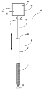
[0015] Figure 1 is a diagrammatic view of the present invention.
DETAILED DESCRIPTION
[0016] Referring now to the drawings submitted herewith, wherein various
elements depicted therein are not necessarily drawn to scale and wherein
through the views and figures like elements are referenced with identical
reference numerals, there is illustrated an insect capture device 100
constructed
according to the principles of the present invention.
[0017] An embodiment of the present invention is discussed herein with
reference
to the figures submitted herewith. Those skilled in the art will understand
that
the detailed description herein with respect to these figures is for
explanatory
purposes and that it is contemplated within the scope of the present invention
that alternative embodiments are plausible. By way of example but not by way
of
3
Date Recue/Date Received 2021-09-02
limitation, those having skill in the art in light of the present teachings of
the
present invention will recognize a plurality of alternate and suitable
approaches
dependent upon the needs of the particular application to implement the
functionality of any given detail described herein, beyond that of the
particular
implementation choices in the embodiment described herein. Various
modifications and embodiments are within the scope of the present invention.
[0018] It is to be further understood that the present invention is not
limited to the
particular methodology, materials, uses and applications described herein, as
these may vary. Furthermore, it is also to be understood that the terminology
used herein is used for the purpose of describing particular embodiments only,
and is not intended to limit the scope of the present invention. It must be
noted
that as used herein and in the claims, the singular forms "a", "an" and "the"
include the plural reference unless the context clearly dictates otherwise.
Thus,
for example, a reference to "an element" is a reference to one or more
elements
and includes equivalents thereof known to those skilled in the art. All
conjunctions used are to be understood in the most inclusive sense possible.
Thus, the word "or" should be understood as having the definition of a logical
"or" rather than that of a logical "exclusive or" unless the context clearly
necessitates otherwise. Structures described herein are to be understood also
to
refer to functional equivalents of such structures. Language that may be
construed to express approximation should be so understood unless the context
clearly dictates otherwise.
[0019] References to "one embodiment", "an embodiment", "exemplary
embodiments", and the like may indicate that the embodiment(s) of the
invention so described may include a particular feature, structure or
characteristic, but not every embodiment necessarily includes the particular
feature, structure or characteristic.
[0020] Referring in particular to Figures submitted as a part hereof, the
insect
capture device 100 includes a handle member 5. The handle member 5 includes
a first portion 6 and a second portion 7. The handle member 5 is manufactured
from a lightweight rigid material such as but not limited to metal. The first
4
Date Recue/Date Received 2021-09-02
portion 6 is formed to be hollow so as to slidably receive the second portion
7
therein. The second portion 7 is slidably coupled to the first portion 6 so as
to
provide an ability to extend the overall length of the handle member 5. While
no
particular is required, it is contemplated within the scope of the present
invention that the handle member 5 could be expanded from a length of twelve
inches to a length of twenty-four inches. A keeper 10 is operably coupled to
the
first portion 6 and is configured to provide locking of the second portion 7
in a
desired position. It should be understood by those skilled in the art that
numerous types of mechanical fasteners and coupling could be utilized to
provide adjustment of the second portion 7.
[0021] Secured to the second end 9 of the second portion 7 is swivel mount 15.
The
swivel mount 15 is secured to the second end 9 utilizing suitable durable
mechanical techniques. The swivel mount 15 provides adjustment of the head
member 30 both in rotational and pivotal movements. It should be understood
within the scope of the present invention that various types of mechanical
fasteners could be employed so as to provide the desired movement of the head
member 30.
[0022] Secured to the swivel mount 15 is the head member 30. The head member
30
is planar in manner and square in shape. While a square shape is desired in
the
preferred embodiment of the present invention, it is contemplated within the
scope of the present invention that the head member 30 could be provided in
alternate shapes. The head member 30 includes a central portion 35. The
central
portion 35 has an outer surface 36. The central portion 35 has an adhesive
disposed on the outer surface 36 wherein the adhesive will function to adhere
to
an insect ensuing the head member 30 being superposed the insect. It is
contemplated within the scope of the present invention that the central
portion
35 could have a removable substrate with adhesive secured thereto for
replacement thereof. Alternatively, as described herein, the central portion
35
would have an adhesive on the outer surface 36 operable to adhere to insects.
[0023] The head member 30 includes a circumferential border member 40. The
circumferential border member 40 is surroundably mounted to the central
Date Recue/Date Received 2021-09-02
portion 35 utilizing suitable techniques. The circumferential border member 40
is configured so as to extend outward from the central portion 35. The
formation
of the circumferential border member 40 inhibits the central portion 35 from
contacting a surface on which the head member 30 is placed. As the
circumferential border member 40 has a diameter that is larger than that of
the
thickness of the central portion 35, the central portion 35 will not contact a
surface on which the head member 30 has been superposed wherein an insect is
present. The circumferential border member 40 creates a void between the
surface on which the insect is located and the central portion 35. This void
facilitates the trapping of the insect upon the insect attempting to fly
resulting in
contact with the adhesive of the central portion 35. It is contemplated within
the
scope of the present invention that the head member 30 in a preferred
embodiment is four inches by four inches in size. The circumferential border
member 40 is manufactured from a soft non-marking plastic and is preferred to
have a diameter of approximately one-quarter of an inch.
[0024] A suction cup holder 50 is secured to the handle member 5. The suction
cup
holder is a conventional suction cup and is operable to secure the insect
capture
device 100 in a desired location when not in use. While illustrated at the end
of
the handle member 5, it should be understood within the scope of the present
invention that the suction cup holder 50 could be positioned in alternate
locations. Additionally, when not in use the central portion 35 can
effectively
provide trapping of flying insects similar to that of conventional fly paper.
The
first portion 6 of the handle member 5 further includes a foam grip 3. The
foam
grip 3 is provided for improved comfort and engagement of the handle member
5.
[0025] In the preceding detailed description, reference has been made to the
accompanying drawings that form a part hereof, and in which are shown by way
of illustration specific embodiments in which the invention may be practiced.
These embodiments, and certain variants thereof, have been described in
sufficient detail to enable those skilled in the art to practice the
invention. It is to
be understood that other suitable embodiments may be utilized and that logical
6
Date Recue/Date Received 2021-09-02
changes may be made without departing from the spirit or scope of the
invention. The description may omit certain information known to those skilled
in the art. The preceding detailed description is, therefore, not intended to
be
limited to the specific forms set forth herein, but on the contrary, it is
intended to
cover such alternatives, modifications, and equivalents, as can be reasonably
included within the spirit and scope of the appended claims.
7
Date Recue/Date Received 2021-09-02