Note: Descriptions are shown in the official language in which they were submitted.
88767083
HEMOSTASIS CLIP WITH COLLAPSIBLE CAPSULE
Inventors: Daniel CONGDON, Laurie A. LEHTINEN and Alex ROBERTS
Priority Claim
.. [0001] The present disclosure claims priority to U.S. Provisional Patent
Application Serial No.
62/853,303 filed May 28, 2019.
Field
[0002] The present disclosure relates to endoscopic devices and, in
particular, relates to
.. endoscopic clipping devices for treating tissue along the gastrointestinal
tract.
Background
[0003] During endoscopic gastrointestinal (GI) procedures, the patient may be
at risk of
perforation of a wall of the GI tact, or may require closure of the GI tract
wall as part of the
.. procedure. Hemostasis clips may be used for hemostasis of, for example,
mucosal/sub-mucosal
defects, bleeding ulcers, arteries, polyps, diverticula, along with closure of
luminal tract
perforations. Depending on the size of the defect, multiple clips may be
required.
Summary
[0004] The present disclosure relates to a clipping device, comprising a
capsule including a
longitudinal body and a cap mounted over a distal end thereof so that the cap
is movable relative
to the longitudinal body from a pre-deployed configuration to a deployed
configuration in which
the cap, is moved proximally relative to the longitudinal body to reduce a
length of the capsule.
A channel of the cap and a channel of the capsule being substantially aligned
with respect to one
another. The clipping device also includes a pair of clip arms, at least
proximal portions of
which are received within the channels of the cap and the longitudinal body so
that the clip arms
are movable relative to the capsule between an open configuration, in which
distal ends of the
clip arms are separated from one another, and a closed configuration, in which
the distal end of
1
Date Regue/Date Received 2023-03-22
CA 03129900 2021-08-10
WO 2020/242698
PCT/US2020/030308
the clip arms are drawn toward one another.
100051 In an embodiment, a distal end of the cap may include a shoulder for
abutting the distal
end of the longitudinal body to prevent further proximal movement of the cap
relative to the
longitudinal body.
[0006] In an embodiment, the clip arms may be biased toward the open
configuration so that, in
the closed configuration, the clip arms drawn toward one another via contact
with an interior
surface of one of the cap and the longitudinal body.
100071 In an embodiment, a proximal portion of the longitudinal body may
include locking
windows extending through a wall thereof.
100081 In an embodiment, proximal ends of the clip arms may include locking
tabs which are
configured to engage the locking windows of the longitudinal body when the
capsule is in the
deployed configuration.
[00091 In an embodiment, the cap may be coupled to the longitudinal body via a
shear pin
configured to fail when the predetermined force is exerted thereon.
100101 In an embodiment, the cap may be coupled to the longitudinal body via a
pin extending
from an interior surface thereof and through a slotted opening extending
through a wall along a
distal portion of the longitudinal body, the pin longitudinally slidable from
a distal end of the
slotted opening, in the pre-deployed configuration, to a proximal end of the
slotted opening, in
the deployed configuration.
100111 In an embodiment, the distal end of the slotted opening may be sized
and shaped to
correspond to a size and shape of the pin, the distal and proximal ends of the
slotted opening
connected via a middle portion having a width smaller than the distal end of
the slotted opening
2
CA 03129900 2021-08-10
WO 2020/242698
PCT/US2020/030308
so that when the predetermined force is exerted on the cap to move the capsule
from the pre-
deployed to the deployed configuration, one of the pin and the middle portion
deform to permit
the pin to be slid proximally along the slotted opening.
[0012] In an embodiment, at least one of the clip arms may include an engaging
feature
configured to engage a portion of the cap so that, when a predetermined
proximal force is
exerted thereon, the capsule is moved from the pre-deployed configuration to
the deployed
configuration.
[0013] The present disclosure also relates to device for treating a target
tissue, comprising a clip
including a capsule extending longitudinally from a proximal end to a distal
end and including a
channel extending therethrough. Proximal ends of a pair of clip arms are
slidably received
within the channel so that the pair of clip arms are movable between an open
configuration, in
which distal ends thereof are separated from one another, and a closed
configuration, in which
the distal ends thereof are moved toward one another. The capsule further
includes a cap
mounted over a distal end of a longitudinal body so that, when a predetermined
force is exerted
on the cap via engaging features of the clip arms, the cap is moved from a pre-
deployed
configuration to the deployed configuration, in which the cap is moved
proximally relative to the
longitudinal body to reduce a length of the capsule. A proximal portion of the
device is
configured to permit insertion of the clip through a working channel of an
endoscope. The
proximal portion includes a flexible shaft extending from a proximal end to a
distal end
configured to be releasably coupled to the proximal end of the capsule. A
control member
extends through the flexible shaft to a distal end releasably coupled to
proximal ends of the clip
arms so that moving the control member longitudinally relative to the flexible
shaft moves the
clip arms between the open and the closed configurations.
[0014] In an embodiment, a distal end of the cap may include a shoulder for
abutting the distal
end of the longitudinal body to prevent further proximal movement of the cap
relative to the
longitudinal body.
3
CA 03129900 2021-08-10
WO 2020/242698
PCT/US2020/030308
[0015] In an embodiment, the clip arms may be biased toward the open
configuration so that the
clip arms are constrained toward the closed configuration via an interior
surface of one of the cap
and the longitudinal body.
[0016] In an embodiment, the cap may be coupled to the longitudinal body via a
shear pin
configured to fail when the predetermined force is exerted thereon.
[0017] In an embodiment, the cap may be coupled to the longitudinal body via a
pin extending
from an interior surface thereof and through a slotted opening extending
through a wall along a
distal portion of the longitudinal body, the pin longitudinally slidable from
a distal end of the
slotted opening, in the pre-deployed configuration, to a proximal end of the
slotted opening, in
the deployed configuration.
[0018] In an embodiment, the distal end of the slotted opening may be sized
and shaped to
correspond to a size and shape of the pin, the distal and proximal ends of the
slotted opening
connected via a middle portion having a width smaller than the distal end of
the slotted opening
so that when the predetermined force is exerted on the cap to move the capsule
from the pre-
deployed to the deployed configuration, one of the pin and the middle portion
deform to permit
the pin to be slid proximally along the slotted opening.
[0019] The present disclosure also relates to a method for treating a target
tissue, comprising
inserting a clip device through a working channel of an endoscope to a target
site within a body
until the clip device extends distally past a distal end of the working
channel. The clip device
includes a capsule and a pair of clip arms slidably received therein. The
capsule further includes
a cap mounted over a distal end of a longitudinal body. The clip device is
moved between an
open configuration, in which distal ends of the clip aims are separated from
one another, and a
closed configuration, in which the distal ends of the clip arms are drawn
toward one another,
until a target tissue is received between the distal ends as desired. The clip
arms are drawn
4
CA 03129900 2021-08-10
WO 2020/242698
PCT/US2020/030308
proximally into the capsule to move the clip toward the closed configuration
to grip the target
tissue between the clip arms. The clip is moved from a pre-deployed
configuration toward a
deployed configuration which reduces a length of the capsule by moving the
clip arms further
proximally relative to the so that an engaging feature of the clip arms
engages the cap and exerts
a predetemiined proximal force thereon to move the cap proximally relative to
the longitudinal
body.
Brief Description of the Figures
100201 Fig. lshows a longitudinal cross-sectional view of the device of Fig.
1, in the pre-
deployed configuration;
Fig. 2 shows a longitudinal cross-sectional view of the device of Fig. 1, in a
deployed
configuration;
Fig. 3 shows a longitudinal side view of a device according to an exemplary
embodiment
of the present disclosure;
Fig. 4 shows a longitudinal side view of a capsule of the device of Fig. 1, in
the pre-
deployed configuration;
Fig. 5 shows a longitudinal side view of the capsule of the device of Fig. 1,
in the
deployed configuration;
Fig. 6 shows an enlarged partially transparent view of a portion of the
capsule of the
device of Fig. 1, in the pre-deployed configuration;
Fig. 7 shows an enlarged partially transparent view of the capsule of the
device of Fig. 1,
in the deployed configuration;
5
CA 03129900 2021-08-10
WO 2020/242698
PCT/US2020/030308
Fig. 8 shows an enlarged partially transparent view of a portion of a capsule
of a device
according to an alternate embodiment of the present disclosure, in a pre-
deployed configuration;
and
Fig. 9 shows an enlarged partially transparent view of a portion of the
capsule of Fig. 8,
in a deployed configuration.
Detailed Description
[002111 The present disclosure may be further understood with reference to the
following
.. description and the appended drawings, wherein like elements are referred
to with the same
reference numerals. The present disclosure is directed to an endoscopic
clipping device for
treating tissue perforations, defects and/or bleeds. In some cases, a shorter
deployed clip may be
preferred to improve visualization of the target site and to allow better
maneuverability when
placing multiple clips. Exemplary embodiments of the present disclosure
describe a clip
comprising clip arms, proximal ends of which are slidably received within a
capsule to move the
clip between an open configuration and a closed configuration to clip a target
tissue, as desired.
As the clip is deployed over the target tissue in the closed configuration,
the capsule collapses to
reduce a length of the deployed clip, improving visibility of a target site
and maneuverability
when placing multiple clips. It should be noted that the terms proximal and
distal, as used
herein, are intended to refer to a direction toward (proximal) and away from
(distal) a user of the
device.
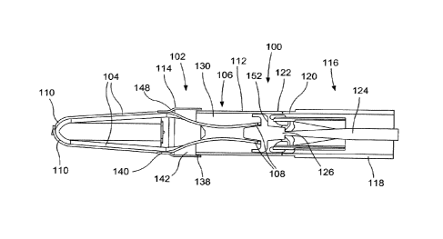
[0022] As shown in Figs. 1 - 7, a clipping device 100 for treating tissue
defects comprises a clip
102 including a pair of clip arms 104, proximal ends 108 of which are slidably
received within a
capsule 106 so that the clip 102 may move between an open configuration, in
which distal ends
110 of the clip arms 102 are separated from one another, and a closed
configuration, in which the
distal ends 110 are drawn toward one another. The capsule 106 further
comprises a longitudinal
body 112 and a cap 114 coupled to one another and movable relative to one
another from a pre-
deployed configuration to a deployed configuration. In one embodiment, the cap
114 may be
6
CA 03129900 2021-08-10
WO 2020/242698
PCT/US2020/030308
coupled to the longitudinal body 112 via, for example, a shear pin 132, which
breaks or separates
to move the capsule from the pre-deployed to the deployed configuration. As
the capsule 106 is
moved from the pre-deployed to the deployed configuration, the cap 114 moves
relative to the
longitudinal body 112 to reduce a length of the capsule 106 upon deployment.
The device 100 is
releasably coupled to a proximal portion 116 facilitating insertion of the
device 100 to a target
site, connecting the clip 102 to actuators accessible to a user (i.e., outside
the body) to permit the
user to control movement of the device 100 between the open and closed
configurations and to
deploy the device clip 102 over target tissue. The proximal portion 116 may
include, for
example, a flexible shaft 118 extending from a proximal end connected to a
handle member (not
shown) that remains outside the body, the handle including controls for moving
and deploying
the device 100 to a distal end 120 releasably coupled to a proximal end 122 of
the capsule 106.
The proximal portion 116 also includes a control member 124 extending from a
proximal end
connected to the controls of the handle member to a distal end 126 connected
to the proximal
ends 108 of the clip arms 102.
[0023] As described above, the capsule 106 includes the longitudinal body 112
and the cap 114.
The longitudinal body 112 extends from the proximal end 122 to a distal end
128 and includes a
channel 130 extending therethrough. In one embodiment, the proximal end 122 is
configured to
be releasably coupled to the distal end 120 of the flexible shaft 118. For
example, the proximal
end 122 may include tabs 134 that are crimped radially inward to engage a
corresponding portion
of a bushing at the distal end 120 of the flexible shaft 118. The longitudinal
body 112 may also
include locking windows 136 extending laterally through a wall thereof or
other structures for
engaging locking tabs 150 of the clip arms 104, as will be described in
further detail below.
[0024] In one embodiment, the cap 114 is mounted over the distal end 128 so
that the cap 114 is
movable relative to the longitudinal body 112 from the pre-deployed to the
deployed
configuration. The cap 114 also extends longitudinally from a proximal end 138
to a distal end
140 with a channel 142 extending longitudinally therethrough so that channels
142, 130 of the
cap 114 and the longitudinal body 112 are aligned to permit the clip arms 104
to slide
7
CA 03129900 2021-08-10
WO 2020/242698
PCT/US2020/030308
longitudinally therein. In the pre-deployed configuration, the cap 114 is in a
distal-most position
relative to the longitudinal body 112. As the capsule 106 is moved from the
pre-deployed to the
deployed configuration, the cap 114 moves proximally relative to the
longitudinal body 112 so
that a length of the capsule 106 in the deployed configuration is shorter than
a length of the
capsule 106 in the pre-deployed configuration. In one embodiment, the distal
end 140 of the cap
114 includes a shoulder 148 configured to engage the distal end 128 of the
longitudinal body 112
to prevent the distal end 128 of the longitudinal body 112 from moving
distally therepast. In
other words, when the shoulder 148 engages the distal end 128 of the
longitudinal body 112, the
cap 114 is in a proximal-most position relative to the longitudinal body 112
and defines a
minimum length of the capsule 106.
[00251 The cap 114 may be coupled to the distal end 128 of the longitudinal
body 112 in any of
a variety of ways. In one embodiment, the cap 114 may be overmolded to the
longitudinal body
112. In one example, as shown in Figs. 6-7, the cap 114 is overmolded to the
distal end 128 of
the longitudinal body 112 via a shear pin 132, in the pre-deployed
configuration. The shear pin
132 is configured to break and/or separate when a predetermined force is
exerted thereon. In one
embodiment, when the clip arms 104 are drawn proximally relative to the
capsule 106 to lock
and deploy the clip 102, as will be described in further detail below, a
portion of the one or both
clip arms 104 engages the distal end 140 of the cap 114 so that a proximal
force is exerted
thereon. The proximal force exerted on the cap 114 breaks the shear pin 132 so
that the cap 114
is freed to move proximally with respect to the longitudinal body 112, from
the pre-deployed to
the deployed configuration.
100261 Each of the clip arms 104 extends from the proximal end 108 to the
distal end 110. As
described above, proximal portions of the clip arms 104 are slidably received
within the channels
130, 142 of the longitudinal body 112 and the cap 114 of the capsule 106. In
some
embodiments, the proximal ends 108 of the clip aims 104 are slidably received
within the
longitudinal body 112 to move the clip 102 between the open and closed
configurations. For
example, as described above, the proximal ends 108 of the clip ai
_______________ us 104 may be coupled to the
8
CA 03129900 2021-08-10
WO 2020/242698
PCT/US2020/030308
control member 124 (directly or indirectly) so that the clip arms 104 may be
moved between the
open and closed configurations via manipulation of the control member 124. In
one
embodiment, the clip arms 104 are biased toward the open configuration so
that, in the closed
configuration, the clip arms 104 are constrained toward one another via an
interior surface of the
cap 114 and/or the longitudinal body 112. When the clip arms 104 are moved
distally to extend
further out of the capsule 106, the clip arms 114 revert to their biased open
configuration.
[00271 Each of the clip arms 104 also includes an engaging feature 144
configured to engage a
portion of the cap 114 to exert a proximal force thereon when the clip arms
104 are drawn
proximally with respect to the capsule 106. In one embodiment, as shown in
Fig. 3, the engaging
features 144 extend from a portion of the clip arms 104 so that, when the clip
arms 104 are
drawn proximally relative to the capsule 106, the engaging features 144 abut a
portion of a distal
face 146 of the cap 114. The engaging features 144 are positioned along the
clip arms 104 so
that, when the engaging features 144 engage the cap 114, the clip arms 104 are
drawn toward the
closed configuration. in one example, the engaging features 144 are configured
as wings
extending from longitudinal edges of the clip arms 104.
100281 Proximal ends 108 of the clip arms 104 also include locking tabs 150
extending
therefrom. The proximal ends 108 in this embodiment are biased outward, away
from a
centerline of the capsule 106, but are restrained via the distal end 126 of
the control member 124
until the clip 102 is being deployed. As will be described in further detail
below, when it is
desired to lock the clip 102 in the closed configuration, the clip arms 104
are moved proximally
relative to the capsule 106 until the proximal ends 108 of the clip ainis 104
are released from the
control member 124 and the locking tabs 150 are permitted to spring outward
and engage the
locking windows 136 of the longitudinal body 112.
100291 According to an exemplary method utilizing the device 100, the clip 102
is inserted
through, for example, a working channel of an endoscope to a target site
within a body while the
handle member remains exterior to the body. The clip 102 is inserted through
the working
9
CA 03129900 2021-08-10
WO 2020/242698
PCT/US2020/030308
channel in the closed configuration. Once the clip 102 has reached the target
site, the clip arms
104 are extended distally out of the capsule 106 and move under their natural
bias toward the
open configuration so that target tissue may be received between the clip arms
104. The clip 102
may be moved between the open and closed configurations by extending the
control member 124
distally or withdrawing it proximally until a desired portion of target tissue
is positioned between
the clip arms 104, as desired. At this point, the clip 102 is drawn into the
closed configuration to
grip this portion of target tissue between the distal ends 110 of the clip
arms 104 as desired. The
clip 102 may be moved toward the locked configuration by, for example, drawing
the control
member 124 further proximally relative to the capsule 106 until the engaging
features 144
engage the cap 114, as described above, exerting a proximal force on the cap
114 to break,
separate or otherwise cause the shear pin 132 to fail. Upon
breaking/separating of the shear pin
132, the cap 114 moves proximally relative to the longitudinal body 112 from
the pre-deployed
configuration to the deployed configuration, collapsing the capsule 106 and
reducing a length of
the capsule 106.
100301 When the shoulder 148 of the cap 114 contacts the distal end 128 of the
longitudinal body
112 and prevents the cap 114 from moving further proximally relative to the
longitudinal body
112, the clip 102 is locked and deployed. According to one example, when the
shoulder 148
engages the longitudinal body 112, the proximal force on the control member
124 causes the
control member 124 to release from the proximal ends 108 of the clip arms 104,
allowing the
proximal ends 108 to revert to their biased configuration so that the locking
tabs 150 engage the
locking windows 136, thereby locking the clip 102 in the collapsed, closed
configuration. The
control member 124 is drawn proximally until an enlarged portion 152 at the
distal end 126 of
the control member 124 is positioned within the proximal end 122 of the
longitudinal body 112
of the capsule 106 to move the inwardly crimped tabs 134 outward (i.e., away
from a centerline
of the capsule 106), out of engagement with, for example, the bushing at the
distal end 120 of the
flexible shaft 118. Further proximal motion of the control member 124
separates the control
member 124 from the clip 102, freeing the clip 102 from the proximal portion
of the device 100
and freeing it to remain in the body as the rest of the device 100 is removed
from the body.
CA 03129900 2021-08-10
WO 2020/242698
PCT/US2020/030308
[0031] Although the exemplary embodiments show and describe a specific
deployment
mechanism, it will be understood by those of skill in the art that the clip
102 may be deployed
via any of a number of deployment mechanisms so long as the capsule 106
collapses to reduce a
length thereof during the deployment process. Specifically, as described
above, the capsule 106
is collapsed via the proximal motion of the cap 114 relative to the
longitudinal body. Although
the exemplary embodiment describes and shows mounting of the cap 114 over the
distal end 128
of the longitudinal body 112 in the pre-deployed configuration via a shear pin
132, it will be
understood by those of skill in the art that the cap 114 may be temporarily
fixed relative to the
longitudinal body 112 in the pre-deployed configuration and moved toward the
deployed
configuration via any of a number of mechanisms.
[0032] For example, as shown in Figs. 8-9, a capsule 206 may be substantially
similar to the
capsule 106 described above, and may be utilized in place of the capsule 106
in the device 100.
Similarly to the capsule 106, the capsule 206 includes a cap 214 mounted over
a distal end 228
of a longitudinal body 212 and movable relative thereto from a pre-deployed
configuration to a
deployed configuration. The cap 214 and the longitudinal body 212 may be
substantially similar
to the cap 114 and longitudinal body 112 described above with respect to the
capsule 106. Rather
than being mounted over the longitudinal body in the pre-deployed
configuration via a shear pin,
however, the cap 214 is coupled to the longitudinal body 212 via a pin 232 and
slot 254.
[0033] In one embodiment, a distal portion of the longitudinal body 112
includes the slot 254
extending longitudinally through a wall thereof. The pin 232 extends from an
interior surface of
the cap 214 and through the slot 254 to couple the cap 214 to the longitudinal
body 112. In a
pre-deployed configuration, the pin 232 extends through a distal portion 256
of the slot 254
while in the deployed configuration, the pin 232 extends through the proximal
portion 258 of the
slot 254. The distal and proximal portions 256, 258 of the slot 254 are sized
and shaped to
correspond to a size and shape of the pin 232 received therein. A middle
portion 260 of the slot
254 connecting the distal and proximal portions 256, 258 has a width smaller
than a width of
11
CA 03129900 2021-08-10
WO 2020/242698
PCT/US2020/030308
each of the distal and proximal portions 256, 258. In other words, where the
pin 232 is
cylindrical, a width of the middle portion 260 is smaller than a diameter of
the pin 232 so that, to
be moved from the pre-deployed to the deployed configuration, a predetermined
force must be
exerted on the pin 232, causing one of the pin 232 and/or the middle portion
260 to elastically
deform allowing the pin 232 to slide along the middle portion 260 from the
distal portion 256 to
the proximal portion 258.
100341 The capsule 206 may be utilized in substantially the same manner as the
capsule 106.
For example, as described above, in the pre-deployed configuration, the pin
232 is in the distal
portion 256 of the slot 254 so that the cap 214 is in a distal-most position
relative to the
longitudinal body 212. Once the clip 102 has gripped a target tissue as
desired, however, the clip
arms 104 are drawn farther proximally relative to the capsule 206 until the
engaging features 144
of the clip arms 104 engage the cap 214, exerting a proximal force on the cap
214 which deforms
the pin 232 or the middle portion 260 of the slot 254 permitting the pin 232
to slide from the
distal portion 256, through the middle portion 260 and to the proximal portion
254. When the
pin 232 is received within the proximal portion 254, the cap 214 is in the
proximal-most position
relative to the longitudinal body 212, in the collapsed configuration. As
described above, the
clip 102 may then be locked and deployed, in the collapsed and closed
configuration, as will be
understood by those of skill in the art.
[0035] It will be apparent to those skilled in the art that various
modifications may be made in
the present disclosure, without departing from the scope of the disclosure.
12