Note: Descriptions are shown in the official language in which they were submitted.
WO 2020/183468
PCT/11,2020/050290
DEVICES, SYSTEMS AND METHODS FOR AUTOMATIC EXTRACTION, STORAGE
AND ENCAPSULATION OF FATTY COMPOUNDS
FIELD OF THE INVENTION
[0001] The present invention relates to the field of extraction of fatty
compounds, and more
particularly, to automatic devices, systems and for methods for extraction,
storage and encapsulation
of fatty compounds.
BACKGROUND OF THE INVENTION
[0002] Fatty compounds are widely used, for example, in the food industry,
pharmaceutical industry,
cosmetics industry and the like. Currently there is a trend of extracting
fatty compounds for personal
use, for example for the treatment of medical and psychological disorders,
health nutrition, preparation
of natural cosmetic products and the like.
SUMMARY OF THE INVENTION
[0003] Some embodiments may provide a device for automatic extraction, storage
and encapsulation
of fatty compounds, the device may include: an extraction unit configured to
provide a liquid mixture
comprising fatty compounds extracted from biological material and a liquid
solvent; an evaporation
and reaction unit; a storage unit that may include one or more storage outlet
ports; fluid conduits
connecting the evaporation and reaction unit with the extraction unit and the
storage unit with the
evaporation and reaction unit; and a controller configured to: control
delivery of the liquid mixture
from the extraction unit to the evaporation and reaction unit; control
evaporation of the solvent from
the liquid mixture in the evaporation and reaction unit; control delivery of
the liquid mixture from the
evaporation and reaction unit to the storage unit; detect safe connection of
each of at least one of one
or more capsules to one of the one or more storage outlet ports of the storage
unit; and control filling
of at least one of the one or more connected capsules with the liquid mixture
from the storage unit.
[0004] In some embodiments, the device may include: a solvent supply unit; and
fluid conduits
connecting the solvent supply unit with the extraction unit; wherein the
controller is configured to
control delivery of the liquid solvent from the solvent supply unit to the
extraction unit.
[0005] In some embodiments, the device may include a diluting liquid supply
unit; and fluid conduits
connecting the diluting liquid supply unit with the evaporation and reaction
unit; wherein the
controller is configured to control delivery of a diluting liquid from the
diluting liquid supply unit to
the evaporation and reaction unit.
1
WO 2020/183468
PCT/11,2020/050290
[0006] In some embodiments, the controller is configured to: receive user's
preferences concerning
the liquid mixture to be produced; determine operation parameters based on the
user's preferences;
and control the delivery, the evaporation and the filling based on the
determined operation parameters.
[0007] In some embodiments, the extraction unit may include: a filter
configured to separate the
biological material from the liquid mixture; and an extraction chamber
configured to accommodate
the liquid mixture; wherein the controller is configured to control
circulation of the liquid mixture by
controlling delivery of the liquid mixture from a downstream portion of the
extraction chamber to at
least one of: the filter and an upstream portion of the extraction chamber.
[0008] In some embodiments, the filter may include: a filtering compartment
adapted to receive and
accommodate the biological material; and one or more conduits comprising
multiple sprinkling holes,
the one or more conduits are connectable to a solvent supply unit and adapted
to deliver the liquid
solvent and to sprinkle the liquid solvent into the filtering compartment
through the multiple
sprinkling holes.
[0009] In some embodiments, the filtering compartment comprises an aperture
through which the
biological material may be introduced into the filtering compartment; the
device comprises a covering
adapted to removably cover the aperture; and at least one of the one or more
conduits is attached to
the covering.
[0010] In some embodiments, at least the filtering compartment of the filter
is deformable; the device
may include a filter deforming mechanism; and the controller is configured to
control the filter
deforming mechanism to deform at least the filtering compartment of the filter
to squeeze the
biological material and to remove residuals of the liquid mixture from the
biological material.
[0011] In some embodiments, the evaporation and reaction unit may include: an
evaporation and
reaction chamber; and a heating element; wherein the controller is configured
to at least one of: control
the heating element to heat the liquid mixture in the evaporation and reaction
chamber above a boiling
temperature of the liquid solvent to evaporate the solvent from the liquid
mixture; and control the
heating element to heat the liquid mixture above a specified temperature value
to induce at least one
component of the liquid mixture undergo a specified chemical reaction.
[0012] In some embodiments, the evaporation and reaction chamber tapers in a
direction extending
from an upstream portion to a downstream portion of the evaporation and
reaction chamber.
[0013] In some embodiments, the evaporation and reaction chamber comprises a
liquid mixture
compartment at the downstream portion thereof, the liquid mixture compartment
is adapted to
accommodate the liquid mixture that has not been evaporated; and a volume of
the liquid mixture
2
WO 2020/183468
PCT/11,2020/050290
compartment is predetermined based on a maximal volume of the liquid mixture
that may be produced
by the device during one operational cycle.
[0014] In some embodiments, the heating element is disposed adjacent to the
liquid mixture
compartment.
[0015] In some embodiments, the controller is configured to control a cleaning
of the device, the
controller is configured to: control delivery of the liquid solvent to the
extraction unit; control delivery
of the liquid solvent from the extraction unit to the evaporation unit; and
control evaporation of the
liquid solvent in the evaporation and reaction unit.
[0016] In some embodiments, the controller is configured to: control delivery
of the liquid solvent
from the evaporation and reaction unit to the storage unit; detect safe
connection of a dedicated
cleaning capsule to the storage unit; and control filling of the dedicated
cleaning capsule with the
liquid solvent from the storage unit.
[0017] In some embodiments, the device may include a housing, the housing may
include: a barrier
structure that divides an interior of the housing into a first sub-zone and a
second sub-zone; wherein
the first sub-zone comprises is free of any electrical components; and wherein
the barrier structure is
sealed to prevent transfer of flammable vapors from the first sub-zone to the
second sub-zone.
[0018] Some embodiments may provide a kit comprising the device as described
above and one or
more capsules removably connectable to the one or more storage outlet ports of
the storage unit and
adapted to be filled with the liquid mixture from at least one of the one or
more storage containers.
[0019] In some embodiments, each of the one or more capsules may include: a
flexible reservoir that
may include: an inlet removably connectable to the storing unit and configured
to enable filling of the
liquid mixture into the reservoir, and an outlet configured to enable outflow
of the liquid mixture from
reservoir upon compression thereof; and a pressure applicator configured to
apply pressure to the
flexible reservoir to press the reservoir.
[0020] In some embodiments, the pressure applicator of each of the one or more
capsules may include:
a first arm; a second arm; and an arms-connector connecting the first arm and
the second arm at one
of their ends; the reservoir is disposed between the first arm and the second
arm and adapted to be
pressed by the first arm and the second arm when the arms are pressed against
each other; the first
arm and the second arm are made of elastic material and return to their
initial state when the pressure
thereon is released.
[0021] In some embodiments, the first arm and the second arm of at least one
of the one or more
capsules comprise matching wave-like surfaces facing each other.
3
WO 2020/183468
PCT/11,2020/050290
[0022] In some embodiments, the fffst arm and the second arm of at least one
of the one or more
capsules comprises a first protrusion and a second protrusion, respectively,
at free ends thereof, the
first protrusion and the second protrusion are adapted to contact when the
first arm and the second
arm are pressed against each other.
[0023] In some embodiments, each of the one or more capsules comprises a
capsule identifier
configured to store a capsule-related information.
[0024] Some embodiments may provide a device for automatic extraction, storage
and encapsulation
of fatty compounds, the device may include: a solvent supply unit configured
to at least one of supply
and store a liquid solvent; an extraction unit configured to extract fatty
compounds from biological
material using the liquid solvent to provide a liquid mixture; a diluting
liquid supply unit configured
to at least one of supply and store a diluting liquid; an evaporation and
reaction unit; a storage unit
that may include one or more storage outlet ports; fluid conduits connecting
the solvent supply unit
with the extraction unit, the evaporation and reaction unit with the
extraction unit and the storage unit
with the evaporation and reaction unit and the diluting liquid supply unit
with the evaporation and
reaction unit; and a controller configured to: receive user's preferences
concerning the liquid mixture
to be produced; determine operation parameters based on the user's
preferences; control delivery of
the liquid solvent from the solvent supply unit to the extraction unit based
on the determined operation
parameters; control extraction of the fatty compounds in the extraction unit
based on the determined
operation parameters; control delivery of the liquid mixture from the
extraction unit to the evaporation
and reaction unit based on the determined operation parameters; control
evaporation of the solvent
from the liquid mixture in the evaporation and reaction unit based on the
determined operation
parameters; control delivery of a diluting liquid from the diluting liquid
supply unit to the evaporation
and reaction unit based on the determined operation parameters; control
delivery of the liquid mixture
from the evaporation and reaction unit to the storage unit based on the
determined operation
parameters; detect safe connection of each of at least one of one or more
capsules to one of the one or
more storage outlet ports of the storage unit; and control filling of at least
one of the one or more
connected capsules with the liquid mixture from the storage unit based on the
determined operation
parameters.
[0025] Some embodiments may provide an evaporation and reaction unit that may
include: an
evaporation and reaction chamber configured to receive at least one of a
liquid mixture and a diluting
liquid, the evaporation and reaction chamber tapers in a direction extending
from an upstream portion
to a downstream portion thereof and may include a liquid mixture compartment
at the downstream
portion thereof, the liquid mixture compartment is adapted to accommodate at
least one of the liquid
4
WO 2020/183468
PCT/11,2020/050290
mixture and the diluting liquid that has not been evaporated; and a
controllable heating element
disposed adjacent to the liquid mixture compartment of the evaporation and
reaction chamber.
[0026] Some embodiments may provide a device for storage and encapsulation of
fatty compounds,
the device may include: one or more storage containers each adapted to
accommodate a liquid mixture
containing fatty compounds; one or more storage outlet ports in fluid
communication with at least one
of the one or more storage containers; and a controller configured to: receive
user's preferences
concerning one or more desired liquid mixture; detect safe connection of each
of at least one of one
or more capsules to one of the one or more the storage outlet ports; and
control filling of at least one
of the one or more connected capsules with at least one of the one or more
desired liquid mixtures
based on the user's preferences.
[0027] Some embodiments may provide a kit that may include the device storage
and encapsulation
of fatty compounds as described above and one or more capsules removably
connectable to the one
or more storage outlet ports and adapted to be filled with the liquid mixture
from at least one of the
one or more storage containers.
[0028] Some embodiments may provide a capsule for encapsulation of a liquid
mixture, the capsule
may include: a flexible reservoir that may include: an inlet removably
connectable to the storing unit
and configured to enable filling of the liquid mixture into the reservoir, and
an outlet configured to
enable outflow of the liquid mixture from reservoir upon compression thereof;
and a pressure
applicator configured to apply pressure to the flexible reservoir to press the
reservoir.
[0029] In some embodiments, the pressure applicator may include: a first arm;
a second arm; and an
arms-connector connecting the first arm and the second arm at one of their
ends; the reservoir is
disposed between the first arm and the second arm and adapted to be pressed by
the first arm and the
second arm when the arms are pressed against each other; the first arm and the
second arm are made
of elastic material and return to their initial state when the pressure
thereon is released_
[0030] In some embodiments, the first arm and the second arm comprise matching
wave-like surfaces
facing each other.
[0031] In some embodiments, the first arm may include a first protrusion and
the second arm
comprises a second protrusion at free ends thereof, the first protrusion and
the second protrusion are
adapted to contact when the first arm and the second arm are pressed against
each other.
[0032] In some embodiments, the capsule may include a capsule identifier
configured to store a
capsule-related information_
[0033] Some embodiments may provide a filter that may include: a filtering
compartment; and one or
more conduits comprising multiple sprinkling holes, the one or more conduits
are connectable to a
5
WO 2020/183468
PCT/11,2020/050290
solvent supply unit and adapted to deliver the liquid solvent and to sprinkle
the liquid solvent into the
filtering compartment through the multiple sprinkling holes.
[0034] In some embodiments, the filtering compartment comprises an aperture
through which the
biological material may be introduced into the filtering compartment and
wherein at least one of the
one or more conduits is attached to the covering.
[0035] In some embodiments, at least the filtering compartment of the filter
is defortnable.
[0036] Some embodiments may provide a method of automatic extraction, storage
and encapsulation
of fatty compounds, the method may include: receiving, by a device, user's
preferences concerning a
liquid mixture to be produced by the device; determining, by the device,
operation parameters based
on the user's preferences; controlling, by the device, a supply of a liquid
solvent based on the
determined operation parameters; controlling, by the device, extraction of
fatty compounds from
biological material using the liquid solvent, based on the determined
operation parameters, to provide
a liquid mixture containing fatty compounds and the liquid solvent;
controlling, by the device,
evaporation of the solvent from the liquid mixture, based on the determined
operation parameters; and
controlling, by the device, filling of one or more capsule with the liquid
mixture, based on the
determined operation parameters.
[0037] In some embodiments, the method may include controlling, by the device,
circulation of at
least one of the liquid mixture and the liquid solvent, based on the
determined operation parameters.
[0038] In some embodiments, the method may include controlling, by the device,
a temperature of at
least one of the liquid solvent being supplied and the liquid mixture being
circulated, based on the
determined operation parameters.
[0039] In some embodiments, the method may include controlling, by the device,
squeezing of the
biological material to remove residuals of the liquid mixture from the
biological material.
[0040] In some embodiments, the method may include controlling, by the device,
dilution of the liquid
mixture with a diluting liquid, based on the determined operation parameters.
[0041] In some embodiments, the method may include controlling, by the device,
a specified chemical
reaction of at least one component of the liquid mixture, based on the
determined operation
parameters.
[0042] In some embodiments, the method may include controlling, by the device,
cleaning of the
device.
[0043] These, additional, and/or other aspects and/or advantages of the
present invention are set forth
in the detailed description which follows; possibly inferable from the
detailed description; and/or
learnable by practice of the present invention.
6
WO 2020/183468
PCT/11,2020/050290
BRIEF DESCRIPTION OF THE DRAWINGS
[0044] For a better understanding of embodiments of the invention and to show
how the same can be
carried into effect, reference will now be made, purely by way of example, to
the accompanying
drawings in which like numerals designate corresponding elements or sections
throughout.
[0045] In the accompanying drawings:
[0046] Fig. 1 which is a block diagram of a device for automatic extraction,
storage and encapsulation
of fatty compounds, according to some embodiments of the invention;
[0047] Fig. 2 is a block diagram of a more detailed aspect of a device for
automatic extraction, storage
and encapsulation of fatty compounds, according to some embodiments of the
invention;
[0048] Fig. 3A which is a schematic illustration of a filter, according to
some embodiments of the
invention;
[0049] Fig. 3B is a schematic illustration of a filtering unit including two
or more filters, according
to some embodiments of the invention;
[0050] Fig. 3C is a schematic illustration of a filter including a housing,
according to some
embodiments of the invention;
[0051] Fig. 4 is a schematic illustration of a deformable filter, according to
some embodiments of the
invention;
[0052] Fig. 5 is a schematic illustration of an evaporation and reaction unit,
according to some
embodiments of the invention;
[0053] Figs. 6A, 6B, 6C and 6D are schematic illustrations of one embodiment
of a device automatic
extraction, storage and encapsulation of fatty compounds, according to some
embodiments of the
invention;
[0054] Fig. 7 is a schematic illustration of a first embodiment of a capsule,
according to some
embodiments of the invention;
[0055] Fig. 8 is a schematic illustration of a second embodiment of a capsule,
according to some
embodiments of the invention;
[0056] Fig. 9 is a block diagram of a device for storage and encapsulation of
fatty compounds,
according to some embodiments of the invention;
[0057] Fig. 10 is a flowchart of a method of automatic extraction, storage and
encapsulation of fatty
compounds, according to some embodiments of the invention;
[0058] Figs. 11A and 11B schematically illustrate, according to an exemplary
embodiment, a front
view and a front perspective view, respectively, of an extracting-storing-
distributing apparatus.
7
WO 2020/183468
PCT/11,2020/050290
[0059] Fig. 12 schematically illustrates, according to an exemplary
embodiment, a front view of an
apparatus for extracting fatty compounds from a biological material, further
showing direction of flow
of fluids in the apparatus.
[0060] Fig. 13 schematically illustrates, according to an exemplary
embodiment, a front view of an
apparatus for extracting fatty compounds from a biological material, further
showing positions of
sensors and controllers in the apparatus.
[0061] Fig. 14 schematically illustrates, according to an exemplary
embodiment, a front view of an
extracting apparatus.
[0062] Figs. 15A and 15B schematically illustrate, according to an exemplary
embodiment, a front
view and a side view, respectively, of a storing and distributing apparatus.
[0063] Figs. 16A, 16B, 16C and 16D schematically illustrate, according to an
exemplary
embodiment, a front view, a front cross-section view, a front perspective view
and an upper view,
respectively, of an evaporator.
[0064] Fig. 17A schematically illustrates, according to an exemplary
embodiment, a side cross-
section view of a capsule in a resting state.
[0065] Fig. 17B schematically illustrates, according to an exemplary
embodiment, a side cross-
section view of a capsule in an expelling state.
[0066] Fig. 18A schematically illustrates, according to an exemplary
embodiment, a side cross-
section view of a full-expel capsule in a resting state.
[0067] Fig. 18B schematically illustrates, according to an exemplary
embodiment, a side cross-
section view of a full-expel capsule in an expelling state.
[0068] Fig. 19A schematically illustrates, according to an exemplary
embodiment, a side cross-
section view of a doze-expel capsule in a resting state_
[0069] Fig. 19B schematically illustrates, according to an exemplary
embodiment, a side cross-
section view of a dose-expel capsule in an expelling state.
[0070] It will be appreciated that, for simplicity and clarity of
illustration, elements shown in the
figures have not necessarily been drawn to scale. For example, the dimensions
of some of the elements
may be exaggerated relative to other elements for clarity. Further, where
considered appropriate,
reference numerals may be repeated among the figures to indicate corresponding
or analogous
elements.
DETAILED DESCRIPTION OF THE INVENTION
8
WO 2020/183468
PCT/11,2020/050290
[0071] In the following description, various aspects of the present invention
are described. For
purposes of explanation, specific configurations and details are set forth in
order to provide a thorough
understanding of the present invention. However, it will also be apparent to
one skilled in the art that
the present invention can be practiced without the specific details presented
herein. Furthermore, well
known features can have been omitted or simplified in order not to obscure the
present invention.
With specific reference to the drawings, it is stressed that the particulars
shown are by way of example
and for purposes of illustrative discussion of the present invention only and
are presented in the cause
of providing what is believed to be the most useful and readily understood
description of the principles
and conceptual aspects of the invention. In this regard, no attempt is made to
show structural details
of the invention in more detail than is necessary for a fundamental
understanding of the invention, the
description taken with the drawings making apparent to those skilled in the
art how the several forms
of the invention can be embodied in practice.
[0072] Before at least one embodiment of the invention is explained in detail,
it is to be understood
that the invention is not limited in its application to the details of
construction and the arrangement of
the components set forth in the following description or illustrated in the
drawings. The invention is
applicable to other embodiments that can be practiced or carried out in
various ways as well as to
combinations of the disclosed embodiments. Also, it is to be understood that
the phraseology and
terminology employed herein is for the purpose of description and should not
be regarded as limiting.
[0073] Unless specifically stated otherwise, as apparent from the following
discussions, it is
appreciated that throughout the specification discussions utilizing terms such
as "processing",
"computing", "calculating", "determining", "enhancing" or the like, refer to
the action and/or
processes of a computer or computing system, or similar electronic computing
device, that
manipulates and/or transforms data represented as physical, such as
electronic, quantities within the
computing system's registers and/or memories into other data similarly
represented as physical
quantities within the computing system's memories, registers or other such
information storage,
transmission or display devices. Any of the disclosed modules or units can be
at least partially
implemented by a computer processor.
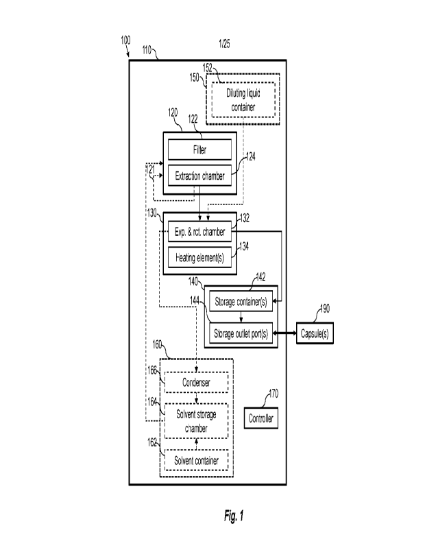
[0074] Reference is now made to Fig. 1, which is a block diagram of a device
100 for automatic
extraction, storage and encapsulation of fatty compounds, according to some
embodiments of the
invention.
[0075] In some embodiments, device 100 may include a housing 110. Housing 110
may be adapted
to accommodate at least some units of device 100 and/or removably accommodate
at least some units
of device 100.
9
WO 2020/183468
PCT/11,2020/050290
[0076] Device 100 may include an extraction unit 120. In some embodiments,
extraction unit 120
may include a filter 122 and an extraction chamber 124. Extraction unit 120
may receive a biological
material and a liquid solvent. For example, the biological material may
include at least a portion of a
Cannabis plant. The fatty compounds may, for example, include at least one of:
Cannabidiol (CBD),
tetrahydrocannabinol (THC) and a mixture of CBD and THC. The liquid solvent
may be, for example,
an alcohol (e.g., ethanol).
[0077] Extraction unit 120 may enable mixing of the liquid solvent with the
biological material to
provide a liquid mixture containing fatty compounds extracted from the
biological material and the
liquid solvent. Filter 122 may separate the biological material from the
liquid mixture. Liquid mixture
may be drained into extraction chamber 124. In some embodiments, extraction
unit 120 may enable
circulation 121 of the liquid mixture through at least one of filter 122 and
extraction chamber 124
(e.g., re-flowing the liquid mixture at least one more time through extraction
unit 120).
[0078] Device 100 may include an evaporation and reaction unit 130.
Evaporation and reaction unit
130 may be in fluid communication with extraction unit 120. Evaporation and
reaction unit 130 may
include an evaporation and reaction chamber 132 and one or more heating
elements 134. Evaporation
and reaction chamber 132 may receive the liquid mixture from extraction
chamber 124 of extraction
unit 120. Heating element(s) 134 may heat the liquid mixture within
evaporation and reaction chamber
132 to elevate a temperature of the liquid mixture above one or more
predetermined temperature
values. For example, heating element(s) 134 may heat the liquid mixture above
a boiling temperature
of the solvent to evaporate the solvent from the liquid mixture. In another
example, heating element(s)
134 may heat the liquid mixture to a specified temperature value to let at
least one component of the
liquid mixture undergo a specified chemical reaction (e.g., when the fatty
compounds require
activation in a specific temperature). For example, the Hemp plant may contain
cannabinoids, some
of which may be utilized only after being activated in a specific temperature.
[0079] Device 100 may include a storage unit 140. Storage unit 140 may be in
fluid communication
with evaporation and reaction chamber 132 of evaporation and reaction unit
130. Storage unit 140
may include one or more storage containers 142. Storage container(s) 142 may
receive and
accommodate the liquid mixture (e.g., containing mainly the extracted fatty
compounds) from
evaporation and reaction chamber 132. Storage unit 140 may include one or more
storage outlet ports
144. Storage outlet port(s) 144 may be in fluid communication with storage
container(s) 142 and may
enable controlled removal of the liquid mixture from storage container(s) 142
and/or controlled filling
of one or more capsules 190.
WO 2020/183468
PCT/11,2020/050290
[0080] In some embodiments, device 100 may be configured to controllably fill
one or more
capsule(s) 190. Capsule(s) 190 may be removably connectable to storage outlet
port(s) 144 of storage
unit 140. For example, housing 110 of device 100 may include a port adapted to
removably
accommodate capsule(s) 190. Upon the connection of capsule(s) 190 to storage
outlet port(s) 144 fluid
connection may be established therebetween. Storage unit 140 may fill
capsule(s) 190 with the liquid
mixture from storage container(s) 142 through storage outlet port(s) 144 in a
controlled manner.
Capsule(s) 190 may be adapted to releasably accommodate the liquid mixture.
Upon completion of
the filling, capsule(s) 190 may be disconnected from storage outlet port(s)
144 and may be used for
distributing/consuming the liquid mixture (e.g., containing mainly fatty
compounds).
[0081] In some embodiments, device 100 may include one or more capsules 190.
For example, device
100 may be supplied with one or more capsules 190. Some embodiments of the
present invention may
provide a kit including device 100 and one or more capsules 190.
[0082] In some embodiments, device 100 may include a diluting liquid supply
unit 150. Diluting
liquid supply unit 150 may be in fluid communication with evaporation and
reaction chamber 132 of
evaporation and reaction unit 130. Diluting liquid supply unit 150 may include
a diluting liquid
container 152. Diluting liquid container 152 may accommodate a diluting
liquid. For example, diluting
liquid may be a neutral oil.
[0083] In some embodiments, diluting liquid container 152 may be disposed
within housing 110 of
device 100 and may be fillable with the diluting liquid. For example, housing
110 may include an
aperture in fluid communication with diluting liquid container 152 through
which diluting liquid
container 152 may be filled with the diluting liquid.
[0084] In some embodiments, diluting liquid container 152 may be removably
insertable into housing
110. For example, housing 110 may include a port configured to receive
diluting liquid container 152
prefilled with the diluting liquid and to establish fluid communication
between the liquid diluting
container 152 and device 100.
[0085] Diluting liquid supply unit 150 may supply the diluting liquid from
diluting liquid container
152 to evaporation and reaction chamber 132 of evaporation and reaction unit
130 in a controlled
manner. In various embodiments, diluting liquid supply unit 140 may supply the
diluting liquid prior
to, during or after the evaporation of the solvent from the liquid mixture.
[0086] In some embodiments, device 100 may include a solvent supply unit 160.
In some
embodiments, solvent supply unit 160 may include a solvent container 162.
Solvent container 162
may accommodate the liquid solvent.
11
WO 2020/183468
PCT/11,2020/050290
[0087] In some embodiments, solvent container 162 may be disposed within
housing 110 of device
100 and may be fillable with the liquid solvent. For example, housing 110 may
include an aperture in
fluid communication with solvent container 162 through which the liquid
solvent may be filled into
to solvent container 162. In some embodiments, solvent container 162 may be
removably insertable
into housing 110. For example, housing 110 may include a port configured to
receive solvent container
162 prefilled with the liquid solvent and to establish fluid communication of
solvent container 162
with device 100.
[0088] In some embodiments, solvent supply unit 160 may include a solvent
storage chamber 164. In
some embodiments, solvent container 162 may be in fluid communication with
solvent storage
container 164 such that the liquid solvent may be supplied from solvent
container 162 to solvent
storage chamber 164. Solvent supply unit 160 may supply the liquid solvent
from solvent storage
chamber 164 to extraction unit 120 (e.g., to filter 122 and/or extraction
chamber 124) in a controlled
manner.
[0089] In some embodiments, solvent supply unit 160 may include a condenser
166 disposed between
evaporation and reaction chamber 132 of evaporation and reaction unit 130 and
solvent storage
chamber 164. Condenser 164 may collect evaporated solvent from evaporation and
reaction chamber
132 of evaporation and reaction unit 130, condense the evaporated solvent into
the liquid solvent and
supply the liquid solvent to solvent storage chamber 164.
[0090] Device 100 may include fluid conduits that may connect at least some of
units of device 100,
e.g., as described above and as shown in Fig. 1. Device 100 may include
controllable valves and/or
controllable pumps disposed along at least some of the fluid conduits thereof
to enable control over
the process of extraction, storage and encapsulation of fatty compounds.
[0091] Device 100 may include a controller 170. Controller 170 may be in
communication with
extraction unit 120, evaporation and reaction unit 130, storage unit 140, and
optionally with diluting
liquid supply unit 150, solvent supply unit 160, controllable valves and/or
controllable pumps.
Controller 170 may be configured to control the operation of different units,
valves and/or pumps of
device 100 to enable automatic extraction, storage and encapsulation of fatty
compounds (e.g., as
described below with respect to Fig. 2).
[0092] Reference is now made to Fig. 2, which is a block diagram of a more
detailed aspect of a
device 200 for automatic extraction, storage and encapsulation of fatty
compounds, according to some
embodiments of the invention.
[0093] Device 200 may be similar to device 100 described above with respect to
Fig. 1 in the sense
that similar units provide similar functionalities. According to some
embodiments, device 200 may
12
WO 2020/183468
PCT/11,2020/050290
include a housing 210, an extraction unit 220 (e.g., including a filter 222
and an extraction chamber
224), an evaporation and reaction unit 230 (e.g., including an evaporation and
reaction chamber 232
and one or more heating elements 234), a storage unit 240 (e.g., including one
or more storage
containers 242 and one or more storage outlet ports 244), a diluting liquid
supply unit 250 (e.g.,
including diluting liquid container 252), a solvent supply unit 260 (e.g.,
including solvent container
262, solvent storage chamber 264 and condenser 266) and a controller 270.
[0094] In some embodiments, device 200 may include a user interface 272. User
interface 272 may
be in communication (e.g., wired and/or wireless) with controller 270. User
interface 272 may, for
example, include at least one of a display, touch screen, buttons, light
indicators, etc. In some
embodiments, controller 270 may receive preferences of a user of device 200,
related to modes of
operation and operation parameters, via user interface 272. For example, the
user's preferences may
include a type of biological material and/or fatty compounds to be extracted,
a desired concentration
of the fatty compounds in the liquid mixture, a desired viscosity of the
liquid mixture, etc. Controller
270 may determine operation parameters for device 200 based on the user's
preferences. Controller
270 may provide instruction to the user of device 200 via user interface 272
(e.g., visual instructions,
audio instructions, etc.).
[0095] Device 200 may include sensors (collectively referred hereinafter as
"sensors 274"), pumps
(collectively referred hereinafter as "pumps 276") and valves (collectively
referred hereinafter as
"valves 278"). Sensors 274, pumps 276 and valves 278 may be in communication
(e.g., wired and/or
wireless) with controller 270. Controller 270 may receive readings from
sensors 274 and may control
pumps 276 and valves 278 to operate various units of device 200 based on the
readings of sensors 274
and/or according to the predetermined operation program.
[0096] Controller 270 may control extraction of fatty compounds from
biological material into the
liquid mixture using the liquid solvent, evaporation of the solvent from the
liquid mixture, optionally
dilution the Equate mixture with the diluting liquid, optionally induction of
the specified chemical
reaction of at least one component of the liquid mixture (e.g., decarboxylat
ion of Hemp), storage of
the liquid mixture and filling of capsule(s) 290 with the liquid mixture for
further
distribution/consumption.
[0097] The description made below with respect to Fig. 2 presents an example
of a process that may
be performed by device 200 to extract, store and encapsulate the extracted
fatty compounds. Functions
being performed by different units of device 200 may be controlled by
controller 270 via pumps 276
and valves 278 and based on readings of sensors 274 and operation parameters
determined based on
13
WO 2020/183468
PCT/11,2020/050290
the user's preferences. Advantageously, device 200 may enable fully automated,
self-operated
extraction, storage and encapsulation of the fatty compounds.
[0098] At first stage, controller 270 may prompt, via user interface 272, the
user of device 200 to
place a desired biological material within filter 222 of extraction unit 220
via an input lid. Controller
270 may prompt the user to select, via user interface 272, user's preferences
concerning, for example,
a type of biological material and/or fatty compounds to be extracted, an
amount of the biological
material, a desired concentration of the fatty compounds in the liquid
mixture, a desired viscosity of
the liquid mixture, etc.
[0099] Controller 270 may determine the operation parameters for device 200
based on the user's
preferences. The operation parameters may, for example, include at least one
of: a required amount
of the solvent liquid, a required extraction time interval, indication whether
dilution is required or not,
a required amount of the diluting liquid, indication whether the specified
chemical reaction (e.g.,
decarboxylation) is required or not, temperature for the specified chemical
reaction, time interval for
the chemical reaction, etc.
[00100] In some embodiments, controller 270 may determine whether the input
lid of extraction unit
220 is closed or open. For example, device 200 may include an input lid sensor
274a configured to
indicate whether the input lid of extraction unit 220 is closed or open.
Controller 270 may prevent
operation of device 200 if input lid sensor 274a indicates that the input lid
is open. In this case,
controller 270 may, for example, instruct the user, via user interface 272, to
close the input lid.
[00101] In some embodiments, controller 270 may determine whether solvent
supply unit 260
contains the required amount of the liquid solvent. For example, device 200
may include a first liquid
amount sensor 274b (e.g., liquid level sensor) configured to measure an amount
of the liquid solvent
within solvent container 262 and/or solvent storage chamber 264 of solvent
supply unit 260.
Controller 270 may prevent operation of device 200 if there is no required
amount of the liquid solvent
in solvent supply unit 260. In this case, controller 270 may, for example,
instruct the user, via user
interface 272, to replace and/or to fill solvent container 262 or solvent
storage container 264 with the
liquid solvent.
[00102] In some embodiments, controller 270 may determine whether there is a
sufficient volume in
storage container(s) 242 of storage unit 240 to accommodate the volume of the
liquid mixture to be
produced during current operation cycle. For example, device 200 may include a
second liquid amount
sensor 274c (e.g., liquid volume sensor/liquid level sensor) configured to
measure a volume of the
liquid mixture contained within storage container(s) 242. Controller 270 may
prevent operation of
14
WO 2020/183468
PCT/11,2020/050290
device 200 if there is no sufficient volume in storage container(s) 242 to
accommodate the volume of
the liquid mixture to be produced during current operation cycle. In this
case, controller 270 may, for
example, instruct the user, via user interface 272, to empty/partly empty
storage container(s) 242.
[00103] At next stage, controller 270 may control a supply of the liquid
solvent from solvent supply
unit 260 to extraction unit 220. For example, device 200 may include a first
pump 276a disposed
downstream solvent supply unit 260 and upstream extraction unit 220.
Controller 270 may control
solvent pump 276a to pump the liquid solvent from solvent storage container
264 of solvent supply
unit 260 to extraction unit 220 (e.g., through filter 222 and/or directly to
extraction chamber 224).
[00104] In some embodiments, controller 270 may determine that extraction
chamber 224 of
extraction unit 220 contains the required amount of the liquid solvent and
control solvent pump 276a
to stop the pumping. For example, device 200 may include a third liquid amount
sensor 274d (e.g.,
liquid level sensor) configured to measure the amount of the liquid solvent
within extraction chamber
224 of extraction unit 220.
[00105] At next stage, controller 270 may optionally control a circulation of
the liquid solvent/the
liquid mixture containing the liquid solvent and fatty compounds extracted
from the biological
material. For example, controller 270 may control first pump 276a to pump the
liquid mixture from
downstream of extraction chamber 224 of extraction unit 220 to upstream
thereof, possibly via filter
222 or directly to extraction chamber 224. For example, device 200 may include
a first valve 278a
(e.g., 3-way valve) that may be controlled by controller 270 to switch between
pumping the liquid
solvent and circulation of the liquid mixture.
[00106] In some embodiments, device 200 may include a heater/cooler 280.
Controller 270 may
control heater/cooler 280 to cool or heat the liquid solvent and/or the liquid
mixture being circulated.
The measure of cooling or heating may be determined based on the determined
operation parameters.
[00107] In some embodiments, controller 270 may control first pump 276a to
stop circulation of the
liquid solvent/liquid mixture after the predetermined extraction time
interval. The extraction time
interval may be determined based on the predetermined operation parameters
(e.g., temperature of the
liquid solvent/liquid mixture).
[00108] At next stage, controller 270 may optionally control deformation or
spinning of filter 222 of
extraction unit 220 to squeeze the biological material contained within filter
222. The
deformation/spinning may remove residuals of the liquid mixture from the
biological material. For
example, filter 222 may be deformable (e_g., as described below with respect
to Fig_ 4) and extraction
unit 220 may include a filter deforming mechanism 226 adapted to deform (e.g.,
press or twist) filter
222.
WO 2020/183468
PCT/11,2020/050290
[00109] At next stage, controller 270 may control evaporation of the solvent
from the liquid mixture.
Controller 270 may open a second valve 278b (e.g., 2-way valve) disposed
downstream to extraction
chamber 224 of extraction unit 220 and upstream to evaporation and reaction
chamber 232 of
evaporation and reaction unit 230 to enable the liquid mixture to flow from
extraction chamber 224
to evaporation and reaction chamber 232. For example, controller 270 may keep
second valve 278b
open for a predetermined time interval, upon which controller 270 may close
second valve 278b. In
some embodiments, device 200 may include a dedicated pump for delivering the
liquid mixture from
extraction chamber 224 of extraction unit 220 to evaporation and reaction
chamber 232 of evaporation
and reaction unit 230.
[00110] Controller 270 may control heating element(s) 234 to heat the liquid
mixture above a boiling
temperature of the liquid solvent to evaporate the solvent from the liquid
mixture. Condenser 264 of
solvent supply unit 260 may collect evaporated solvent from evaporation and
reaction chamber 232
of evaporation and reaction unit 230, condense the evaporated solvent into the
liquid solvent and
supply the liquid solvent to solvent storage chamber 264.
[001 1 1] In some embodiments, device 200 may include a temperature sensor
274e configured to
measure a temperature of the liquid mixture. Controller 270 may control the
heating element(s) 234
based on readings of temperature sensor 274e to ensure a desired temperature
within evaporation and
reaction chamber 232.
[00112] In various embodiments, controller 270 may stop evaporation of the
solvent upon a
predetermined evaporation time interval or when a pressure of the evaporated
solvent within
evaporation and reaction chamber reduces below a predetermined pressure value.
The evaporation
time interval may be predetermined based on, for example, the predetermined
operation parameters
(e.g., the amount of the liquid solvent being used, etc.). The pressure of the
evaporated solvent within
evaporation and reaction chamber 232 may be determined based on readings of a
pressure sensor 2741.
[00113] At next stage, controller 270 may optionally control diluting of the
liquid mixture with the
diluting liquid. Controller 270 may control a second pump 276b configured to
pump the diluting liquid
from diluting liquid container 252 of diluting liquid unit 250 to evaporation
and reaction chamber 232
of evaporation and reaction unit 230. The amount of required diluting liquid
may be determined based
on the predetermined operation parameters (e.g., desired viscosity of the
liquid mixture, etc.) In some
embodiments, controller 270 may control second pump 276b to pump the diluting
liquid for a
predetermined time interval_ The time interval may be determined based on, for
example, the required
amount of the diluting liquid and based on Theological properties of the
diluting liquid. In some
16
WO 2020/183468
PCT/11,2020/050290
embodiments, diluting of the liquid mixture with the diluting liquid may be
performed before
evaporation of the solvent from the liquid mixture.
[00114] In some embodiments, controller 270 may determine whether diluting
liquid container 252
of diluting liquid unit 250 contains a required amount of the diluting liquid.
For example, device 200
may include a fourth liquid amount sensor 274f (e.g., liquid level sensor)
configured to measure an
amount of the diluting liquid within diluting liquid container 252. Controller
270 may prevent
operation of device 200 or terminate the operation thereof if there is no
required amount of the diluting
liquid in diluting liquid container 252. In this case, controller 270 may, for
example, instruct the user,
via user interface 272, to replace and/or to fill diluting liquid container
252 with the diluting liquid.
[00115] At the next stage, controller 270 may optionally control heating
element(s) 234 to heat the
liquid mixture (e.g., containing the extracted fatty compounds and the
diluting liquid) above a
specified temperature value to induce at least one component of the liquid
mixture undergo a specified
chemical reaction. For example, if liquid mixture contains cannabinoids fatty
compounds, heating the
liquid mixture above a decarboxylation temperature of cannabinoids may cause
decarboxylation of
cannabinoids and thus get the cannabinoids ready for use.
[00116] In some embodiments, controller 270 may control heating element(s) 234
based on readings
of temperature sensor 274e (e.g., to ensure the required reaction temperature
within evaporation and
reaction chamber 232) and for a predetermined reaction time interval (e.g.,
decarboxylation time
interval). The reaction time interval may be determined based on the
predetermined operation
parameters and/or parameters of the at least one component undergoing the
chemical reaction (e.g.,,
each cannabinoid may have few decarboxylation set points of temperature and
time).
[00117] In some embodiments, the chemical reaction may be induced before
dilution of the liquid
mixture with the diluting liquid. In some embodiments, device 200 may include
a dedicated reaction
unit (e.g., being not a part of evaporation and reaction unit 230).
[00118] At next stage, controller 270 may control delivery of the liquid
mixture (e.g., containing
mainly fatty compounds, optionally containing decarboxylated fatty compounds,
optionally
containing the diluting liquid) from evaporation and reaction chamber 232 of
evaporation and reaction
unit 230 to storage unit 240. For example, controller 270 may open a third
valve 278c disposed
downstream evaporation and reaction chamber 232 of evaporation and reaction
unit 230 and upstream
storage container(s) 242 of storage unit 240 to enable flow of the liquid
mixture from evaporation and
reaction chamber 232 to storage container(s) 242. In some embodiments, device
200 may include a
dedicated pump for pumping the liquid mixture from evaporation and reaction
chamber 232 to storage
container(s) 241
17
WO 2020/183468
PCT/11,2020/050290
[00119] At next stage, controller 270 may control filling of capsule(s) 290
with the liquid mixture
from storage unit 240. Capsule(s) 290 may be removably connectable to storage
outlet port(s) 244 of
storage unit 240. Upon the connection of capsule(s) 290 to storage outlet
port(s) 244 fluid connection
may be established therebetween. Controller 270 may determine that capsule 290
has been properly
connected to storage outlet port 244. For example, device 200 may include a
capsule connection sensor
274g configured to detect that capsule 290 has been properly connected to
storage outlet port 244.
Capsule connection sensor 274g may, for example, include an RFID-based sensor,
optical sensor, etc.
Upon detection of proper connection of capsule 290 to storage outlet port 244,
controller 270 may
control a third pump 276c to pump a desired amount of the liquid mixture into
capsule 290. For
example, controller 270 may control third pump 276c to pump the liquid mixture
for a predetermined
time interval to fill the desired amount of the liquid mixture into capsule(s)
290. The time interval
may be determined based on the operation parameters (e.g., the desired amount
of the liquid mixture,
etc.).
[00120] In some embodiments, controller 270 may determine whether storage
container(s) 242
contain the required amount of the liquid mixture to be filled into capsule
290 based on readings of
second liquid amount sensor 274c and the operation parameters. Controller 270
may prevent filling
of capsule 290 if there is no required amount of the liquid mixture in storage
container(s) 242. In this
case, controller 270 may notify the user, via user interface 272, that there
is no required amount of the
liquid mixture to fill capsule 290.
[00121] Capsule(s) 290 may be removed from storage outlet port 244 of storage
unit 240 upon filling
thereof with the liquid mixture and used to distribute/consume the liquid
mixture. Some embodiments
of capsule 290 are described below with respect to Figs. 7 and 8.
[00122] In some embodiments, device 200 may include one or more capsules 290.
For example,
device 200 may be supplied with one or more capsules 290. Some embodiments of
the present
invention may provide a kit including device 200 and one or more capsules 290.
[00123] In some embodiments, controller 270 may control a cleaning process of
device 200. For
example, controller 270 may notify the user via user interface 272 that
cleaning of device 200 is
required. For example, the cleaning may be required after a predefined number
of operational cycles.
The cleaning process may be initiated upon, for example, receipt of respective
instructions from the
user via user interface 272.
[00124] One example of the cleaning process may include circulating and
evaporating the liquid
solvent (e.g., as described above with respect to Fig. 2) while extraction
unit 220 is empty of the
biological material.
18
WO 2020/183468
PCT/11,2020/050290
[00125] Another example of the cleaning process may include circulating and
evaporating the liquid
solvent (e.g., as described above with respect to Fig. 2) while extraction
unit 220 is empty of the
biological material, filling storage container(s) 242 with liquid cleaning
residuals and removing liquid
cleaning residuals using a dedicated cleaning capsule.
[00126] It is noted that each of units of device 200 may include fluid
conduit(s) and connectors that
provide fluid communication between components of these units and/or between
different units
thereof, as described above and shown in Fig. 2. It is also noted that other
sensors 274, pumps 276,
valves 278 and combinations thereof may be used according to specifications of
device 200 and/or
based on relative spatial configuration of different units of device 200 with
respect to each other.
[00127] Reference is now made to Fig. 3A, which is a schematic illustration of
a filter 300, according
to some embodiments of the invention.
[00128] Filter 300 may include a filtering compartment 310 adapted to receive
and accommodate a
predefined amount of biological material. In some embodiments, filtering
compartment 310 may
include a frame 312 that supports a filtering material 314 (e.g., as shown in
Fig. 3A). Filtering
compartment 310 may include an aperture 316 through which biological material
may be introduced
into an interior 311 of filtering compartment 310. Frame 312 may be made of,
for example, plastic_
Filtering material 314 may be made of, for example, filtering paper or
filtering fabric.
[00129] Filter 300 may include one or more conduits 320 each including
multiple sprinkling holes or
sprinklers 322 (e.g., as shown in Fig. 3A). Sprinkling holes or sprinklers 322
may face interior of 311
of filtering compartment 310. Conduit(s) 320 may deliver a liquid solvent and
to sprinkle the liquid
solvent into filtering compartment 310 through sprinkling holes or sprinklers
322 (e.g., as shown in
Fig. 3A).
[00130] In some embodiments, filter 300 may include a covering 330 adapted to
removably cover
aperture 316 of filtering compartment 310. In some embodiments, covering 330
may include a frame
332 (e.g., similar to frame 312) that supports a filtering material 334 (e.g.,
similar to filtering material
314). In various embodiments, conduit(s) 320 may be disposed within or
attached to covering 330
(e.g., as shown in Fig. 3A). In some embodiments, conduit(s) 320 may be
disposed within filtering
compartment 310. In general, conduit(s) 320 may be disposed at any spatial
location and configuration
within filter 300 that enables sprinkling of the liquid solvent into interior
311 of filtering compartment
310 through sprinkling holes or sprinklers 322.
[00131] In some other embodiments, filtering compartment 310 may, for example,
be a closed
compartment, prefilled with biological material. In these embodiments, filter
300 may not include any
19
WO 2020/183468
PCT/11,2020/050290
covering. Yet in these embodiments, conduit(s) 320 may be disposed within
interior 311 of filtering
compartment 310.
[00132] Filter 300 may include one or more fluid connectors 324 (e.g., as
shown in Fig. 3A). Fluid
connector(s) 324 may be in fluid communication with conduit(s) 320. Fluid
connector(s) 324 may be
removably connectable to a liquid solvent supply conduit and enable delivery
of the liquid solvent
from the liquid solvent supply conduit to conduit(s) 320.
[00133] In embodiments shown in Fig. 3A, filter 300 includes a first fluid
connector 324a and a
second fluid connector 324b. First fluid connector 324a may be disposed within
or attached to
covering 330 and may be fluid communication with conduit(s) 320. Second fluid
connector 324b may
extend through filtering compartment 310 and may be removably connectable at
its first end to first
fluid connector 324a and removably connectable at its second end to the liquid
solvent supply conduit.
[00134] It is noted that other configurations of filtering connector(s) 324
are also possible. For
example, filter 300 may include a single fluid connector (e.g., such as first
filtering connector 324a)
that may be externally connectable to the liquid solvent supply conduit (e.g.,
and not through filtering
compartment 310 as shown in Fig. 3A).
[00135] Filter 300 may have different shapes_ Filter 300 may have different
dimensions_ For
example, filter 300 may be adapted to accommodate 10 gr, 20 gr or 30 gr of
biological material (e.g.,
Cannabis plant). For example, filter 300 that is adapted to accommodate 30 gr
of biological material
may be larger than filter adapted to accommodate 20 gr of biological material.
[00136] Reference is now made to Fig. 3B, which is a schematic illustration of
a filtering unit 301
including two or more filters 300a, 300b, 300c, according to some embodiments
of the invention_
[00137] In some embodiments, two or more filters may be connected in series to
form a filtering unit
301 (e.g., as shown in Fig. 3C). For example, Fig_ 3C depicts filtering unit
301 that includes three
filters connected in series ¨ a first filter 300a, a second filter 300b and a
third filter 300c, each similar
to filter 300 described above with respect to Figs. lA and 1B. In some
embodiments, filters 300a,
300b, 300c may be in fluid communication with each other, for example, through
their respective fluid
connectors. Filtering unit 301 may, for example, enable to increase an amount
of biological material
and an amount of fatty compounds that may be extracted from biological
material as compared to
single filter 300.
[00138] Reference is now made to Fig. 3C, which is a schematic illustration of
a filter 302 including
a housing 340, according to some embodiments of the invention.
[00139] Filter 302 may be similar to filter 300 described above with respect
to Fig. 1A. For example,
filter 302 may include a filtering compartment 310 (not shown in Fig. 1C),
conduit(s) 320 with
WO 2020/183468
PCT/11,2020/050290
sprinkling holes or sprinklers 322 (not shown in Fig. IC), covering 330.
Filter 302 may further include
a housing 340. Housing 340 may accommodate filtering compartment 310 (e.g., as
shown in Fig. 3C).
[00140] Filters (e.g., filters 300, 302) and filtering units (e.g., filtering
unit 310) that may be used in
a device for automatic extraction, storage and encapsulation of fatty
compounds (e.g., device 100 and
device 200 described hereinabove). For example, the filters and/or the
filtering units may be used as
filters in the extraction unit of the device (e.g., filter 122 and filter 222
described above hereinabove).
[00141] In some embodiments, filters 300, 302 may be deformable (e.g., as
described below with
respect to Fig. 4).
[00142] Reference is now made to Fig. 4, which is a schematic illustration of
a deformable filter 400,
according to some embodiments of the invention.
[00143] Filter 400 may include a filtering compartment 410 adapted to receive
and accommodate a
predefined amount of biological material.
[00144] In some embodiments, filtering compartment 410 may include an aperture
416 through
which biological material may be introduced unto an interior of filtering
compartment. In some
embodiments, filter 400 may include a covering 430 adapted to removably cover
aperture 416 of
filtering compartment 410 (e.g., as shown in Fig. 4).
[00145] In some other embodiments, filtering compartment 410 may, for example,
be a closed
compartment, prefilled with biological material.
[00146] In some embodiments, filtering compartment 410 may include a frame 412
that supports a
filtering materia1414. Frame 412 may be made of, for example, flexible
plastic. Filtering material 414
may be made of, for example, filtering paper or filtering fabric.
[00147] Flexible frame 412 may enable deformation of at least filtering
compartment 410 of filter
400. For example, filtering compartment 410 may he pressed or twisted to at
least partly collapse filter
compartment 410. This may, for example, enable squeezing of biological
material contained within
filtering compartment 410 to remove residuals of the liquid mixture therefrom.
[00148] In embodiments shown in Fig 4, filter 400 may include two catchers 440
oppositely disposed
along a lateral surface of filtering compartment 410. At least one of catchers
440 may be rotatable
(e.g., manually or using a dedicated rotating mechanism) to twist filtering
compartment 410.
[00149] Filter 400 may be used in a device for extracting and storing fatty
compounds (e.g., device
100 and device 200 described hereinabove). For example, filter 400 may be used
as a filter in the
extraction unit of the device (e.g., filter 122 and filter 222 described
hereinabove).
[00150] Reference is now made to Fig. 5, which is a schematic illustration of
an evaporation and
reaction unit 500, according to some embodiments of the invention_
21
WO 2020/183468
PCT/11,2020/050290
[00151] Evaporation and reaction unit 500 may be used in a device for
automatic extraction, storage
and encapsulation of fatty compounds (e.g., device 100 and device 200
described hereinabove). For
example, evaporation and reaction unit 500 may be used as evaporation and
reaction unit 130 or
evaporation and reaction unit 230 as described hereinabove.
[00152] Evaporation and reaction unit 500 may include an evaporation and
reaction chamber 510
and one or more heating elements 520.
[00153] Evaporation and reaction chamber 510 may include an inlet 512 through
which liquid
mixture containing liquid solvent and extracted fatty compounds may be
introduced into evaporation
and reaction chamber 510. Inlet 512 may be disposed at, for example, an
upstream portion 511 of
evaporation and reaction chamber 510.
[00154] Heating element(s) 520 may be controllable by, for example, a
controller of the extracting
and storing device (e.g., such as controller 170 and controller 270 described
hereinabove). Heating
element(s) 520 may be controlled to heat the liquid mixture within extraction
chamber 510 above a
boiling temperature of the liquid solvent to evaporate the solvent from the
liquid mixture.
[00155] Evaporation and reaction chamber 510 may include an evaporation outlet
513 through which
evaporated solvent may exit from evaporation and reaction chamber 510 to, for
example, condenser
(e.g., as described above with respect to Figs. 1 and 2). Evaporation outlet
may be disposed at, for
example, upstream portion 511 of evaporation and reaction chamber 510.
[00156] In some embodiments, evaporation and reaction chamber 510 may be
tapered in a direction
extending between upstream portion 511 and downstream portion 514 thereof.
This may, for example,
direct the liquid mixture towards downstream portion 514 of evaporation and
reaction chamber 510.
[00157] In some embodiments, evaporation and reaction chamber 510 may include
a diluting liquid
inlet 515 through which diluting liquid may be introduced into evaporation
arid reaction chamber 510
(e.g., as described above with respect to Figs. 1 and 2). Diluting liquid
inlet 515 may be disposed at,
for example, upstream portion 511 of evaporation and reaction chamber 510. In
some embodiments,
diluting liquid 515 may be introduced to evaporation and reaction chamber 510
through liquid mixture
unlet 512. Diluting liquid may be introduced into evaporation and reaction
chamber 510 prior to,
during or after evaporation of solvent from the liquid mixture is complete
(e.g., as described above
with respect to Fig. 2). Upon introduction of the diluting liquid into
evaporation and reaction chamber
510, the liquid mixture may contain mainly fatty compounds and the diluting
liquid.
[00158] In some embodiments, evaporation and reaction chamber 510 may include
a liquid mixture
compartment 516. Liquid mixture compartment 516 may be disposed at downstream
portion 514 of
evaporation and reaction chamber 510. Liquid mixture compartment 516 may
accommodate the liquid
22
WO 2020/183468
PCT/11,2020/050290
mixture that has not been evaporated. For example, a volume of liquid mixture
compartment 516 may
be set based on a maximal volume of liquid mixture that may be produced by the
extracting and storing
device during one operational cycle.
[00159] In some embodiments, heating element(s) 320 may be controlled (e.g.,
by the controller of
the evaporating and storing device) to heat the liquid mixture accommodated
within liquid mixture
compartment 516 (e.g., containing the extracted fatty compounds and optionally
the diluting liquid)
above a specified temperature value to induce at least one component of the
liquid mixture undergo a
specified chemical reaction (e.g., where applicable). For example, if liquid
mixture contains
cannabinoids fatty compounds, heating the liquid mixture above a
decarboxylation temperature of
cannabinoids may cause decarboxylation of cannabinoids and thus get the
cannabinoids ready for use.
[00160] In some embodiments, heating element(s) 320 may be disposed adjacent
(or substantially
adjacent) to liquid mixture compartment (e.g., as shown in Fig. 5). This may,
for example, enable
uniform (or substantially uniform) heating of the liquid mixture accommodated
within liquid mixture
compartment 516 to enhance the chemical reaction of the at least one component
thereof (e.g.,
decarboxylation of cannabinoids fatty compounds).
[00161] Evaporation and reaction chamber 510 may include a liquid mixture
outlet 518 through
which liquid mixture may exit from evaporation and reaction chamber 510.
Liquid mixture outlet 514
may be disposed at, for example, downstream portion 514 of evaporation and
reaction chamber 510,
e.g., at liquid mixture compartment 516 (e.g., as shown in Fig. 5).
[00162] Inflow and outflow of fluids into/from evaporation and reaction
chamber 510 may be
controlled by valves and pumps based on readings of sensors attached to or
disposed within
evaporation and reaction chamber 510, for example as described above with
respect to Fig. 2. In
various embodiments, evaporation and reaction unit 500 may include sensors,
pumps and valves that
may enable control of evaporation and reaction unit 500 (e.g., as described
above with respect to Fig.
2).
[00163] Reference is now made to Figs. 6A, 6B, 6C and 6D, which are schematic
illustrations of one
embodiment of a device 600 for automatic extraction, storage and encapsulation
of fatty compounds,
according to some embodiments of the invention.
[00164] Device 600 may be similar to device 100 and device 200 described
hereinabove in the sense
that similar units provide similar functionalities. Device 600 may be
configured to automatically and
controllably extract fatty compounds from biological material and store a
liquid mixture containing
the fatty compounds (e.g., as described above with respect to Fig. 2). Device
600 may be configured
to controllably fill one or more capsule(s) 690 with the liquid mixture_
Capsule(s) 690 may be, for
23
WO 2020/183468
PCT/11,2020/050290
example, similar to capsule(s) 190 and capsule(s) 290 described hereinabove.
In some embodiments,
device 600 may include one or more capsules 690. For example, device 600 may
be supplied with one
or more capsules 690. Some embodiments of the present invention may provide a
kit including device
600 and one or more capsules 690.
[00165] Device 600 may include a housing 610. Housing 610 may be adapted to
accommodate at
least some units of device 600.
[00166] Device 600 may include an extraction unit (e.g., similar to extraction
unit 120, 220 described
hereinabove) including a filter (e.g., similar to filter 122, 222, 300, 400
described hereinabove) and
an extraction chamber 624 (e.g., similar to extraction chamber 124, 224
described hereinabove). The
filter is not shown in Figs. 6A-6D for sake of clarity.
[00167] Device 600 may include an evaporation and reaction unit (e.g., similar
to evaporation and
reaction unit 130, 230, 500 described hereinabove) including an evaporation
and extraction chamber
632 (e.g., similar to evaporation and extraction chamber 132, 232, 510
described hereinabove) and
one or more heating elements (e.g., similar to heating elements 134, 234, 520
described hereinabove).
The heating element(s) are not shown in Figs. 6A-6D for sake of clarity.
[00168] Device 600 may include a storage unit 640 (e.g., similar to storage
unit 140, 240 described
hereinabove) including one or more storage containers 642 (e.g., similar to
storage container(s) 142,
242 described hereinabove) and one or more storage outlet port(s) 644 (e.g.,
similar to storage outlet
port(s) 144, 244 described hereinabove).
[00169] In some embodiments, device 600 may include a diluting liquid supply
unit (e.g., similar to
diluting liquid supply unit 650 described hereinabove) including a diluting
liquid container 652 (e.g.,
similar to diluting liquid container 152, 252 described hereinabove).
[00170] In some embodiments, device 600 may include a solvent supply unit 660
(e.g., similar to
solvent supply unit 160, 260 described hereinabove) including a solvent
container 662 (e.g., similar
to solvent container 162, 262 described hereinabove), solvent storage chamber
664 (e.g., similar to
solvent storage chamber 164, 264 described hereinabove) and condenser 666
(e.g., similar to
condenser 166, 266 described hereinabove).
[00171] In some embodiments, device 600 may include a controller (e.g.,
similar to controller 170,
270 described hereinabove), a user interface (e.g., similar to user interface
272 described
hereinabove), sensors (e.g., similar to sensors 274 described hereinabove),
pumps 676 (e.g., similar
to pumps 276 described hereinabove) and valves (e.g., similar to valves 278
described hereinabove)..
The controller and sensors are not shown in Figs. 6A-6D for sake of clarity.
24
WO 2020/183468
PCT/11,2020/050290
[00172] In some embodiments, housing 610 may include a solvent container port
612a through which
solvent container 662 may be removably insertable into housing 610 or through
which solvent
container 662 may be filled with liquid solvent. In some embodiments, housing
610 may include a
diluting liquid port 612b through which diluting liquid container 652 may be
removably insertable
into housing 610 or though which diluting liquid container 652 may be filled
with the diluting liquid.
In some embodiments, housing 610 may include an extraction unit port 612c
through which the filter
may be placed into extraction chamber 624 or though which biological material
may be introduced
into extraction chamber 624. In some embodiments, housing 610 may include a
capsule port 612d that
may removably receive capsule(s) 290.
[00173] The liquid solvent being used to extract fatty compounds from
biological material may, for
example, be alcohol, e.g., ethanol (referred hereinafter as flammable
solvent). Vapors of flammable
solvent in combination with oxygen and ignition source(s) may lead to
explosion. For example,
solvent supply unit 660, extraction unit 620 and evaporation and reaction unit
630 may contain
flammable solvent and/or flammable vapors thereof. Although, solvent supply
unit 660, extraction
unit 620 and evaporation and reaction unit 630 may be a closed sus-system,
some leak of, for example,
flammable vapors may still be possible_
[00174] In some embodiments, housing 610 of device 600 may include a barrier
structure 614.
Barrier structure 614 may divide an interior of housing 610 of device 600 into
a first sub-zone 616
and a second sub-zone 618. First sub-zone 616 of housing 610 may include units
of device 600 that
circulate/may contain the flammable solvent or the vapors thereof. For
example, first sub-zone 616
may include solvent supply unit 660, extraction unit 620 and evaporation and
reaction unit 630. First
sub-unit 616 may include mechanical components 676a of pumps 676 and
mechanical components of
valves. First sub-unit 616 may be free of any electrical components and/or
ignition sources_ In some
embodiments, first sub-zone 616 may include ventilation holes 617.
[00175] Electrical components and/or ignition sources of device 600 may be
disposed in second sub-
zone 618. For example, second sub-zone 618 may include electrical components
676b of pumps 676
and electrical components of valves. Barrier structure 614 may be sealed to
prevent transfer of, for
example, flammable vapors from first sub-zone 616 to second sub-zone 618. In
some embodiments,
second sub-zone 618 may include one or more ventilators 619 configured to
ventilate second sub-
zone 618.
[00176] In some embodiments, at least one of first sub-zone 616 and second sub-
zone 618 may
include one or more flammable vapor sensors configured to measure a
concentration of the flammable
vapor in at least one of first sub-zone 616 and second sub-zone 618. The
controller of device 600 may
WO 2020/183468
PCT/11,2020/050290
determine whether the concentration of the flammable vapor within first sub-
zone 616 and/or second
sub-zone 618 is above or below a predetermined concentration threshold. The
controller may
terminate the operation of device 600 if, for example, the concentration
exceeds the predetermined
concentration threshold.
[00177] Reference is now made to Fig. 7, which is a schematic illustration of
a first embodiment of
a capsule 700, according to some embodiments of the invention.
[00178] Capsule 700 may be used in a device for automatic extraction, storage
and encapsulation of
fatty compounds, such as device 100, 200, 600 as described hereinabove. For
example, capsule 700
may be similar to capsule 190, 290, 690 described hereinabove.
[00179] In some embodiments, capsule 700 may include a flexible reservoir 710.
Reservoir 710 may
include one or more apertures through which liquids may be introduced therein.
[00180] In some embodiments, reservoir 710 may include an inlet 712 through
which liquid may be
introduced into reservoir 712. For example, inlet 712 may be removably
connectable to storage outlet
port(s) (e.g., such as storage outlet port(s) 144, 244, 644 described
hereinabove) of the extracting,
storing and encapsulating device (e.g., such as device 100, 200, 600 described
hereinabove) and enable
introduction of the liquid mixture from the storage container(s) (e.g.,
storage container(s) 142, 242,
642 described hereinabove). In some embodiments, inlet 712 may be used to pre-
fill capsule 700 with
a specified liquid before filling it by the extracting, storing and
encapsulating device. Inlet 712 may
enable introduction of the liquid into reservoir 710 and prevent outflow of
liquid from inlet 712 when,
for example, reservoir 710 is being pressed/collapsed. For example, inlet 712
may include a 1-way
valve.
[00181] In some embodiments, reservoir 710 may include an outlet 714. Outlet
714 may enable
outflow of liquid from reservoir 710 when, for example, reservoir 710 is being
pressed or collapsed
and prevent outflow of liquid form reservoir 710 when reservoir 710 is in a
resting state. For example,
outlet 714 may include a 1-way valve.
[00182] In some embodiments, capsule 700 may include a pressure applicator
720. Pressure
applicator 720 may be configured to apply pressure to flexible reservoir 710
to thereby press or
collapse reservoir 710. In some embodiments, pressure applicator 720 may
include a first arm 722
and a second arm 724 connected at one of their ends by an arms-connector 726.
Flexible reservoir 710
may be, for example, connected at its first end to arms-connector 726. First
arm 722 and second arm
724 may be made of, for example, elastic material (e.g., plastic). First arm
722 and second arm 724
may be pressed against each other to press or collapse reservoir 710 and may
return to their initial
26
WO 2020/183468
PCT/11,2020/050290
state when the pressure is released. It is noted that other configurations of
the pressure applicator are
also possible.
[00183] In some embodiments, pressure applicator 720 may be configured to
empty all (or
substantially all) the liquid mixture contained within reservoir 710 with a
single pressure application.
For example, first arm 722 and second arm 724 may include matching wave-like
surfaces 722a, 724a,
respectively. When first arm 722 and second arm 724 are pressed against each
other, matching wave-
like surfaces 722a, 724a of first arm 722 and second arm 724, respectively,
may ensure that the entire
(or substantially entire) reservoir 710 is being pressed to empty all (or
substantially all) the liquid
mixture contained within reservoir 710.
[00184] In some embodiments, capsule 700 may include a capsule identifier 730.
For example,
capsule identifier 730 may include an RFID tag. Capsule identifier 730 may
store capsule-related
information. For example, capsule-related information may include type of pre-
filed liquid,
authenticity of capsule 700, etc. Capsule identifier 730 may be interfaceable
with, for example, a
controller of the extraction, storing and encapsulating device, such as
controller 170, 270 described
herein above. The controller may be configured to identify capsule 700 based
on capsule-related
information stored in capsule identifier 730 (e.g., as described above with
respect to Fig. 2).
[00185] Reference is now made to Fig. 8, which is a schematic illustration of
a second embodiment
of a capsule 800, according to some embodiments of the invention.
[00186] Capsule 800 may be used in a device for automatic extraction, storage
and encapsulation of
fatty compounds, such as device 100, 200, 600 as described hereinabove. For
example, capsule 700
may be similar to capsule 190, 290, 690 described hereinabove.
[00187] In some embodiments, capsule 800 may include a flexible reservoir 810.
Reservoir 810 may
include one or more apertures through which liquids may be introduced therein.
[00188] In some embodiments, reservoir 810 may include an inlet 812 through
which liquid may be
introduced into reservoir 812. For example, inlet 812 may be removably
connectable to storage outlet
port(s) (e.g., such as storage outlet port(s) 144, 244, 644 described
hereinabove) of the extracting and
storing device (e.g., such as device 100, 210, 610 described hereinabove) and
enable introduction of
the liquid mixture from the storage container(s) (e.g., storage container(s)
142, 242, 642 described
hereinabove). In some embodiments, inlet 812 may be used to pre-fill capsule
800 with a specified
liquid before filling it by the extracting and storing device. Inlet 812 may
enable introduction of the
liquid into reservoir 810 and prevent from liquid to exit from inlet 812 when,
for example, reservoir
810 being collapsed. For example, inlet 812 may include a 1-way valve.
27
WO 2020/183468
PCT/11,2020/050290
[00189] In some embodiments, reservoir 810 may include an outlet 814. Outlet
814 may enable
outflow of the from reservoir 810 when, for example, reservoir 810 is being
pressed or collapsed and
prevent outflow of liquid form reservoir 810 when reservoir 810 is in a
resting state. For example,
outlet 814 may include a 1-way valve.
[00190] In some embodiments, capsule 800 may include a pressure applicator
820. Pressure
applicator 820 may be configured to apply pressure to flexible reservoir 810
to thereby press or
collapse reservoir 810. In some embodiments, pressure applicator 820 may
include a first arm 822
and a second arm 824 connected at one of their ends by an arms-connector 826.
Flexible reservoir 810
may be, for example, connected at its first end to arms-connector 826. First
ann 822 and second arm
824 may be made of, for example, elastic material (e.g., plastic). First arm
822 and second arm 824
may be pressed against each other to collapse reservoir 810 and may return to
their initial state when
the pressure is released. It is noted that other configurations of the
pressure applicator are also possible.
[00191] In some embodiments, pressure applicator 820 may be configured to
empty a single drop of
the liquid mixture from reservoir 810 with a single pressure application. For
example, first arm 822
and second arm 824 may include a first protrusion 823 and a second protrusion
825 at their free (e.g.,
unconnected) ends. When first arm 822 and second arm 824 are pressed and
collapse reservoir 810,
liquid mixture contained within reservoir 810 flows from reservoir 810 through
outlet 814 until first
protrusion 823 and second protrusion 825 contact each other and block the
passage of the liquid
mixture. In this manner, a single drop of the liquid mixture may be emptied
from reservoir 810 with
a single pressure application. The measure of protrusion of first protrusion
823 and second protrusion
825 from first arm 822 and second arm 824, respectively, may be predetermined
based on a desired
volume of drop to be emptied from reservoir 810 with a single pressure
application.
[00192] In some embodiments, capsule 800 may include a capsule identifier 830_
Capsule identifier
730 may store capsule-related information. Capsule identifier 830 may be
interfaceable with, for
example, a controller of the extraction, storing and encapsulating device,
such as controller 170, 270
described herein above. The controller may be configured to identify capsule
800 based on capsule-
related information stored in capsule identifier 830 (e.g., as described above
with respect to Fig. 2).
[00193] Reference is now made to Fig. 9, which is a block diagram of a device
900 for storage and
encapsulation of fatty compounds, according to some embodiments of the
invention.
[00194] Device 900 may include one or more storage containers 910. Each of
storage container(s)
910 may be adapted to accommodate a liquid mixture containing extracted fatty
compounds. In some
embodiments, different storage containers 910 may contain different liquid
mixtures. For example,
different liquid mixtures may include different types of fatty compounds
and/or different
28
WO 2020/183468
PCT/11,2020/050290
concentrations thereof. Storage container(s) 910 may be similar to storage
container(s) 142, 242, 642
described hereinabove.
[00195] In some embodiments, device 900 may include one or more storage outlet
ports 920. Storage
outlet port(s) 920 may be in fluid communication with storage container(s)
910. Storage outlet port(s)
920 may be similar to storage outlet port(s) 142, 242, 642 described
hereinabove.
[00196] In some embodiments, device 900 may include at least one of a pump 922
and a valve 924.
Pump 922 and/or valve 924 may be disposed, for example, downstream storage
container(s) 910 and
upstream storage outlet port(s) 920. Pump 922 and/or valve 924 may enable
controllable removal of
liquid mixture(s) from storage container(s) 910.
[00197] In some embodiments, device 900 may be configured to fill one or more
capsules 930 with
liquid mixture(s) from at least one of storage container(s) 910. Capsule(s)
930 may be removably
connectable to storage outlet port(s) 920 and configured to be controllably
filled with liquid mixture(s)
from storage container(s) 910.
[00198] In some embodiments, device 900 may include one or more capsules 930.
For example,
device 900 may be supplied with one or more capsules 930. Some embodiments of
the present
invention may provide a kit including device 900 and one or more capsules 930_
Capsule(s) 930 may
be similar to capsule(s) 190, 290, 690, 700, 800 described hereinabove.
[00199] In some embodiments, device 900 may include a controller 940 (e.g.,
similar to controller
170, 270 described hereinabove). In some embodiments, device 900 may include a
user interface 942
(e.g., similar to user interface 272 described hereinabove).
[00200] Controller 940 may receive preferences of a user of device 900 via
user interface 942. For
example, the user's preferences may include a type of the liquid mixture, a
desired concentration of
the fatty compounds in the liquid mixture, a desired viscosity of the liquid
mixture, a desired amount
of the liquid mixture, etc.
[00201] In some embodiments, controller 270 may determine whether storage
container(s) 910
contain the required amount of the liquid mixture to be filled into capsule(s)
930. For example, device
900 may include a liquid amount sensor 950 (e.g., liquid level/volume sensor)
configured to measure
the amount of the liquid mixture(s) within storage container(s) 910.
Controller 940 may prevent filling
of capsule(s) 930 if there is no required amount of the liquid mixture(s) in
storage container(s) 910.
In this case, controller 940 may notify the user, via user interface 942, that
there is no required amount
of the liquid mixture to fill capsule(s) 930.
[00202] In some embodiments, controller 940 may detect safe connection of
capsule(s) 930 to storage
outlet port(s) 920. For example, device 900 may include a capsule connection
sensor 952 configured
29
WO 2020/183468
PCT/1L2020/050290
to detect safe connection of capsule(s) 940 to storage outlet port(s) 920.
Controller 940 prevent
operation of device 900 if capsule connection sensor 952 indicates that no
safe connection of
capsule(s) 930 with storage outlet port(s) 920. In this case, controller 940
may deliver a respective
notification to the user using user interface 942.
[00203] Controller 940 may further control filling of capsule(s) 930 based on
the user's preferences.
[00204] In some embodiments, device 900 may include a housing 960 adapted to
accommodate at
least some components of device 900.
[00205] Reference is now made to Fig. 10, which is a flowchart of a method of
automatic extraction,
storage and encapsulation of fatty compounds, according to some embodiments of
the invention.
[00206] The method may be implemented by a device for automatic extraction,
storage and
encapsulation of fatty compounds, such as device 100, 200, 600 described
hereinabove (e.g., referred
hereinbelow with respect to Fig. 10 as "device"), which may be configured to
implement the method.
[00207] Some embodiments may include receiving, by the device, user's
preferences concerning a
liquid mixture to be produced by the device (stage 1002). For example, using
user's preference may
be received by a controller of the device as described above with respect to
Fig. 2.
[00208] Some embodiments may include determining, by the device, operation
parameters based on
the user's preferences (stage 1004). For example, the operation parameters may
be determined by the
controller of the device as described above with respect to Fig. 2.
[00209] Some embodiments may include controlling, by the device, a supply of a
liquid solvent based
on the determined operation parameters (stage 1006). For example, the
controller of the device may
control the supply of the liquid solvent from a solvent supply unit to an
extraction unit of the device
as described above with respect to Fig. 2.
[00210] Some embodiments may include controlling, by the device, extraction of
fatty compounds
from biological material using the liquid solvent, based on the determined
operation parameters, to
provide a liquid mixture containing fatty compounds and the liquid solvent
(stage 1008). For example,
the controller of the device may control the extraction of fatty compounds, as
described above with
respect to Figs. 1 and 2.
[00211] Some embodiments may include controlling, by the device, circulation
of at least one of the
liquid mixture and the liquid solvent, based on the determined operation
parameters (stage 1010). For
example, the controller of the device may control the circulation of liquid
mixture from downstream
of the extraction chamber to upstream thereof, possibly via a filter, as
described above with respect to
Fig. 2.
WO 2020/183468
PCT/11,2020/050290
[00212] Some embodiments may include controlling, by the device, a temperature
of at least one of
the liquid solvent being supplied and the liquid mixture being circulated,
based on the determined
operation parameters (stage 1012). For example, the controller of the device
may control
heating/cooling of the liquid solvent/the liquid mixture using a
heater/cooler, as described above with
respect to Fig. 2.
[00213] Some embodiments may include controlling, by the device, squeezing of
the biological
material to remove residuals of the liquid mixture from the biological
material (stage 1014). For
example, the filter containing the biological material may be deformable
(e.g., as described below
with respect to Fig. 4) and the controller may control a filter deforming
mechanism of the device to
deform (e.g., press or twist) the filter, as described above with respect to
Fig. 2.
[00214] Some embodiments may include controlling, by the device, evaporation
of the solvent from
the liquid mixture, based on the determined operation parameters (stage 1016).
For example, the
controller of the device may control delivery of the liquid mixture from the
extraction unit to the
evaporation unit of the device and control heating element(s) of the device
heat the liquid mixture
above a boiling temperature of the liquid solvent to evaporate the solvent
from the liquid mixture, as
described above with respect to Fig_ 1
[00215] Some embodiments may include controlling, by the device, dilution of
the liquid mixture
with a diluting liquid, based on the determined operation parameters (stage
1018). For example, the
controller of the device may control delivery of a diluting liquid from the
diluting liquid supply unit
to the evaporation and reaction unit of the device, as described above with
respect to Fig. 2.
[00216] Some embodiments may include controlling, by the device, a specified
chemical reaction of
at least one component of the liquid mixture, based on the determined
operation parameters (stage
1020). For example, the controller of the device may control the heating
element(s) to heat the liquid
mixture (e.g., containing the extracted fatty compounds and the diluting
liquid) above a specified
temperature value to induce at least one component of the liquid mixture
undergo a specified chemical
reaction, as described above with respect to Fig. 2.
[00217] Some embodiments may include controlling, by the device, filling of
one or more capsule
with the liquid mixture, based on the determined operation parameters (stage
1022). For example, the
controller of the device as described above with respect to Fig. 2.
[00218] Some embodiments may include controlling, by the device, cleaning of
the device (stage
1024). For example, the controller of the device may control the cleaning, as
described above with
respect to Fig. 2.
31
WO 2020/183468
PCT/11,2020/050290
[00219] The description below made with respect to Figs. 11-19 provides
exemplary embodiment of
an extracting-storing-distributing apparatus (e.g., similar to device 100,
200, 600 for automatic
extraction, storage and encapsulation of fatty compounds described
hereinabove), a storing and
distributing apparatus (e.g., similar to device 900 for storage and
encapsulation of fatty compounds
described above with respect to Fig. 9), an evaporator (e.g., similar to
evaporation and reaction unit
130, 230, 500 described hereinabove) and capsules (e.g., similar to capsules
190, 290, 700, 800
described hereinabove).
[00220] Figs. 11A and 1115 schematically illustrate, according to an exemplary
embodiment, a front
view and a front perspective view, respectively, of an extracting-storing-
distributing apparatus 2001.
[00221] Extracting-storing-distributing apparatus 2001 may be similar to, for
example, device 100,
200, 600 described hereinabove.
[00222] According to some embodiments, the apparatus 2001 is configured to be
operated in any
setting known in the art ¨ hospitals, medical clinics, households and the
like. According to some
embodiments, the apparatus 2001 is configured to extract fatty compounds from
a biological material.
Biological material may, for example, relate to any type of matter of a
biological origin known in the
art, for example plants, animals, microorganisms, bacteria, fungi, algae and
the like. Fatty compound
may, for example, relate to any type of fat, oil and substance being able to
dissolve in fat or oil, known
in the art. Any type of fatty compound known in the art is under the scope of
the present invention,
and any type of biological material known in the art is under the scope of the
present invention. For
example, the biological material may be a plant material. As an example only,
a plant that may be
used for extracting fatty compounds with the apparatus of the present subject
matter is of the genus
Salvia, e.g., the species Salvia fiuticosa Mill. Another exemplary plant that
may be used for extracting
fatty compounds with the apparatus of the present subject matter, is Maynabis,
e.g., medical
Maynabis. Any Maynabis fatty compound known in the art may be extracted from
the Maynabis plant.
Two exemplary fatty compounds that may be extracted from Maynabis with the
apparatus 2001 are
Maynabidiol (CBD), and tetrahydromaynabinol (TI1C). It should be noted that
the aforementioned
plants and types of fatty compounds are only exemplary and should not be
considered as limiting the
scope of the present invention.
[00223] According to some embodiments, the apparatus 2001 includes an
extraction chamber 2110
(e.g., such as extraction chamber 124, 224,624 described hereinabove), an
evaporator 2120 (e.g., such
as evaporation and reaction unit 130, 230, 500, 630 described hereinabove)
downstream fluidically
connected to the extraction chamber 2110, and a fatty compound outlet 2140
(e.g., such as storage
32
WO 2020/183468
PCT/11,2020/050290
outlet port(s) 144, 244, 644 described hereinabove) downstream fluidically
connected to the
evaporator 2120.
[00224] According to some embodiments, the extraction chamber 2110 is
configured to allow
extraction of fatty compounds from a biological material into an alcohol.
[00225] According to some embodiments, the evaporator 2120 includes an upper
compartment 2121,
a lower compartment 2124 below the upper compartment 2121, and a heating
element 2122 attached
to the upper compartment 2121, or to the lower compartment 2124, or to the
upper compartment 2121
and the lower compartment 2124, and configured to heat a mixture of multiple
liquids inside the
evaporator 2120. Additional embodiments of the evaporator 2120 are described
in detail hereinafter.
According to some embodiments, which is only exemplary and relates to the
operation of the
evaporator 2120 in the apparatus 2001, the evaporator 2120 is configured to
receive a mixture of a
fatty compounds and an alcohol flowing out of the extraction chamber 2110, as
well as to evaporate
a substantial amount of the alcohol and retain the fatty compounds.
[00226] According to some embodiments, the fatty compound outlet 2140 is
configured to allow
flow of the fatty compounds out of the apparatus 2001_
[00227] According to some embodiments, the apparatus 2001 may further include
an extraction
chamber valve 2112 (e.g., such as second valve 278b described above with
respect to Fig. 2)
downstream fluidically connected to the extraction chamber 2110 and upstream
fluidically connected
to the evaporator 2120. According to some embodiments, the extraction chamber
valve 2112 is
upstream fluidically connected to the evaporator 2120 through an evaporator
cover 2152 that is
described hereinafter_ According to some embodiments, the extraction chamber
valve 2112 is
configured to control the flow of the alcohol and fatty compound from the
extraction chamber 2110
toward the evaporator 2120.
[00228] According to some embodiments, the apparatus 2001 may further include
an evaporator
valve 2126 (e.g., such as third valve 278c described above with respect to
Fig. 2) downstream
fluidically connected to the evaporator 2120 and upstream fluidically
connected to the fatty compound
outlet 2140. According to some embodiments, the evaporator valve 2126 is
downstream fluidically
connected to the lower compartment 2124 of the evaporator 2120. According to
some embodiments,
the evaporator valve 2126 is upstream fluidically connected to a fatty
compound container 2130.
According to some embodiments, the evaporator valve 2126 is configured to
control the flow of the
fatty compound from the evaporator 2120 toward a fatty compound outlet 2140.
[00229] According to some embodiments, the apparatus 2001 may further include
an extraction
conduit 2114 downstream fluidically connected to a bottom side of the
extraction chamber 2110 and
33
WO 2020/183468
PCT/11,2020/050290
upstream fluidically connected to an upper side of the extraction chamber
2110. The extraction conduit
2114 is configured to allow flow of liquid from the bottom side of the
extraction chamber 2110 to an
upper side of the extraction chamber 2110, for example in order to mix the
liquid in the extraction
chamber 2110 during the extraction process.
[00230] According to some embodiments, the evaporator 2120 may further include
a heating element
2122 (e.g., such as heating element(s) 134, 234 described hereinabove)
configured to heat a content
of the evaporator 2120, for example to heat the mixture of fatty compounds and
alcohol that is in the
evaporator 2120 in order to promote evaporation of the alcohol while retaining
the fatty compounds.
[00231] According to some embodiments, the apparatus 2001 may further include
a fatty compound
container 2130 (e.g., such as storage container(s) 142, 242, 642 described
hereinabove) downstream
fluidically connected to the evaporator 2120 and upstream fluidically
connected to the fatty compound
outlet 2140, the fatty compound container 2130 is configured to store the
fatty compound that flows
from the evaporator 2120.
[00232] According to some embodiments, the apparatus 2001 may further include
a fatty compound
pump 2132 (e.g., such as third pump 276c described above with respect to Fig.
2) downstream
fluidically connected to the evaporator 2120 and upstream fluidically
connected to the fatty compound
outlet 2140. According to some embodiments, the fatty compound pump 2132 is
downstream
fluidically connected to the fatty compound container 2130 and upstream
fluidically connected to the
fatty compound outlet 2140, as illustrated for example in Figs. IAA, 11B.
[00233] According to some embodiments, the fatty compound pump 2132 is
configured to direct
flow of the fatty compound from the evaporator 2120, or from the fatty
compound container 2130
towards the fatty compound outlet 2140. According to some embodiments, the
fatty compound pump
2132 is configured to direct flow of doses of fatty compound toward the fatty
compound outlet 2140_
According to some embodiments, the fatty compound pump 2132 is configured to
direct flow of
predetermined quantities of fatty compounds toward the fatty compound outlet
2140.
[00234] According to some embodiments, the fatty compound outlet 2140 is
configured to fluidically
connect to a capsule configured to store a certain amount of the fatty
compound. According to some
embodiments, the fatty compound outlet 2140 is configured to insert the fatty
compound into the
capsule by any mechanism and method known in the art. An exemplary method for
inserting the fatty
compound into the capsule is by injection. According to this example, the
fatty compound outlet 2140
may include a needle having an internal cavity, configured to penetrate into
the capsule and inject the
fatty compound into the capsule. It should be noted that the method of
injection and the needle of the
34
WO 2020/183468
PCT/11,2020/050290
fatty compound outlet 2140 for injecting the fatty compound into a capsule,
are exemplary only and
should not be considered as limiting the scope of the present subject matter.
[00235] According to some embodiments, the fatty compound pump 2132 is
configured to apply
force on the stream of fatty compound flowing out of the fatty compound outlet
2140For example,
instead of relying on gravity, the fatty compound pump 2132 allows active
withdrawal of the fatty
compound from the evaporator 2120 or the fatty compound container. For
example, the fatty
compound pump 2132 may be used for forcing the fatty compound flow towards the
fatty compound
outlet 2140, for facilitating the injection of the fatty compound into the
capsule.
[00236] According to some embodiments, the apparatus 2001 may further include
an oil supplement
module 2160 (e.g., such as diluting supply liquid 150, 250 described
hereinabove) configured to
supply oil to the evaporator 2120, for example in order to increase the amount
of oil in the mixture of
fatty compounds and alcohol, or in order to facilitate separation of the fatty
compounds from the
alcohol by letting the oil to dissolve the fatty compounds.
[00237] According to some embodiments, the oil supplement module 2160 includes
an oil container
2162 upstream fluidically connected to the evaporator 2120, the oil container
2162 is configured to
store oil and supplement the oil to the evaporator 2120. According to some
embodiments, the oil
container 2162 is permanently fluidically connected to the evaporator 2120.
According to some
embodiments, the oil container 2162 is removably fluidically connected to the
evaporator 2120. For
example, the oil container 2162 is configured to be disconnected from the
evaporator 2120, for
example for filling it in with oil, and then fluidically connected back to the
evaporator 2120.
According to some embodiments, the oil container 2162 is disposable. For
example, the oil container
2162 is configured to be disconnected from the evaporator 2120, for example
when it is emptied, and
replaced with a fresh oil container 2162 containing oil.
[00238] According to some embodiments, the oil supplement module 2160 may
further include a
disposable oil container 2164 (e.g., such as diluting liquid container 152,
252 described hereinabove)
configured to upstream fluidically connect to the oil container 2162 and
provide oil to the oil container
2162.
[00239] According to some embodiments, the oil supplement module 2160 may
further include an
oil injector 2166 (e.g., such as a second pump 276b described above with
respect to Fig. 2)
downstream fluidically connected to the oil container 2162 and upstream
fluidically connected to the
evaporator 2120. According to some embodiments, the oil injector 2166 is
upstream fluidically
connected to the evaporator 2120 through an evaporator cover 2152 described
hereinafter. According
to some embodiments, the oil injector 2166 is configured to inject the oil
into the evaporator 2120 in
WO 2020/183468
PCT/11,2020/050290
a manner that causes mixture of the content of the evaporator 2120, namely the
biological material
extract and the alcohol. According to some embodiments, the oil injector 2166
is configured to inject
the oil into the evaporator 2120 in a manner that flushes material on an upper
inner surface of the
evaporator 2120 towards the bottom of the evaporator 2120.
[00240] According to some embodiments, the apparatus 2001 may further include
an alcohol
recycling module 2150 (e.g., may be a part of solvent supply unit 160, 260,
660 described
hereinabove) configured to recycle the alcohol that is evaporated in the
evaporator 2120. According
to some embodiments, the alcohol recycling module 2150 includes an evaporator
cover 2152
configured to cover the evaporator 2120 and prevent escape of alcohol vapor
from the evaporator 156
to the environment outside the apparatus 2001; an alcohol vapor outlet 2154
(e.g., such as evaporation
outlet 513 described above with respect to Fig. 5) downstream fluidically
connected to the evaporator
cover 2152, as illustrated for example in Figs. 11A and 11B, or to the
evaporator 2120 (not shown),
the alcohol vapor outlet 152 is configured to allow exit of alcohol vapor from
the evaporator 2120; a
condenser 2156 (e.g., such as condenser 166, 266,666 described hereinabove)
downstream fluidically
connected to the alcohol vapor outlet 2154, the condenser 2156 is configured
to condense the alcohol
vapor to a liquid alcohol; an alcohol conduit 2158 downstream fluidically
connected to the evaporator
156, the alcohol conduit 2158 is configured to direct the liquid alcohol from
the condenser 2156 back
to the extraction chamber 2110.
[00241] According to some embodiments, the alcohol recycling module 2150 may
further include an
alcohol container 2157 downstream fluidically connected to the evaporator 156
and upstream
fluidically connected to the alcohol conduit 2158, the alcohol container 2157
is configured to store
the liquid alcohol flowing out of the condenser 2156, and serve as a reservoir
from which liquid
alcohol is flowed into the alcohol conduit 2158 and further into the
extraction chamber 2110.
[00242] According to some embodiments, the alcohol recycling module 2150 may
further include an
alcohol pump 2159 2159 (e.g., such as first pump 276a described above with
respect to Fig. 2)
positioned on the alcohol conduit 2158, or downstream fluidically connected to
the alcohol conduit
2158 and upstream fluidically connected to the extraction chamber 2110, the
alcohol pump 2159 is
configured to pump the alcohol liquid through the alcohol conduit 2158 towards
the extraction
chamber 2110.
[00243] An advantage of the alcohol recycling module 2150 is that is saves a
user's expenses since
it allows multiple uses of alcohol in the apparatus 2001. Another advantage of
the alcohol recycling
module 2150 is that it prevents evaporation of alcohol to the ambient
atmosphere, thus reducing health
36
WO 2020/183468
PCT/11,2020/050290
risks to humans and animal that are present in a room where the apparatus 2001
is working, as well
as reducing fire hazards, because alcohol vapor is easily flammable.
[00244] Fig. 12 schematically illustrates, according to an exemplary
embodiment, a front view of an
apparatus for extracting fatty compounds from a biological material, further
showing direction of flow
of fluids in the apparatus. The directions of fluid flow are illustrated with
arrows.
[00245] According to some embodiments, the liquid in the extraction chamber
2110 flows circularly
502 during the extraction process. This circular flow 502 has a mixing effect
on the content of the
extraction chamber 2110, which increases the efficiency of extraction.
According to some
embodiments, the liquid in the extraction chamber 2110 further flows upwards
504 from a bottom
side of the extraction chamber 2110 to an upper side of the extraction chamber
2110 through the
extraction conduit 2114. The upwards 504 flow also has a mixing effect on the
content of the
extraction chamber 2110.
[00246] According to some embodiments, after the extraction process is
completed, a liquid may
include alcohol and fatty compounds extracted from the biological material
flows in direction 2506
from the extraction chamber 2110 to the evaporator 2120.
[00247] According to some embodiments, during the evaporation process, a fatly
compound flows
in direction 2508 towards a bottom part of the evaporator, as the alcohol is
evaporating, and
accumulates in the lower compartment 2124 of the evaporator.
[00248] According to some embodiments, after the evaporation process is
completed, the fatty
compound flows in direction 2510 out of the evaporator 2120, or the lower
compartment 2124 of the
evaporator 2120, and towards the fatty compound outlet 2140, or into the fatty
compound container
2130.
[00249] According to some embodiments, during collection of the fatty compound
from the
apparatus 2001, the fatty compound flows in direction 2512 through the fatty
compound outlet 2140
outside the apparatus 2001.
[00250] According to some embodiments, when the apparatus 2001 includes an
alcohol recycling
module 2150, alcohol vapor flows in direction 2602 from the evaporator 2120,
through the alcohol
vapor outlet 2154, then through the condenser 2156 and into the recycled
alcohol container 2157.
According to some embodiments, recycled alcohol flows in direction 604 from
the recycled alcohol
container 2157 into the alcohol conduit. According to some embodiments, the
recycled alcohol flows
in direction 2606 through the alcohol conduit 2158 from the recycled alcohol
container 2157 toward
the extraction chamber 2110. According to some embodiments, the recycled
alcohol flows in direction
2608 from the alcohol conduit 2158 into the extraction chamber 2110.
37
WO 2020/183468
PCT/11,2020/050290
[00251] According to some embodiments, when the apparatus 2001 includes an oil
supplement
module 2160, oil flows in direction 2702 from the oil container 2162 toward
the evaporator 2120.
According to some embodiments, when the oil supplement module 2160 includes an
oil injector 2166,
oil exiting from the oil container 2162 flows in direction 2704 through the
oil injector 2166 toward
the evaporator 2120. According to some embodiments, when the oil supplement
module 2160 includes
a disposable oil container 2164, oil flows in direction 2706 from the
disposable oil container 2164
toward the oil container 2162.
[00252] Fig. 13 schematically illustrates, according to an exemplary
embodiment, a front view of an
apparatus for extracting fatty compounds from a biological material, further
showing positions of
sensors and controllers in the apparatus.
[00253] According to some embodiments, the apparatus 2001 includes at least
one volume sensor
2802. Any type of volume sensor 2802 known in the art is under the scope of
the present subject
matter. According to some embodiments, the volume sensor 2802 is configured to
determine a volume
of a liquid in a container. Any type of mechanism for determining the volume
of the liquid in the
container is under the scope of the present subject matter. According to some
embodiments, the
volume of the liquid may be determined by positioning the volume sensor 2802
in the container.
According to some embodiments, the volume of the liquid may be determined
remotely. Thus,
according to this embodiment, the volume sensor 2802 is not necessarily
positioned in the container
but may also be positioned in a distance away from the container. According to
some embodiments,
the volume sensor 2802 is electronically connected to a central processing
unit, also known as
controller.
[00254] Thus, according to some embodiments, the apparatus 2001 may further
include a controller
(e.g., such as controller 170, 270 described hereinabove). According to some
embodiments, the
controller is configured to receive data signals from sensors of the
apparatus. According to some
embodiments, the controller is configured to process the data received from
the sensors. Any type of
data processing known in the art is under the scope of the present subject
matter. For example, the
controller is configured to compare a level derived from a sensor to a
predetermined level, as described
hereinafter.
[00255] According to some embodiments, the apparatus 2001 may further include
a memory. For
example, the memory is configured to store predetermined levels, as described
hereinafter.
[00256] Returning now to Fig. 13, following are some exemplary positions in
the apparatus 2001 in
which a volume sensor 2802 may determine a volume of a liquid, according to
the embodiments
described above. It should be noted that a volume sensor 2802 may determine a
volume of a liquid in
38
WO 2020/183468
PCT/11,2020/050290
any one of the following exemplary positions independently of any other volume
sensor 2802. In other
words, any combination of positions in which a liquid volume may be determined
by a volume sensor
2802 is under the scope of the present subject matter.
[00257] According to some embodiments, a volume sensor 2802 is configured to
determine a volume
of oil in the oil container 2162. According to some embodiments, a volume
sensor 2802 is configured
to determine a volume of alcohol and biological material in the extraction
chamber 2110. According
to some embodiments, a volume sensor 2802 is configured to determine a volume
of the fatty
compound in the fatty compound container 2130. According to some embodiments,
a volume sensor
2802 is configured to determine a volume of the alcohol in the recycled
alcohol container 2157.
[00258] According to some embodiments, after the controller receives data
regarding a volume of a
liquid in a container, the controller is further configured to send signals to
a display. According to
some embodiments, the apparatus 2001 may further include a display
electronically connected to the
controller. According to some embodiments, the display is configured inter
alia to display at least one
volume of a liquid in a container. According to some embodiments, the
controller is further configured
to send a signal to an alarm element, for example when according to the volume
value received from
a volume sensor ¨ a container is empty. According to some embodiment, the
apparatus 2001 may
further include an alarm element electronically connected to the controller.
Any type of alarm element
known in the art may be used. According to some embodiments, the alarm element
is configured to
alarm a user when the alarm element receives an appropriate signal from the
controller, for example
alarming the user when a container is empty. According to some embodiments,
the controller is
configured to shut off the operation of the apparatus 2001 when there is a
need to shut off the operation
of the apparatus, for example when a container is empty.
[00259] According to some embodiments, the apparatus 2001 includes at least
one temperature
sensor 2402. According to some embodiments, the temperature sensor 2402 is
configured to determine
a temperature of a liquid in a part of the apparatus 2001. Any type of
mechanism for determining the
temperature of the liquid in a part of the apparatus 2001 may be used.
According to some
embodiments, the temperature of the liquid may be determined by positioning
the temperature sensor
2402 in the part of the apparatus 2001. According to some embodiments, the
temperature of the liquid
may be determined remotely. For example, the temperature sensor 2402 is not
necessarily positioned
in the part of the apparatus 2001 but may also be positioned in a distance
away from the part of the
apparatus 2001. According to some embodiments, the temperature sensor 2402 is
electronically
connected to the controller.
39
WO 2020/183468
PCT/11,2020/050290
[00260] According to some embodiments, a temperature sensor 2402 is configured
to measure the
temperature of a liquid in the evaporator 2120. According to some embodiments,
the temperature
sensor 2402 is configured to send a signal to the controller of the
temperature level measured by the
temperature signal 2402. According to some embodiments, the controller is
configured to send a signal
to the display to display the measured temperature. According to some
embodiments, the controller is
configured to compare the temperature of the liquid in the evaporator 2120
with a predetermined
temperature stored in the memory. According to some embodiments, the
controller is configured to
shut off, for example, the heating element 2122 when the temperature of the
liquid in the evaporator
2120 is above the predetermined temperature. According to some embodiments,
the controller is
configured to switch on, for example, the heating element 2122 when the
temperature of the liquid in
the evaporator is below the predetermined temperature. According to some
embodiments, the
controller is configured to send a signal to the alarm element, for example
when a measured
temperature is different from the predetermined temperature.
[00261] According to some embodiments, the apparatus 2001 may further include
at least one
evaporation sensor 2902 configured to determine whether evaporation of alcohol
in the evaporator
2120 is complete. Any type of mechanism known in the art for determining
whether evaporation of
alcohol in the evaporator 2120 is complete is under the scope of the present
subject matter. For
example, the evaporation sensor 2902 may be a differential pressure sensor
configured to measures
the change in pressure across two ports in the evaporator. When the
evaporation of the alcohol is
complete the differential pressure in the evaporator 2120 is different from
the differential pressure
when the alcohol is still evaporating.
[00262] According to some embodiments, the evaporation sensor 2902 is
electronically connected to
the controller_ According to some embodiments, the evaporation sensor 2902 is
configured to send a
data signal to the controller regarding the evaporation state of the alcohol
in the evaporator 2120.
According to some embodiments, the controller is configured to send to the
display a signal to display
the state of evaporation of the alcohol in the evaporator 2120. According to
some embodiments, the
controller is configured to determine whether the evaporation of the alcohol
is completed according
to the data received from the evaporation sensor 2902. For example, when the
evaporation sensor
2902 is a differential pressure sensor, the controller is configured to
compare the differential pressure
measured in the evaporator 2120 with a predetermined differential pressure
value and accordingly
determine whether evaporation is ongoing or completed. According to some
embodiments, the
controller is configured to transmit a signal to the heating element 2122 to
shut-off when the
evaporation of the alcohol is completed.
WO 2020/183468
PCT/11,2020/050290
[00263] According to some embodiments, the controller is electronically
connected to each one of
the pumps and valves of the apparatus 2001 and control their operation
according to data received
from the sensors of the apparatus 2001. For example, the controller is
configured to open the
evaporator valve 2126 when evaporation of the alcohol in the evaporator 2120
is completed. Another
example is that the controller is configured to open the extraction chamber
valve 2112 when a
predetermined time has passed since the start of the extraction process in the
extraction chamber 2110.
[00264] Reference is now made to Fig. 14 which schematically illustrates,
according to an exemplary
embodiment, an extracting apparatus 2002.
[00265] According to some embodiments, the extracting apparatus 2002 is
configured to extract fatty
compounds from a biological material. Following is a list of components of the
extracting apparatus
2002. The functions of the components of the extracting apparatus 2002, their
interactions and their
optionality were already described above in relation to the apparatus 2001.
According to some
embodiments, the extracting apparatus 2002 includes an extraction chamber 2110
and an evaporator
2120. According to some embodiments, the extracting apparatus 2002 may further
include an alcohol
recycling module 2150, including all its embodiments described above.
According to some
embodiments, the extracting apparatus 2002 may further include an oil
supplement module 2160,
including all its embodiments described above.
[00266] Reference is now made to Figs. 15A and 15B which schematically
illustrate, according to
an exemplary embodiment, a storing and distributing apparatus 2003.
[00267] The distributing may, for example, relate to exiting an extracted
fatty compound from an
apparatus, exiting dosages of extracted fatty compound from an apparatus,
inserting the extracted fatty
compound into a reservoir, for example a capsule, a encapsulation of the
extracted fatty compounds,
for example, by a capsule, and any combination thereof
[00268] According to some embodiments, the storing and distributing apparatus
2003 is configured
to store and distribute fatty compounds. Following is a list of components of
the storing and
distributing apparatus 2003. The functions of the components of the storing
and distributing apparatus
2003, their interactions and their optionality were already described above in
relation to the apparatus
2001. According to some embodiments, the storing and distributing apparatus
2003 includes a fatty
compound container 2130 and a fatty compound outlet 2140. According to some
embodiments, the
storing and distributing apparatus 2003 may further include a fatty compound
pump 2132.
[00269] Reference is now made to Figs. 16A, 16B, 16C and 1617/ which
schematically illustrate,
according to an exemplary embodiment, an evaporator 2120.
41
WO 2020/183468
PCT/11,2020/050290
[00270] Some embodiments may provide a provides an evaporator 2120 configured
to heat a mixture
of multiple liquids and evaporating at least one of the liquids, while
collecting at least one other liquid.
According to some embodiments, described above, the evaporator 2120 includes
an upper
compartment 2121, a lower compartment 2124 below the upper compartment 2121,
and a heating
element 2122 attached to the upper compartment 2121, or to the lower
compartment 2124, or to the
upper compartment 2121 and the lower compartment 2124. The heating element
2122 is configured
to heat a mixture of multiple liquids inside the evaporator 2120.
[00271] According to some embodiments, the inner structure of the upper
compartment 2121 is
configured to direct any liquid present in the upper compartment 2121 toward
the lower compartment
2124. This inner structure of the upper compartment 2121 increases the
efficiency of collecting
substantially all the liquid that is left in the evaporator 2120 after at
least on other type of liquid is
evaporated. If, for example the bottom of the upper compartment 2121 was flat,
and the walls of the
upper compartment 2121 were perpendicular, a great amount of the liquid that
is not evaporated is left
in the upper compartment 2121 and is not collected in the lower compartment
2124. Therefore, an
exemplary inner structure of the upper compartment 2121 is a funnel-like
structure, as illustrated in
Fig. 16B_ This ensures that any liquid remaining in the upper compartment 2121
is directed towards
the lower compartment 2124. It should be noted that the funnel-like inner
structure of the upper
compartment 2121, illustrated in Fig. 16B, should not be considered as
limiting the scope of the
present subject matter. Any type of structure that direct substantially all of
the liquid in the upper
compartment 2121 towards the lower compartment 2124 is under the scope of the
present subject
matter.
[00272] According to some embodiments, the evaporator 2120 includes an
evaporator outlet 125 at
the bottom of the lower compartment 2124, as illustrated in Figs. 16B and
1613. Thus, the inner
structure of the lower compartment 2124 is configured to direct all the liquid
that is in the lower
compartment 2124 toward the evaporator outlet 125. Therefore, embodiments of
the structure of the
lower compartment 2124 are similar to the embodiments of the structure of the
upper compartment
2121 described above.
[00273] According to some embodiments, the evaporator 2120 is configured to
receive a mixture of
multiple liquids and heat the mixture of the multiple liquids. According to
some embodiments, the
evaporator 2120 is configured to evaporate at least one of the liquids of the
mixture, while retaining
at least one of the liquids of the mixture. According to some embodiments, the
at least one liquid that
is to be evaporated has a lower density than the at least one liquid that is
to be retained, and the boiling
point of the at least one liquid that is to be evaporated is lower than the
boiling point of the at least
42
WO 2020/183468
PCT/11,2020/050290
one liquid that is to be retained. For the sake of simplicity only, an
exemplary mixture of liquids is a
mixture of an alcohol and an oil, for example ethanol and soybean oil. Ethanol
has a density of
substantially 039 gr/ml and a boiling point of substantially 78oC. Soybean oil
has a density of
substantially 0.9 griml and a smoke point of substantially 257oC. Oils have a
smoke point that is the
temperature in which they start to disintegrate, or bum, and a theoretical
boiling point of an oil is
above the smoke point. For example, there is a need to retain the soybean oil
and remove the ethanol
from the mixture. As may be seen, the ethanol has a density and a boiling
point that are lower than
the density and the boiling point of the soybean oil. Therefore, this
separation may be achieved by the
evaporator 2120 of the present subject matter. A mixture of soybean oil and
ethanol is placed inside
the evaporator 2120, and is heated at a temperature of substantially 78 C. In
this temperature the
ethanol evaporates while the soybean oil is retained, as desired. Because of
the inner structure of the
evaporator 2120 of the present subject matter, as described above, during the
evaporation of the
ethanol, the substantially all the soybean oil accumulates in the lower
compartment 2124, just above
the evaporator outlet 125, when of-course the evaporator outlet 125 is
plugged. Once the evaporator
outlet is un-plugged, after substantially all the ethanol is evaporated,
substantially all of the soybean
oil exits the evaporator 2120 and collected. This efficient collection of
substantially all the soybean
oil may be achieved with the evaporator of the present subject matter.
[00274] Some embodiments may provide a method for extracting a fatty compound
from a biological
material. It should be emphasized, again, that the fatty compound may be a
single fatty compound or
a mixture of multiple fatty compounds. According to some embodiments, the
method for extracting a
fatty compound from a biological material is perfortned by using either the
extracting apparatus 2002,
or the extracting-storing-distributing apparatus 2001, as described
hereinabove. The method for
extracting fatty compounds from a biological material may include mixing a
biological material with
an alcohol, and obtaining a mixture of the biological material and the
alcohol, for extracting the fatty
compound from the biological material into the alcohol, and obtaining a
mixture of the fatty compound
and the alcohol; and evaporating substantially all the alcohol by heating the
mixture of the fatty
compound and the alcohol at substantially a boiling temperature of the
alcohol, while retaining the
fatty compound and obtaining an evaporated alcohol.
[00275] The biological material may be, for example, an entire plant, or at
least one part of a plant.
For example, the plant may be Maynabis. In another example, the plant may be
medical Maynabis.
[00276] The fatty compound may be, for example, Maynabis fatty compound.. For
example, the fatty
compound may include Maynabidiol (CBD). In another example, the fatty compound
may include
43
WO 2020/183468
PCT/11,2020/050290
tetrahydromaynabinol (THC). In another example, the fatty compound may be a
mixture of CBD and
THC.
[00277] The alcohol may be, for example, ethanol. In another example, the
alcohol may be a mixture
of multiple types of alcohol. In another example, the alcohol may be a mixture
of multiple types of
alcohol of which one type of alcohol is ethanol.
[00278] According to some embodiments, the method for extracting a fatty
compound from a
biological material is performed by using either an extracting apparatus 2002,
or an extracting-storing-
distributing apparatus 2001.
[00279] According to some embodiments, the mixing of the biological material
with the alcohol is
performed in an extraction chamber 2110 of an extracting apparatus 2002, or an
extracting-storing-
distributing apparatus 2001.
[00280] According to some embodiments, the evaporating of alcohol is performed
in an evaporator
2120 of an extracting apparatus 2002, or an extracting-storing-distributing
apparatus 2001.
[00281] When the alcohol is ethanol, the heating of the mixture of the fatty
compound and the alcohol
is at a temperature range of substantially 70-120 C. According to some
embodiments, the heating of
the mixture of the fatty compound and the alcohol is at a temperature range of
substantially 78-100 C.
According to some embodiments, the heating of the mixture of the fatty
compound and the alcohol is
at substantially a boiling temperature of the alcohol in the mixture. This may
be based on the
phenomenon that the boiling temperature of an alcohol mixed with oil is higher
than the boiling
temperature of the alcohol itself. During this method, the mixture of the
fatty compound and the
alcohol should be heated at the boiling temperature of the alcohol in the
mixture. This shift of the
boiling temperature of the alcohol with the fatty compound is influenced by a
variety of factors, for
example the type of fatty compound, the type of alcohol, the relative amount
of the alcohol and fatty
compound in the mixture, and the like. Therefore, this shift is boiling
temperature of the alcohol is
unpredictable, but rather should be experimentally determined. This issue of
experimentally
determining the boiling temperature of the alcohol in a mixture with a fatty
compound is under the
scope of the present subject matter.
[00282] According to some embodiments, the method for extracting a fatty
compound from a
biological material may further include adding a carrier oil (e.g., diluting
liquid as described
hereinabove). Any type of carrier oil is under the scope of the present
subject matter. According to
some embodiments, the carrier oil is a neutral oil. That means that the
carrier oil has no effects or
activities as the fatty compound that is extracted from the biological
material. According to some
embodiments, the carrier oil is added to the mixture of the fatty compound and
the alcohol before the
44
WO 2020/183468
PCT/11,2020/050290
heating of the mixture. According to some embodiments, the carrier oil is
added to the mixture of the
fatty compound and the alcohol during the heating and the evaporation of the
alcohol. According to
some embodiments, the carrier oil is added to the fatty compound after
substantially all the alcohol is
evaporated.
[00283] According to some embodiments, the method for extracting a fatty
compound from a
biological material may further include homogenizing the mixture of fatty
compound and carrier oil.
According to some embodiments, the homogenizing the mixture of fatty compound
and carrier oil is
by heating the mixture at a homogenization temperature that causes
homogenization of the mixture of
fatty compound and carrier oil. The homogenization temperature and the heating
period are influenced
by a variety of factors, and therefore unpredictable, but rather should be
experimentally determined.
This issue of experimentally determining the homogenization temperature and
the heating period for
homogenizing the fatty compound and the carrier oil is under the scope of the
present subject matter.
For example, the aforementioned embodiment of heating at a temperature range
of substantially 70-
120 C may be extended beyond complete evaporation of the alcohol in order to
homogenize the
mixture of the fatty compound with the carrier oil.
[00284] According to some embodiments, the method for extracting a fatty
compound from_ a
biological material may further include recycling of the evaporated alcohol.
According to some
embodiments, the recycling of the evaporated alcohol includes condensing the
evaporated alcohol to
a recycled liquid alcohol. According to some embodiments, the recycling of the
evaporated alcohol
may further include returning the recycled liquid alcohol to the mixture of
the biological material and
the alcohol.
[00285] According to some embodiments, the recycling of the evaporated alcohol
is performed by
an alcohol recycling module 2150 of an extracting apparatus 2002, or an
extracting-storing-
distributing apparatus 2001. According to this embodiment, the recycling of
the evaporated alcohol
includes: preventing escape of the evaporated alcohol from the evaporator 2120
by covering the
evaporating with an evaporator cover 2152; collecting the evaporated alcohol
through an alcohol
vapor outlet 2154 of the evaporator 2120 or the evaporator cover; and passing
the evaporated alcohol
through a condenser 2156 and obtaining a recycled liquid alcohol.
[00286] According to some embodiments, the recycling of the evaporated alcohol
may further
include, after passing the evaporated alcohol through a condenser 2156 and
obtaining a recycled liquid
alcohol ¨ collecting the recycled liquid alcohol in a recycled alcohol
container 2157.
[00287] According to some embodiments, the recycling of the evaporated alcohol
may further
include, after passing the evaporated alcohol through a condenser 2156 and
obtaining a recycled liquid
WO 2020/183468
PCT/11,2020/050290
alcohol, or after collecting the recycled liquid alcohol in a recycled alcohol
container 2157 - directing
the recycled liquid alcohol back to the extraction chamber 2110.
[00288] The present subject matter further provides a method for storing and
distributing a liquid
fatty compound. Any type of fatty compound is under the scope of the present
subject matter,
according to embodiments described herein. As mentioned above, this method is
for storing and
distributing a liquid fatty compound. The fatty compound may be retained in a
liquid phase by keeping
the fatty compound in a range of temperatures and pressure level in which the
fatty compound is in a
liquid state. Preferably, the fatty compound is liquid in ambient temperature
and pressure leveL
[00289] According to some embodiments, the method for storing and distributing
a liquid fatty
compound is performed by using either the storing and distributing apparatus
2003, or the extracting-
storing-distributing apparatus 2001, of the present subject matter. The method
for storing and
distributing apparatus 2003 includes: collecting a liquid fatty compound in a
fatty compound container
2130; and allowing flow of the liquid fatty compound out of the fatty compound
container 2130
through a fatty compound outlet.
[00290] According to some embodiments, the allowing flow of the liquid fatty
compound is by using
a fatty compound pump 2132.
[00291] According to some embodiments, the flow of the liquid fatty compound
is continuous.
According to some embodiments, the flow of the liquid fatty compound is in
doses. According to
some embodiments, the doses of the liquid fatty compound are pre-determined.
[00292] According to some embodiments, the flow of the liquid fatty compound
is into a capsule.
[00293] Some embodiments may provide a method for extracting, storing and
distributing a fatty
compound from a biological material. This method may be a combination of the
previously described
method for extracting a fatty compound from a biological material and the
method for storing and
distributing a liquid fatty compound.
[00294] According to some embodiments, the method for extracting, storing and
distributing a fatty
compound from a biological material is performed by the extracting-storing-
distributing apparatus
2001, of the present subject matter. Here are the basic steps of the method
for extracting, storing and
distributing a fatty compound from a biological material. Other embodiments of
this method are
described above and are not be repeated.
[00295] The method for extracting, storing and distributing a fatty compound
from a biological
material includes: mixing a biological material with an alcohol, and obtaining
a mixture of the
biological material and the alcohol, for extracting the fatty compound from
the biological material
into the alcohol, and obtaining a mixture of the fatty compound and the
alcohol; evaporating
46
WO 2020/183468
PCT/11,2020/050290
substantially all the alcohol by heating the mixture of the fatty compound and
the alcohol at
substantially a boiling temperature of the alcohol, while obtaining a fatty
compound and an evaporated
alcohol; and collecting the liquid fatty compound.
[00296] Fig. 17A schematically illustrates, according to an exemplary
embodiment, a side cross-
section view of a capsule in a resting state.
[00297] Fig. 17B schematically illustrates, according to an exemplary
embodiment, a side cross-
section view of a capsule in an expelling state.
[00298] According to some embodiments, the capsule 2004 includes a collapsible
reservoir 2042
configured to store a liquid and a pressing element 2044 enclosing the
collapsible reservoir 2042 and
configured to press the collapsible reservoir 2042.
[00299] According to some embodiments, the collapsible reservoir 2042 is made
of an elastic
material that is configured to be compressed when pressed by the pressing
element 2044. The
compressing of the collapsible reservoir 2042 exerts pressure on a liquid
inside the collapsible
reservoir 2042 that pushes the liquid out of the collapsible reservoir 2042
through a capsule outlet
2046, as described hereinafter.
[00300] According to some embodiments, the capsule 2004 may further include a
capsule outlet 2046
fluidically connected to the collapsible reservoir 2042 and configured to
allow exit of a liquid from
the collapsible reservoir 2042, when the collapsible reservoir is compressed.
According to some
embodiments, the capsule outlet 2046 is part of the collapsible reservoir
2042, for example in the form
of a hole in the collapsible reservoir 2042 that is plugged with a cover (not
shown), or a part of the
collapsible reservoir 2042 that is configured to be punctured in order to
allow exit of a liquid from the
collapsible reservoir 2042. According to some embodiments, the capsule outlet
2046 is a compartment
that is fluidically connected to the collapsible reservoir 2042, as
illustrated in Figs. 17A and 17B_
[00301] According to some embodiments, the capsule 2004 may further include a
capsule inlet 2048
fluidically connected to the collapsible reservoir 2042 and configured to
allow insertion of a liquid
into the collapsible reservoir 2042. According to some embodiments, the
capsule inlet 2048 is part of
the collapsible reservoir 2042, for example in the form of a hole in the
collapsible reservoir 2042 that
is plugged with a cover, or a part of the collapsible reservoir 2042 that is
configured to be punctured
in order to allow insertion of a liquid from the collapsible reservoir 2042
and then resealed. It should
be noted that the aforementioned embodiments of the capsule inlet 2048 should
not be considered as
limiting the scope of the present invention. Any type of capsule inlet 2048
that is configured to allow
insertion of a liquid into the collapsible reservoir 2042 while retaining the
intactness of the collapsible
47
WO 2020/183468
PCT/11,2020/050290
reservoir 2042 so liquid will not leak through the capsule inlet 2048, is
under the scope of the present
subject matter.
[00302] As mentioned above, the pressing element 2044 encloses the collapsible
reservoir 2042 and
is configured to press the collapsible reservoir 2042. Any type of pressing
element 2044 that encloses
the collapsible reservoir 2042 and is configured to press the collapsible
reservoir 2042, is under the
scope of the present invention. An exemplary pressing element 2044 is
illustrated for example in Figs.
17A and 17B. According to the embodiment illustrated, for example, in Figs.
17A and 17B, the
pressing element 2044 includes two arms 2442 connected one to the other, each
arm may include a
free end 2442-1 and a connected end 2442-2 that connects to a connected end
2442-2 of the other arm
2442. The orientation of the pressing element 2044 in relation to the
collapsible reservoir 2042 is such
that the free ends 2442-1 of the arms 2442 are at the same side of the capsule
outlet 2046 and the
connected ends 2442-2 of the arms 2442 are distant from the capsule outlet
2046. As may be seen in
Figs. 17A and 17B, the connected ends 2442-2 of the arms 2442 are adjacent to
the capsule inlet 2048,
but this is only an exemplary embodiment, and should not be considered as
limiting the scope of the
present subject matter. The connected ends 2442-2 may be positioned anywhere
in relation to the
collapsible reservoir 2042, as long as there are distant from the capsule
outlet 2046.
[00303] Fig. 17A illustrates a capsule 2004 in a resting state. In the resting
state, the collapsible
reservoir 2042 is full with a liquid 2055 and the pressing element 2044 does
not press the collapsible
reservoir 2042. For example, the arms 2442 are opened and do not press the
collapsible reservoir
2042. As a result, no pressure is exerted on the collapsible reservoir 2042,
and the liquid 2055 remains
in the collapsible reservoir 2042. Fig. 7B illustrates a capsule 2004 in an
expelling state. In the
expelling state, the pressing element 2044 presses the collapsible reservoir
2042. For example, the
arms 2442 of the pressing element 2044 are now closed, namely pushed one
toward the other, and
apply pressure on the collapsible reservoir 2042. As a result, the collapsible
reservoir 2042 is squeezed
and the liquid 2055 is expelled from the collapsible reservoir 2042 though the
capsule outlet 2046.
[00304] According to some embodiments, at least one of the arms 2442,
preferably both arm 2442,
includes a finger support 2426 configured to support a finger of a user
pressing the arm 2442 and
prevent slippage of the finger during pressing. This embodiment prevents
slippage of the pressing
element 2044, and the entire capsule 2004, when it is held and pressed by a
user. This embodiment
further increases the efficiency of pressing of the pressing element 2044 by
the user's fmgers, since
the fingers firmly press the arms 2442.
48
WO 2020/183468
PCT/11,2020/050290
[00305] According to some embodiments, the connecting ends 2442-2 of the arms
2442 of the
pressing element 2044 are pivotally connected. This embodiment improves the
movement of the arms
2442 on in relation to the other, since they are able to swivel about an axis.
[00306] According to some embodiments, the arms 2442 are elastic, and the
resting state of the arm
2442 is the default state of the arms 2442. In other words, when no pressure
is applied on the arms
2442, they are open and the capsule 2004 is in a resting state, as illustrated
for example in Fig. 17A.
As long as pressure is applied on the arms 2442, the arms 2442 are configured
to be pressed and the
capsule 2004 is in an expelling state. Once the pressure on the arms 2442 is
relieved, the arms 2442
open and return to the default state. Any type of mechanism known in the art
for rendering the arms
2442 elastic is under the scope of the present subject matter. For example,
the arm 2442 may be made
of an elastic material. Another example is that an elastic member, for example
a spring, is attached to
the arms 2442.
[00307] Fig. 18A schematically illustrates, according to an exemplary
embodiment, a side cross-
section view of a full-expel capsule (e.g., such as capsule 700 described
above with respect to Fig. 7)
in a resting state.
[00308] Fig. 18B schematically illustrates, according to an exemplary
embodiment, a side cross-
section view of a full-expel capsule in an expelling state.
[00309] The capsule 2004 illustrated in Figs. 17A and 17B is configured to
expel any amount of
liquid 2055 from the collapsible reservoir 2042. On the other hand, the
capsule 2004 illustrated in Figs
18A and 18B is configured to fully expel the liquid 2055 from the collapsible
reservoir 2042. In other
word, pressing the collapsible reservoir 2042 with the pressing element 2044
cause expel of the entire
content of the collapsible reservoir 2042, expel of the entire amount of
liquid 2055 from the collapsible
reservoir 2041 For this purpose, surfaces of the arms 2442 that are configured
to be in contact with
the collapsible reservoir 2042 during pressing have a wave-like structure, as
illustrated in Figs. 18A
and 18B. This wave-like structure of the surfaces of the arms 2442 ensures
complete squeezing of the
collapsible reservoir 2042 and complete expel of the liquid 2055 from the
collapsible reservoir 2042.
[00310] Fig. 19A schematically illustrates, according to an exemplary
embodiment, a side cross-
section view of a doze-expel capsule (e.g., such as capsule 800 described
above with respect to Fig.
9) in a resting state.
[00311] Fig. 19B schematically illustrates, according to an exemplary
embodiment, a side cross-
section view of a dose-expel capsule in an expelling state_
[00312] According to some embodiments, the capsule 2004 is configured to expel
doses of a liquid
2055 from the collapsible reservoir 2042_ According to this embodiment, the
capsule outlet is a
49
WO 2020/183468
PCT/11,2020/050290
compartment configured to determine the dose of liquid 2055 that is to be
expelled. This type of outlet
is termed hereinafter "compartment outlet 2047". The compartment outlet 2047
is fluidically
connected to the collapsible reservoir 2042. According to some embodiments, at
least one of the arms
2442 includes a compartment pressing element 2427, at a side of the arm 2442
that is adjacent to the
compartment outlet 2047. In a resting state, illustrated in Fig. 19A, the arms
2442 do not press the
collapsible reservoir 2042 and the compartment outlet 2047 is empty. In the
expelling state, illustrated
in Fig. 19B, once the arms 2442 press the collapsible reservoir 2042, the
collapsible reservoir 2042 is
slightly squeezed and as a result some liquid 2055 is pushed toward and fill
the compartment outlet
2047. When the arms 2442 further press the collapsible reservoir 2042, the
compartment pressing
elements 2427 press the compartment outlet 2047 and in one hand block passage
of liquid from the
collapsible reservoir 2042 into the compartment outlet 2047, while on the
other hand the compartment
outlet 2047 is squeezed and a dose of liquid 2055 is expelled.
[00313] Aspects of the present invention are described above with reference to
flowchart illustrations
and/or portion diagrams of methods, apparatus (systems) and computer program
products according
to embodiments of the invention. It will be understood that each portion of
the flowchart illustrations
and/or portion diagrams, and combinations of portions in the flowchart
illustrations and/or portion
diagrams, can be implemented by computer program instructions. These computer
program
instructions can be provided to a processor of a general purpose computer,
special purpose computer,
or other programmable data processing apparatus to produce a machine, such
that the instructions,
which execute via the processor of the computer or other programmable data
processing apparatus,
create means for implementing the functions/acts specified in the flowchart
and/or portion diagram or
portions thereof.
[00314] These computer program instructions can also be stored in a computer
readable medium that
can direct a computer, other programmable data processing apparatus, or other
devices to function in
a particular manner, such that the instructions stored in the computer
readable medium produce an
article of manufacture including instructions which implement the function/act
specified in the
flowchart and/or portion diagram portion or portions thereof. The computer
program instructions can
also be loaded onto a computer, other programmable data processing apparatus,
or other devices to
cause a series of operational steps to be performed on the computer, other
programmable apparatus or
other devices to produce a computer implemented process such that the
instructions which execute on
the computer or other programmable apparatus provide processes for
implementing the functions/acts
specified in the flowchart and/or portion diagram portion or portions thereof.
WO 2020/183468
PCT/11,2020/050290
[00315] The aforementioned flowchart and diagrams illustrate the architecture,
functionality, and
operation of possible implementations of systems, methods and computer program
products according
to various embodiments of the present invention. In this regard, each portion
in the flowchart or
portion diagrams can represent a module, segment, or portion of code, which
includes one or more
executable instructions for implementing the specified logical function(s). It
should also be noted that,
in some alternative implementations, the functions noted in the portion can
occur out of the order
noted in the figures_ For example, two portions shown in succession can, in
fact, be executed
substantially concurrently, or the portions can sometimes be executed in the
reverse order, depending
upon the functionality involved. It will also be noted that each portion of
the portion diagrams and/or
flowchart illustration, and combinations of portions in the portion diagrams
and/or flowchart
illustration, can be implemented by special purpose hardware-based systems
that perform the
specified functions or acts, or combinations of special purpose hardware and
computer instructions.
[00316] In the above description, an embodiment is an example or
implementation of the invention.
The various appearances of "one embodiment", "an embodiment", "certain
embodiments" or "some
embodiments" do not necessarily all refer to the same embodiments. Although
various features of the
invention can be described in the context of a single embodiment, the features
can also be provided
separately or in any suitable combination. Conversely, although the invention
can be described herein
in the context of separate embodiments for clarity, the invention can also be
implemented in a single
embodiment. Certain embodiments of the invention can include features from
different embodiments
disclosed above, and certain embodiments can incorporate elements from other
embodiments
disclosed above. The disclosure of elements of the invention in the context of
a specific embodiment
is not to be taken as limiting their use in the specific embodiment alone.
Furthermore, it is to be
understood that the invention can be carried out or practiced in various ways
and that the invention
can be implemented in certain embodiments other than the ones outlined in the
description above.
[00317] The invention is not limited to those diagrams or to the corresponding
descriptions_ For
example, flow need not move through each illustrated box or state, or in
exactly the same order as
illustrated and described_ Meanings of technical and scientific terms used
herein are to be commonly
understood as by one of ordinary skill in the art to which the invention
belongs, unless otherwise
defined. While the invention has been described with respect to a limited
number of embodiments,
these should not be construed as limitations on the scope of the invention,
but rather as
exemplifications of some of the preferred embodiments. Other possible
variations, modifications, and
applications are also within the scope of the invention. Accordingly, the
scope of the invention should
51
WO 2020/183468
PCT/11,2020/050290
not be limited by what has thus far been described, but by the appended claims
and their legal
equivalents.
52