Note: Descriptions are shown in the official language in which they were submitted.
PIPELINE PIGGING APPARATUS AND METHODS OF USE
CROSS REFERENCE TO RELATED APPLICATION
[0001] The present application claims the benefit of priority to United
States Patent
Application No. 63/077,061 filed September 11, 2020, which is specifically
incorporated by reference herein for all that it discloses or teaches.
FIELD
[0002] Embodiments herein are generally related to apparatus used for
cleaning
debris from an interior surface or wall of a fluid-carrying conduit, such as a
pipeline.
More particularly, embodiments herein are related to an improved apparatus,
commonly referred to as a 'pipeline pig' and its method of use, wherein the
apparatus
comprises counter-rotating cleaning blades that are operative to thoroughly
remove
debris from the pipeline.
BACKGROUND
[0003] Over time, contaminants in fluids being transported in fluid-
carrying
conduits can collect on the inner surface or wall of the conduit, constricting
the bore
of the conduit and reducing its fluid-carrying capacity. Some fluid-carrying
conduits,
such as those used in the oil and gas industry, may also experience chemical,
mechanical, or electrical reactions within the conduit, creating undesired by-
products,
reducing the longevity of the conduit, and interfering with equipment used to
monitor
the conduit.
[0004] Apparatus for cleaning debris build-up in fluid-carrying
conduits are well
known, particularly for use in the oil and gas industry to clean pipelines,
tubulars, lines
and ducts. Such tools are often referred to as 'pigs', and the conduit
cleaning process
1
Date Recue/Date Received 2021-09-09
using a pig is referred to as 'pigging'. Without limitation, pipeline pigs may
also be
designed for use in hydrostatic testing and pipeline drying, for internal
coating, liquid
management, batching, and inspection.
[0005] Various methods of cleaning fluid-carrying conduits have been
developed
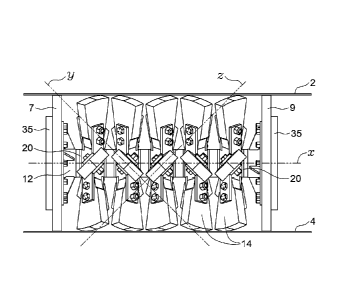
and typically involve inserting a pig into a conduit at a first point,
applying a motive
force to the pig, and traversing the pig through the conduit to clean the
inner surface
or wall of the conduit up to a second point, from which the conduit pig may be
retrieved
and removed. Conventional pigging componentry includes a device to launch the
apparatus into the conduit and a receiver system to retrieve it.
[0006] Pigs are normally configured to run approximately hundreds of kms
within
a conduit and can be constructed from a steel bullet-shaped body with metallic
and/or
rubber scraping members. For example, pipeline pigs are commonly designed to
have
a central body for supporting a plurality of abrasive scraping brushes,
plates, or bristles
that extend outward from the body and contact the interior surface of the
conduit wall.
As the pig moves through the conduit, the metallic brushes apply a mechanical
force
to rub off debris collected within the conduit¨for instance, by scraping or
brushing
debris built upon on the interior surface of the conduit.
[0007] Other conduit pigs are designed to support one or more fixed
(i.e., non-
rotating) disks extending outward from the central body. Such pigs are often
pressure
driven where fluids flowing through the pipeline act on the disks to push the
pig the
pipe. These disks preferably form a seal with the interior wall of the
conduit, amplifying
the motive force applied to the pig while pushing the debris downstream of as
the pig
moves through the conduit.
2
Date Recue/Date Received 2021-09-09
[0008] Although known conduit pigs and methodologies of use can remove
some
debris from the interior surface of a conduit, their effectiveness is limited.
Fixed
scraping members and disks often fail to agitate built-up debris with
sufficient force to
dislodge all debris. Fixed scraping members and disks are also configured to
agitate
debris from one direction of movement only, such that the conduit pig cannot
clean
the conduit in reverse or exert lateral force on the debris while the conduit
pig moves
forwards. This limited effectiveness necessitates more frequent pigging
operations
and results in an unavoidable buildup of immoveable debris over time, which
may
interfere with conduit operation. Such limitations are exacerbated by
operators looking
for more continuous pipeline processing to increase efficiencies and reduce
costs.
[0009] One known pipeline pig is disclosed in U.S. Patent Publication
No.
U52018/0363996 Al (the "996 Application"), the pig having fixed brush bristles
arranged secantially relative to the body of the pig, such bristles either
being arranged
in a clockwise orientation (resulting in rotation of the entire pig as it
transits the
.. conduit), or in both a clockwise and counter-clockwise orientation
(preventing rotation
of the pig). As a result, the fixed-bristle pig disclosed in the '996
Application provides
an example of known ineffective pipeline pigs that are only operative in one
direction
within the conduit and, although they may be configured to be rotatable, such
rotation
is unilateral and can result in the pig becoming lodged or stuck within the
conduit.
[0010] There is therefore a need for an improved conduit pig and methods of
use.
3
Date Recue/Date Received 2021-09-09
BRIEF DESCRIPTION OF THE DRAWINGS
[0011] Embodiments of the present apparatus and methodologies of use
will now
be described by way of an example embodiment with reference to the accompanied
simplified, diagrammatic, not-to-scale drawings 1 ¨ 13. In the drawings:
[0012] Figure 1 is a perspective view of an apparatus according to
embodiments
herein;
[0013] Figure 2A is a side view of the apparatus shown in FIG. 1, the
apparatus
positioned within the central bore of a fluid-carrying conduit, according to
embodiments;
[0014] Figure 2B is a side view of the apparatus shown in FIG. 2A, the
apparatus
being shown in motion within the central bore the fluid-carrying conduit,
according to
embodiments;
[0015] Figure 3 is cross-sectional side view of the apparatus shown in
FIG. 1,
according to embodiments;
[0016] Figure 4 is a front view of a first rotational element shown in
isolation, the
element arranged for rotation in a first direction (e.g., for rotation in a
counter-
clockwise direction) according to embodiments;
[0017] Figure 5 is a perspective view of the rotational element shown
in FIG. 4,
according to embodiments;
[0018] Figure 6 is a front view of a second rotational element shown in
isolation,
the element arranged for rotation in a second direction (e.g., for rotation in
a clockwise
direction), according to embodiments;
4
Date Recue/Date Received 2021-09-09
[0019] Figure 7 is a perspective view of the second rotational element
shown in
FIG. 6, according to embodiments;
[0020] Figure 8 shows an isolated side view of a connection means, the
connection means for securing at least one end disk to the present apparatus,
.. according to embodiments;
[0021] Figure 9A shows an inner perspective view of the connection
means shown
in FIG. 8, according to embodiments;
[0022] Figure 9B shows a side view of an inner bolt plate of the
connection means
shown in FIG. 8 and an end cap positioned relative thereto, according to
embodiments;
[0023] Figure 9C shows an outer perspective view of the inner bolt
plate shown in
FIG. 9B, according to embodiments;
[0024] Figure 10A shows an outer perspective view of the connection
means
shown in FIG. 8, according to embodiments;
[0025] Figure 10B shows a front view of the connection means shown in
FIG.8,
according to embodiments;
[0026] Figure 10C shows a perspective view of the end cap shown in FIG.
9B,
according to embodiments;
[0027] Figure 11A shows a front view of an alternative connection means
and end
cap, according to embodiments;
[0028] Figure 11B shows an outer perspective view of the alternative
connection
means shown in FIG. 11A, according to embodiments;
5
Date Recue/Date Received 2021-09-09
[0029] Figure 11C shows an outer perspective view of the alternative
end cap
shown in FIG. 11A, positioned relative to the inner bolt plate shown in FIG.
9C,
according to embodiments;
[0030] Figure 11D shows a side view of the alternative end cap shown in
FIG. 11A,
positioned relative to the inner bolt plate shown in FIG. 9C, according to
embodiments;
[0031] Figure 11E shows the alternative end cap shown in FIG. 11A,
according to
embodiments;
[0032] Figure 12 is a perspective view of an alternative embodiment of
the
apparatus shown in FIG. 1 according to embodiments, the alternative embodiment
of
the apparatus comprising a brushing element, according to embodiments; and
[0033] Figure 13 is an isometric side view of the alternative
embodiment of the
apparatus shown in FIG. 12, according to embodiments.
SUMMARY
[0034] According to embodiments, an apparatus for use in cleaning an
inner
sidewall of a fluid-carrying conduit is provided, the apparatus comprising a
tubular
shaft, having a first end and a second end, and one or more cleaning elements
rotatably mounted onto the shaft, each cleaning element forming a centrally
disposed
hub having at least one blade extending radially therefrom and frictionally
contacting
the sidewall of the conduit wherein, as the apparatus traverses through the
conduit,
the frictional contact between the at least one blade and the sidewall imparts
rotation
of the one or more cleaning elements about the shaft to clean the sidewall of
the
conduit.
6
Date Recue/Date Received 2021-09-09
[0035] In some embodiments, rotation of the cleaning elements may be in
a
clockwise or a counterclockwise direction relative to a longitudinal axis x of
the
apparatus. In some embodiments, the at least one blade extends perpendicularly
from
the hub at an angled or pitched orientation from a longitudinal axis x of the
apparatus.
For example, the at least one blade of a first cleaning element may be angled
in a first
orientation from the axis x to cause rotation of the cleaning element in a
clockwise
rotation, and the at least one blade of a second cleaning element may be
angled in a
second orientation from the axis x to cause rotation of the cleaning element
in a
counterclockwise direction. In some embodiments, the frictional contact of the
one or
more blades of the first and second cleaning elements with the sidewall of the
conduit
causes the first and second cleaning elements to rotate in opposite, counter-
rotating
directions.
[0036] In some embodiments, the apparatus further comprises at least
one first
and second end disks mounted on the shaft. The one or more cleaning elements
may
be positioned along the shaft in between the first and second end disks. In
some
embodiments, the at least one first end disk is mounted on the first end of
the shaft,
and the at least one second end disk is mounted on the second end of the
shaft. In
some embodiments, the first and second end disks have an outer diameter about
of
approximately greater than the inner diameter of the sidewall of the conduit.
[0037] In some embodiments, the apparatus may further comprise any number
of
brushing elements positioned along the shaft in between the first and second
end
disks and/or the one or more cleaning elements.
7
Date Recue/Date Received 2021-09-09
[0038] In some embodiments, the apparatus may further comprise any
number of
spacing elements positioned along the shaft in between the first and second
end disks,
the one or more cleaning elements, and/or the any number of brushing elements.
[0039] According to embodiments, methods of cleaning an inner sidewall
of a fluid-
carrying conduit are provided, the methods comprising providing an apparatus
for
cleaning the sidewall into the conduit, wherein the apparatus has a tubular
shaft,
having a first end and a second end and one or more cleaning elements
rotatably
mounted on the shaft, each cleaning element having at least one blade
extending
radially therefrom for frictionally contacting the sidewall of the conduit.
The apparatus
is positioned or 'launched' within the conduit at a first position where fluid
pressures
generated by fluids flowing through the conduit can impart an axial force on
the
apparatus causing it to move to a second position within the conduit, wherein
movement of the apparatus causes the one or more cleaning elements to
frictionally
engaged with the sidewall and rotate about the shaft and clean the sidewall.
[0040] In some embodiments, the one or more cleaning elements rotate in a
clockwise or a counterclockwise direction relative to a longitudinal axis x of
the
apparatus. In some embodiments, at least two of the one or more cleaning
elements
rotate about the shaft in opposite, counter-rotating directions. In some
embodiments,
the apparatus may travel within the conduit in either a forward or backward
direction
relative to a longitudinal axis x of the apparatus.
[0041] In some embodiments, the methods may include providing at least
one first
and second end disks positioned on the shaft for frictionally contacting the
sidewall of
8
Date Recue/Date Received 2021-09-09
the conduit. In some embodiments, the at least one first and second end disks
are
positioned at the first and the second end of the shaft, respectively.
[0042] In some embodiments, the methods may include providing any
number of
brushing elements positioned along the shaft in between the first and second
end
disks and/or the one or more cleaning elements.
[0043] In some embodiments, the methods may include providing any
number of
spacing elements positioned along the shaft in between the first and second
end disks,
the one or more cleaning elements, and/or the any number of brushing elements.
[0044] The above-mentioned and other features of the present apparatus
and
methodology will be best understood by reference to the following description
of
embodiments.
DETAILED DESCRIPTION OF VARIOUS EMBODIMENTS
[0045] The following description of embodiments is presented for
purposes of
illustration and description and is not intended to limit the scope of the
embodiments
to the forms disclosed herein. Consequently, variations and modifications
commensurate with the following teachings, and skill and knowledge of the
relevant
art, are within the scope of the presented embodiments. The various
embodiments
described herein are further intended to explain the best modes known of
practicing
the apparatus and to enable others skilled in the art to utilize the apparatus
in such or
other embodiments and with various modifications required by the particular
application(s) or use(s) of the presented embodiments. Reference will now be
made
to the accompanying Figures 1 ¨ 13, which assist in illustrating various
pertinent
features of the present apparatus and methodologies of use.
9
Date Recue/Date Received 2021-09-09
[0046] According to embodiments, an improved apparatus 10 and
methodologies
of use for cleaning debris and contaminants from fluid-carrying conduits are
provided.
Broadly, the present apparatus 10 may be configured for insertion or 'launch'
into any
fluid-carrying conduit 2, the conduit 2 being a tubular having an inner bore
forming a
generally circular cross-sectional sidewall 4 (e.g., see FIG. 2). The present
apparatus
serves to provide a simple, cost-effective tool having counter-rotating
cleaning
elements for enhanced removal of contaminants and debris from the sidewall 4
of the
conduit 2. For illustrative purposes, the present apparatus 10 will be
described for use
in cleaning a fluid-carrying pipeline in the oil and gas industry, however any
applicable
10 methods of use of the present apparatus 10 in any suitable fluid-
carrying conduit 2
known in the art are contemplated.
[0047] Having regard to FIG. 1, the present apparatus 10 may comprise a
centrally
disposed shaft 12 extending between a first terminal end 6 and a second
terminal end
8, and along a longitudinal axis x of the apparatus (e.g., see FIG. 2A). Shaft
12 may
comprise a tubular configuration and be manufactured from any appropriate
resilient
material, such as carbon steel, stainless steel, brass, copper, or rigid
polymers.
[0048] In some embodiments, shaft 12 may be configured to receive one
more
cleaning elements or 'propellers' 14 slidably mounted onto shaft 12, the
elements 14
serving to contact and clean the sidewall 4 of the conduit 2 as the apparatus
10 moves
through the conduit 2. Cleaning elements 14 may form a centrally disposed
aperture
22 (e.g., see FIG.4) for slidably receiving shaft 12 therethrough. For
example, during
assembly, each one or more cleaning element 14 may be mounted in series onto
shaft
Date Recue/Date Received 2021-09-09
12 by sliding first or second terminal end 6,8 through each aperture 22, and
then
positioning each element 14 in place longitudinally along the shaft 12.
[0049] Shaft 12 may be configured to receive at least one first end
disk 7 and at
least one second end disk 9, the ends disks 7,9 mounted onto shaft 12 at or
near
terminal ends 6,8, respectively. As will be described, cleaning elements 14
may be
positioned along shaft 12 between terminal ends 6,8 and secured onto shaft 12
by
end disks 7,9.
[0050] Having regard to FIG. 2A, cleaning elements 14 are rotatably
positioned
about shaft 12, i.e., each one or more cleaning element 14 may freely rotate
thereabout. In some embodiments, each one or more cleaning element 14 may
comprise a central hub 20 rotatable about shaft 12. Hub 20 may form aperture
22
therethrough (e.g., see FIGS. 5 and 7) and may further be configured to
support at
least one blade 24 mounted thereto and extending radially therefrom.
[0051] Having regard to FIG. 2B, blades 24 may be manufactured from a
malleable, resistant, and resilient material, and configured such that, at a
distal end,
each blade 24 frictionally engages or contacts the inner sidewall 4 of conduit
2. As
apparatus 10 moves through conduit 2 (see arrow to denote direction of
travel), blades
24 may flex or deform in shape in response to the frictional drag along
sidewall 4. In
some embodiments, blades 24 may be manufactured from any malleable, resistant,
and resilient material capable of resisting damage caused by scraping against
sidewall
4, as well as damage caused by temperature, pressure, chemical, and electrical
conditions within the conduit 2. Such materials may include wear-resistant
11
Date Recue/Date Received 2021-09-09
polyurethane, as may be commercially available (e.g., Apache Pipeline
Products,
Canada).
[0052] In some embodiments, having regard to FIGS. 4 ¨ 7, hub 20 may
support
a plurality of blades 24, and preferably at least five blades 24. Blades 24
may be
manufactured to be integral with hub 20, or blades 24 may be distinct elements
securely connected thereto. Where blades 24 are distinct elements, at least a
portion
of a proximal or 'root' end of each blade 24 may be secured to hub 20 using
any
appropriate mechanical connection means, such as by one or more nuts 21 bolted
through bolt plates 23 (e.g., see FIGS. 5 and 7, where bolt plates 23 may
comprise
two opposed flanges welded to hub 20).
[0053] In some embodiments, as above, blades 24 may be configured such
that a
distal or 'tip' end of each blade 24 contacts the inner surface of sidewall 4
of conduit
2. In some embodiments, the distal tip of each blade 24 may have a width that
is
greater than the depth of the distal tip. In such embodiments, the distal tip
may be
shaped (e.g., rounded or curved) across its width to generally conform to the
curvature
of sidewall 4 and maximize the frictional contact therebetween. As should be
appreciated, such contact between each blade 24 and sidewall 4 serves to
agitate,
dislodge, and clean debris within conduit 2. Moreover, as will be described,
such
contact between each blade 24 and sidewall 4 serves to cause rotation of each
cleaning element 14 and hub 20 about shaft 12, such rotation advantageously
being
in either clockwise or counter-clockwise direction. For example, having
further regard
to FIG. 2A, the at least one blades 24 may be specifically orientated or
angled relative
to the longitudinal axis x to impart rotation of element 14 about shaft 12 as
apparatus
12
Date Recue/Date Received 2021-09-09
travels through conduit 2. That is, as apparatus 10 moves either a forward or
backward direction within the conduit 2, the at least one blades 24 contact
the sidewall
4 of the conduit 2 and, because of the specific orientation of each distal end
relative
to the sidewall and the frictional force applied thereto, cause the entire
element 14 (via
5 hub 20) to rotate about shaft 12 in either a clockwise or counter
clockwise direction.
[0054] For example, in some embodiments, some of the at least one blade
24 may
be mounted substantially perpendicularly onto hub 20, extending radially
therefrom,
and at a first pitched angle with respect to the longitudinal axis x of the
apparatus 10
(e.g., depicted as z, see FIG. 2A). In this example, each blade 24 may be
faced such
10 that contact of the distal tip of blade 24 with sidewall 4 imparts
rotation of the blade 24
in a clockwise direction about the shaft 12 (i.e., about longitudinal axis x
when viewed
from first terminal end 6). As would be appreciated, the direction of rotation
may be
determined by the vector sum, or resultant, of forces applied to the face of
each blade
24, namely drag forces caused by the friction between the distal tip of blade
24 and
sidewall 4 and resisting forces caused by the internal structure of blade 24.
Drag
forces oppose the movement of apparatus 10 through conduit 2 and are parallel
to
longitudinal axis x (i.e., vectored right to left). Resisting forces oppose
deflection of
blade 24 and are perpendicular to pitched angle (i.e., vectored top left to
bottom right),
and the resultant drag forces and resisting forces cause blade 24 to rotate
(i.e.,
vectored top to bottom). It is contemplated that the at least one blade 24 may
be
positioned on hub 20 at any angle appropriate to cause rotation of hub 20
(i.e., any
blade twist relative to the longitudinal axis x) or, for example, such that
the pitch angle
13
Date Recue/Date Received 2021-09-09
of the at least one blade 24 ranges from approximately 10 ¨ 900, and
preferably about
450 (e.g., depicted as axis z).
[0055] Alternatively, in some embodiments, some of the at least one
blade 24 may
be mounted substantially perpendicularly onto hub 20, extending radially
therefrom,
and at a second pitched angle with respect to the longitudinal axis x of the
apparatus
(e.g., depicted as y, see FIG.2A). In this example, each blade 24 may be faced
such that contact of the distal tip of blade 24 with sidewall 4 imparts
rotation of the
blades 24 in a counter clockwise direction about the shaft 12 (i.e., or an
direction
opposite axis z described above about longitudinal axis x when viewed from
first
10 terminal end 6). It is contemplated that the at least one blade 24 may
be positioned
on hub 20 at any angle appropriate to cause rotation of hub 20 (i.e., any
blade twist
relative to the longitudinal axis x) or, for example, such that the pitch
angle of the at
least one blade 24 ranges from approximately 91 ¨ 180 , and preferably 135
(e.g.,
depicted as axis y).
[0056] In operation, having regard to FIG. 2B, as the apparatus 10 travels
through
conduit 2 in either forward or backwards direction along longitudinal axis x,
at least
one blade 24 frictionally contacts and scrapes along sidewall 4, causing
rotational
movement of blades 24 (and correspondingly element 14) about shaft 12. In
combination, each of the frictional engagement of the blades 24 with the
sidewall 4
and the rotation of elements 14 and blades 24 serve as a mechanical propeller
about
central hub 20 for enhanced cleaning of conduit 2.
[0057] As would be appreciated, blades 24 may be sized, shaped, and
orientated
so as to trace opposed helical spirals along sidewall 4 of conduit 2 as
apparatus 10
14
Date Recue/Date Received 2021-09-09
moves through conduit 2 (e.g., akin to continuous bi-directional screws)
capable of
achieving an enhanced contra-rotational cleaning effect, reducing the overall
number
of passes needed and minimizing both the time and the cost to effectively
clean the
conduit 2. Moreover, the enhanced contra-rotational cleaning effect also
eliminates
the need for the entire apparatus 10 to rotate, which may be advantageous if,
for
example, apparatus 10 is connected to external componentry (described below).
[0058] Having regard to FIG. 3, in some embodiments, at least one
tubular spacing
element 15 may be used to maintain a predetermined distance between cleaning
elements 14 along shaft 12. Spacing elements 15 may be any size and
configuration
as desired, and may be manufactured to withstand the potentially harsh
environment
within conduit 2 including from carbon steel, stainless steel, copper, rigid
polymers,
and preferably brass, or the like.
[0059] In some embodiments, spacing elements 15 may be substantially
cylindrical in shape such that spacing elements 15 may be slidably mounted on
to
shaft 12 during assembly, as desired. As would be appreciated, each one or
more
spacing element 15 serves to maintain a pre-determined distance between
cleaning
elements 14 along shaft 12, to provide bearings between each element 14, and
to
maintain a pre-determined distance between elements 14 and at least one
brushing
element 16 along shaft 12 (described below). For example, when an optional
brushing
element 16 is used, at least one spacing element 15 may be slidably mounted
onto
shaft 12 in between each cleaning element 14 and the one or more brushing
elements
16.
Date Recue/Date Received 2021-09-09
[0060] As above, in some embodiments, apparatus 10 comprises a shaft 12
having first and second terminal ends 6,8, for mounting first and second end
disks 7,9,
respectively. Returning to FIG. 3, each end disk, 7,9 may be sized and shaped
to
generally correspond with or exceed the inner diameter of sidewall 4, such
that disks
7,9 sealingly engage therewith as the apparatus 10 moves through the conduit
2. In
this regard, disks 7,9 encompass the entire diameter of the conduit 2,
providing a
surface for receiving hydraulic pressures generated by fluids flowing through
conduit
2, such pressures acting upon disks 7,9 to actuate apparatus 10 through
conduit 2.
Advantageously, fluid pressures may be imposed on either disk 7,9 to move
apparatus
.. 10 in either a forward or backwards direction through conduit 2.
[0061] In some embodiments, each end disk 7,9 may be substantially
circular in
cross section and may form a centrally disposed aperture for slidably
receiving shaft
12 therethrough. For example, during assembly, each end disk 7,9 may be
mounted
onto shaft 12 by sliding first or second terminal end 6,8, respectively,
through each
disk 7,9 and then positioning each disk 7,9 in place longitudinally along
shaft 12.
Advantageously, where desired, one or both disks 7,9 may be easily removed
from
apparatus 10 for maintenance, cleaning, and replacement, or to accommodate
different conduits 2 of varying sizes and/or fluid capacities.
[0062] In some embodiments, disks 7,9 may be configured such that the
circumference of each disk 7,9 frictionally engages with or contacts the inner
surface
of sidewall 4. Disks 7,9 may comprise an outer diameter that is equal to or
greater
than the interior diameter of the conduit 2. Disks 7,9 may be manufactured
from
flexible or malleable material so as to permit insertion of apparatus 10 into
conduit 2
16
Date Recue/Date Received 2021-09-09
notwithstanding that disks 7,9 may comprise a slightly greater outer diameter
relative
to the inner diameter of the conduit 2. Disks 7,9, may serve to stabilize
and/or
centralize apparatus 10 within conduit 2 and may provide further cleaning
elements
for additional cleaning without inhibiting travel of the apparatus 10 though
conduit 2.
By way of example, disks 7,9 may have an outer diameter approximately 0",
1/4", 1/2",
or %" greater than the interior diameter of the conduit 2, or otherwise
desired and
based on the internal diameter of conduit 2.
[0063] In some embodiments, disks 7,9 may be manufactured from any
malleable
and resilient material capable of resisting damage caused by scraping against
sidewall
4, as well as damage caused by temperature, pressure, chemical, and electrical
conditions within the conduit 2. Disks 7,9 may also be formed of any material
that is
suitable for sealingly engaging with sidewall 4 and further capable to
withstand fluid
pressures within conduit 2. In this regard, disks 7,9 are operative to receive
and
respond to fluid pressure transmitted thereto in order to move apparatus 10
within
conduit 2. Such materials may include wear-resistant polyurethane, as may be
commercially available (e.g., Apache Pipeline Products, Canada).
[0064] As would be appreciated, the additional frictional contact
between disks 7,9
and sidewall 4 enhances the agitation of the debris and contaminants within
conduit
2, compounding the cleaning effect provided by blades 24 and optimizing
apparatus
10 efficiency.
[0065] In some embodiments, disks 7,9 may be releasably secured onto
shaft 12
by one or more mechanical connection means, said connection means being any
suitable means known in the art. For example, having regard to FIG. 8 (only
end disk
17
Date Recue/Date Received 2021-09-09
9 is shown for illustration purposes), end disk 9 may form at least one bolt
hole for
receiving one or more nuts 31 bolted through opposed, corresponding bolt
plates
33,35.
[0066] More specifically, corresponding bolt plates may comprise an
inner or
interior bolt plate 33 for receiving at least one end disk 9 mounted thereon
(FIGS. 9A
¨ 9C, only end disk 9 shown for illustration purposes) and an outer or
exterior bolt
plate 35 (FIGS. 10A ¨ 10B, only disk 9 shown for illustration purposes).
During
assembly, inner plate 33 may be slidably mounted onto shaft 12 first followed
by outer
bolt plate 35, the plates 33,35 sandwiching disk 9 securely therebetween. In
some
embodiments, bolt plates 33,35 may be manufactured from carbon steel,
stainless
steel, brass, copper, or rigid polymers. Advantageously, exterior bolt plates
35 may
also serve as 'bumpers' or 'stops', preventing damage to apparatus 10 where it
may
inadvertently contact componentry or other obstructions within conduit 2
(e.g., valves,
elbows, joints, or the like).
[0067] Bolt plate 33 may be releasably connected to shaft 12 for ease of
assembly
and disassembly. It should be appreciated that any suitable means for
releasably
securing end disks 7,9 onto shaft 12 are contemplated, and that the presently
described connection means are only provided as one example. For example, bolt
plate 33 may be secured to shaft 12 via at least one quick-release mechanism,
or
such other applicable securing means as known in the art.
[0068] For example, in some embodiments, inner bolt plate 33 may form
at least
one centrally disposed cylindrical portion 36 extending therefrom, said
portion 36
forming corresponding pin holes for receiving quick-release pin 37 (e.g., see
FIG. 9C).
18
Date Recue/Date Received 2021-09-09
In this regard, pin 37 may be easily inserted through bolt plate 33 and shaft
12 during
assembly, and then removed therefrom during disassembly of apparatus 10.
[0069] Having regard to FIG. 10C, connection means may further comprise
an end
cap 39 slidingly received within central bore of shaft 12, the end cap 39 also
comprising pin holes for receiving quick-release pin 37 and for sealingly off
the bore
of shaft 12. In some embodiments, end cap 39 may comprise an outer flange with
a
diameter that is approximately equal to the outer diameter of cylindrical
portion 36 of
inner bolt plate 33 and/or the outer diameter of shaft 12 of apparatus 10. In
some
embodiments, end cap 39 may be manufactured from carbon steel, stainless
steel,
brass, copper, or rigid polymers.
[0070] Having regard to FIGS. 11A ¨ 11C, end cap 39 may comprise an
outer
flange with a diameter that is greater than the diameter cylindrical portion
36 of inner
bolt plate 33 and/or the outer diameter of shaft 12 of apparatus 10. In such
embodiments, the outer flange of end cap 39 may comprise a connection means
for
connecting apparatus 10 to external componentry within conduit 2 (not shown),
such
as apparatus location transmitters and the like. For example, the connection
means
may include bolt holes to receive bolts extending from external componentry.
Advantageously, the bolt holes may correspond with various bolt configurations
that
are standard in the industry, allowing for convenient connection of apparatus
10 to
external componentry. It will be appreciated that other connection means are
known.
[0071] Having regard to FIGS. 12 and 13, in some embodiments, apparatus
10
may optionally comprise at least one brushing element 16 positioned along
shaft 12
in between first and second end disks 7,9 for further enhancing cleaning of
conduit 2.
19
Date Recue/Date Received 2021-09-09
In some embodiments, brushing element 16 may form a centrally disposed
aperture
for receiving either first or second end 6,8 of shaft 12 therethrough, and
such that
brushing element 16 may freely rotate about shaft 12 relative to axis x or,
alternatively,
be fixed in position on shaft 12. Brushing element 16 may be positioned along
shaft
12 such that one or more cleaning elements 14 are positioned between brushing
element 16 and each first and second end disk 7,9. Without limitation, in some
embodiments, brushing element 16 may be centrally disposed along shaft 12,
encircling shaft 12 in between end disks 7,9. Brushing element 16 may be
manufactured to withstand the potentially harsh environment within conduit 2
such as
carbon steel, stainless steel, brass, copper, rigid polymers, or the like
(e.g. Apache
Pipeline Products, Canada).
[0072] As shown in FIG. 12, the at least one brushing element 16 may
comprise a
plurality of rigid bristles 17. Bristles 17 may be radially disposed about
brushing
element 16 and of sufficient length such that, as apparatus 10 moves through
conduit
.. 2, bristles 17 frictionally engage with or contact inner sidewall 4 of
conduit 2, scraping
the debris and contaminants therefrom. Bristles 17 may be manufactured to as
to
provide approximately 360 contact with the inner sidewall 4. Bristles 17 may
be
manufactured to withstand the potentially harsh environment within conduit 2,
such
tempered steel wires (Apache Pipeline Products, Canada). As above, it is
contemplated that end disks 6,7, brushing element 16, and/or bristles 17 may
be
manufactured using any appropriate corrosion-resistant materials known in the
art.
[0073] During pipeline 'pigging' operations, the present apparatus 10
for cleaning
an inner sidewall 4 of a fluid-carrying conduit 2 may first be inserted into
the conduit 2
Date Recue/Date Received 2021-09-09
and positioned such that either first or second terminal end 6,7 faces the
direction of
fluid flow and/or movement or the apparatus 10 through the conduit 2. That is,
apparatus 10 may be capable of traveling bi-directionally, or operative in
either a
forward or backwards direction, within the conduit 2, regardless of the
direction of fluid
flow or movement of the apparatus 10 along the longitudinal axis x.
[0074] Once in position, hydraulic pressures from fluids pumping
through conduit
2 act upon end disk 7,9 to impart axial movement of apparatus 10 along the
conduit
2. As apparatus 10 travels through conduit 2, at least one blade 24 from the
one or
more cleaning elements 14 frictionally engages sidewall 4, scraping the wall
and
.. removing debris therefrom. As above, due to the specific positioning of
blades 24,
movement of apparatus 10 along conduit 2 causes rotation of the one or more
cleaning
elements 14, said rotation being in either the clockwise or counter-clockwise
direction
depending upon the orientation of blades 24.
[0075] Advantageously, as apparatus 10 travels through conduit, end
disks 7,9
also make scraping contact with the inner sidewall 4 of conduit, enhancing the
cleaning of debris therefrom. Optionally, where desired, bristles 17 of
brushing
element 16 can also be used to further enhance cleaning. When 'pigging'
operations
are complete, apparatus 10 may be retrieved and removed from conduit 2.
[0076] More specifically, according to embodiments, methods of cleaning
an inner
sidewall of a fluid-carrying conduit are provided. In some embodiments, the
method
comprises provided an apparatus for cleaning the sidewall, positioning or
'launching'
the apparatus within the conduit at a first position, allowing hydraulic
pressures from
fluid flowing through the conduit the conduit to impart axial forces on the
apparatus to
21
Date Recue/Date Received 2021-09-09
move the apparatus to a second position within the conduit, wherein movement
of the
apparatus causes one or more cleaning elements of the apparatus to
frictionally
engage with the sidewall to clean the sidewall.
[0077] In some embodiments, the apparatus for use in cleaning the inner
sidewall
may comprise a tubular shaft 12, having a first end and a second end 7,8, one
or more
cleaning elements 14, each cleaning element 14 rotatably mounted onto the
shaft 12
between the first and second end 7,8, and each cleaning element 14 having at
least
one blade 24 extending radially therefrom for frictionally contacting the
sidewall 4 of
the conduit 2.
[0078] The previous description of the embodiments disclosed herein is
provided
to enable any person skilled in the art to make or use the presently disclosed
invention.
Various modifications to those embodiments will be readily apparent to those
skilled
in the art, and the generic principles defined herein may be applied to other
embodiments without departing from the scope of the claims. Thus, the
presently
disclosed invention is not intended to be limited to the embodiments disclosed
herein,
but is to be accorded the full scope consistent with the claims, wherein
reference to
an element in the singular, such as by use of the articles "a" or "an" is not
intended to
mean "one and only one" unless specifically so stated, but rather is intended
to mean
"one or more." All structural and functional equivalents to the elements of
the
embodiments disclosed herein that are known or later come to be known to those
of
ordinary skill in the art are intended to be encompassed by the elements of
the claims.
Moreover, nothing disclosed herein is intended to be dedicated to the public
regardless of whether such disclosure is explicitly recited in the claims.
22
Date Recue/Date Received 2021-09-09