Note: Descriptions are shown in the official language in which they were submitted.
CA 03130445 2021-08-16
1/47
[DESCRIPTION]
[Invention Title]
VACUUM HEAT-INSULATION DEVICE FOR LOW-TEMPERATURE TANK
[Technical Field]
[0001] The present invention relates to a device for vacuum-
insulating a lower-temperature tank, and more particularly,
to a device capable of vacuum-insulating a lower
temperature tank for storing and transporting a liquefied
gas in an ultra-low-temperature state.
[0002]
[Background Art]
glom In general, a liquefied natural gas (LNG) refers to a
colorless and transparent ultra-low-temperature liquid
whose volume is reduced to 1/600 by cooling a natural gas
containing methane as a main component to -162 C. As such
a liquefied natural gas appears as an energy resource, in
order to use such a gas as energy, an efficient
transportation method that may transport the liquefied
natural gas in large quantities from a production base to a
receiving site of a demand site has been reviewed. As a
result, a liquefied natural gas carrier for sea
transportation of the liquefied natural gas has appeared.
[0004]The liquefied natural gas carrier as described above
should be provided with a low-temperature tank capable of
storing the liquefied natural gas liquefied in an ultra-low
Date Recue/Date Received 2021-08-16
CA 03130445 2021-08-16
2/47
temperature state for storage and transportation, and in
order to store the liquefied natural gas having a medium
atmospheric pressure higher than atmospheric pressure and a
boiling temperature of -160 C, such a low-temperature tank
should be made of materials (aluminum alloy, stainless
steel, 35% nickel steel, etc.) that may withstand an ultra-
low-temperature, and requires a design that may cope with
thermal stress and thermal contraction, and installation of
an insulation structure that may prevent heat intrusion.
[0005]Here, the low-temperature tank applied to the
liquefied natural gas carrier may be classified into a
membrane type and a self-supporting type according to a
structure thereof. The membrane type tank is made in such
a way that a hull supports a pressure generated inside the
tank by using a corrugated membrane sheet made of stainless
steel on an inner surface of the tank in which the
liquefied gas is stored to enable thermal contraction in
response to thermal deformation caused by the liquefied gas
and forming a heat-insulation material layer surrounding an
outer surface to support the membrane sheet and a secondary
barrier supported on the hull of the carrier, as disclosed
in Korean Patent Laid-Open Publication No. 10-2017-0116584
(SEALED TANK WITH CORRUGATED SEALING MEMBRANES published on
October 19, 2017).
[0006] In this case, conventionally, in order to prevent a
Date Recue/Date Received 2021-08-16
CA 03130445 2021-08-16
3/47
moisture remaining in the heat-insulation material layer
from being cooled to deteriorate a performance of the heat-
insulation material, the tank is filled with dry air having
a dew point of -50 to -60 C, but in the case of liquefied
hydrogen (LH2), which is liquefied and has a boiling
temperature of -250 C, oxygen and nitrogen of the dry air
filled therein are liquefied and condensed near a surface
of a liquefied hydrogen tank to significantly degrade the
performance of the insulation, thereby causing problems
that a performance failure of the entire heat-insulation
layer is caused, and long-term reliability of stability of
the tank is questionable.
[0007]
[Disclosure]
[Technical Problem]
[0008]An object of the present invention is to provide a
vacuum heat-insulation device for a large low-temperature
tank having high thermal insulation and vacuum stability by
using a heat-insulation material maintained in a vacuum at
all times so as to store an ultra-low-temperature liquefied
gas such as liquid nitrogen (LN2) or liquid hydrogen (LH2).
[0009]
[Technical Solution]
[0010] According to a vacuum heat-insulation device for a
low-temperature tank of the present invention, it is
Date Recue/Date Received 2021-08-16
CA 03130445 2021-08-16
4,417
possible to provide a vacuum heat-insulation device for a
low-temperature tank capable of storing an ultra-low-
temperature fluid such as liquid hydrogen (LH2) or liquid
nitrogen (LN2) by maintaining a low-temperature heat-
insulation layer in a vacuum state.
[0011]Further, it is possible to provide a vacuum heat-
insulation device for a low-temperature tank that supports
a pressure of the ultra-low-temperature fluid stored
therein by the low-temperature tank itself, and may cope
with a thermal contraction of the low-temperature tank by a
temperature of the ultra-low-temperature fluid by
configuring a portion of a vacuum jacket to have a flexible
structure that may be contracted according to the
contraction of the low-temperature tank or the low-
temperature heat-insulation layer.
[0012]
[Advantageous Effects]
[0013] According to the present invention having the above-
mentioned configurations, it is possible to provide the
vacuum jacket that may maintain the low-temperature heat-
insulation layer surrounding the outer shell of the low-
temperature tank in the vacuum state at all times to
maintain higher insulation efficiency, thereby securing
long-term reliability, and may support a pressure of the
ultra-low-temperature fluid stored therein by the low-
Date Recue/Date Received 2021-08-16
CA 03130445 2021-08-16
5,47
temperature tank itself and may cope with the thermal
contraction of the low-temperature tank by the temperature
of the ultra-low-temperature fluid by a portion of the
vacuum jacket having a flexible structure that may be
contracted according to the contraction of the low-
temperature tank or the low-temperature heat-insulation
layer, thereby manufacturing the large tank having long-
term high reliability.
[0014]
[Description of Drawings]
[0015]FIG. 1 is a perspective view illustrating a vacuum
heat-insulation device according to an embodiment of the
present invention.
[0016]FIG. 2 is a cross-sectional view illustrating a
vacuum heat-insulation device according to a first
embodiment of the present invention.
[0017]FIGS. 3 to 5 are cross-sectional views illustrating
various modified examples of a deformable joint portion
according to the first embodiment of the present invention.
[0018]FIG. 6 is a perspective view illustrating a vacuum
heat-insulation device according to a second embodiment of
the present invention.
[0019]FIGS. 7 and 8 are cross-sectional views illustrating
various modified examples of a low-temperature heat-
insulation layer according to an embodiment of the present
Date Recue/Date Received 2021-08-16
CA 03130445 2021-08-16
6,47
invention.
[0020] FIG. 9 is a view illustrating various modified
examples of an internal discharge space taken along section
AA' in FIG. 6.
[0021] FIG. 10 is a cross-sectional view illustrating a
vacuum heat-insulation device according to a third
embodiment of the present invention.
[0022]FIGS. 11 to 15 are cross-sectional views illustrating
various modified examples of the vacuum heat-insulation
device according to the third embodiment of the present
invention.
[0023]FIG. 16 is a cross-sectional view illustrating a
vacuum jacket having a double structure according to an
embodiment of the present invention.
[0024]FIGS. 17 to 21 are cross-sectional views illustrating
a vacuum heat-insulation device according to a fourth
embodiment of the present invention.
[0025]
[Best Mode]
[0026] In one general aspect, a vacuum heat-insulation
device for a low-temperature tank includes: a low-
temperature tank having a storage space for accommodating
an ultra-low-temperature fluid therein; a low-temperature
heat-insulation layer provided to surround an outer shell
of the low-temperature tank; and a vacuum jacket having an
Date Recue/Date Received 2021-08-16
CA 03130445 2021-08-16
/L1:7
internal space maintained in a vacuum state and sealed to
surround an outer surface of the low-temperature heat-
insulation layer to maintain airtightness with the outside,
wherein the vacuum jacket has a flexible structure in which
at least a portion thereof is contracted or expanded.
[0027]The vacuum jacket may include a plurality of smooth
portions surrounding the outer surface of the low-
temperature heat-insulation layer and made of flat plates
spaced apart from each other by a predetermined distance,
and a deformable joint portion formed between the plurality
of smooth portions and having the flexible structure.
[0028]The deformable joint portion may connect the
plurality of smooth portions, and may be formed of a
polymer elastic body that is stretchable in response to a
deformation of the internal space of the vacuum jacket.
[0029]The polymer elastic body may be interposed between
the plurality of smooth portions and may be bonded to outer
side ends of the plurality of smooth portions in a width
direction thereof.
[0030] The plurality of smooth portions may be provided to
overlap with at least one adjacent smooth portion in a
thickness direction, and respond to the contraction or
expansion of the internal space while being slid when the
internal space is deformed, and the polymer elastic body
may be provided on upper surfaces of portions overlapped
Date Recue/Date Received 2021-08-16
CA 03130445 2021-08-16
8,47
with the plurality of smooth portions to maintain the
airtightness of the vacuum jacket and may be contracted or
expanded in response to the deformation of the smooth
portions.
[0031] The low-temperature heat-insulation layer may be
provided in plural, and the plurality of low-temperature
heat-insulation layers may be provided to be spaced apart
from each other to form an internal discharge space forming
a flow path for forming a vacuum between the plurality of
low-temperature heat-insulation layers that are adjacent to
each other.
[0032]The plurality of low-temperature heat-insulation
layers may be provided to form a multiple layer in the
thickness direction, and may be fixed to at least one of
the outer shell of the low-temperature tank, the vacuum
jacket, or the adjacent low-temperature heat-insulation
layer using a fixing bolt to be spaced apart from each
other by a predetermined distance.
[0033]The vacuum heat-insulation device may further include
a discharge pipe provided in the internal discharge space
and having a suction hole that is formed on an outer
circumferential surface and communicates with the internal
space of the vacuum jacket.
[0034]The deformable joint portion may be integrally formed
with the plurality of smooth portions, and form a concave-
Date Recue/Date Received 2021-08-16
CA 03130445 2021-08-16
9/47
convex portion curved outwardly in the thickness direction,
and the concave-convex portion may be deformed according to
the contraction or expansion of the internal space of the
vacuum jacket.
[0035]The deformable joint portion may be configured to
form an internal discharge space forming a flow path for
forming a vacuum inside the concave-convex portion curved
outwardly in the thickness direction.
[0036]The vacuum jacket may be integrally formed by welding
the plurality of smooth portions, and a welding line formed
on the outer surface of the vacuum jacket may be provided
in the internal space of the vacuum jacket and may be
formed at a position coincident with the internal discharge
space.
[0037]The vacuum jacket may be integrally formed by welding
the plurality of smooth portions, and the vacuum heat-
insulation device may further include a high-temperature
heat-insulation material provided inside the welding line
formed on the outer surface of the vacuum jacket to prevent
thermal deformation of the low-temperature heat-insulation
layer near the welding line.
[0038]The vacuum jacket may include a first vacuum jacket
surrounding the outer surface of the low-temperature heat-
insulation layer and a second vacuum jacket provided to
surround an outer surface of the first vacuum jacket, and
Date Recue/Date Received 2021-08-16
CA 03130445 2021-08-16
10/47
the vacuum heat-insulation device may further include a
spacer interposed between the first vacuum jacket and the
second vacuum jacket to separate the first vacuum jacket
and the second vacuum jacket from each other by a
predetermined distance.
[0039] The vacuum jacket may include a flexible portion
surrounding the outer surface of the low-temperature heat-
insulation layer and having the flexible structure, and a
robust portion in which at least a portion of the vacuum
jacket having a robust structure supports the vacuum heat-
insulation device.
[0040] The low-temperature tank may be made of a polyhedron,
the flexible portion may be formed to surround the outer
surface of the low-temperature heat-insulation layer
forming a plane of the vacuum jacket, and the robust
portion may be formed to surround the outer surface of the
low-temperature heat-insulation layer forming a corner of
the vacuum jacket.
[0041] The vacuum jacket may be configured to form an
internal discharge space forming a flow path for forming a
vacuum inside the robust portion.
[0042] The robust portion may be formed to surround the
outer surface of the low-temperature heat-insulation layer
constituting a lower portion of the vacuum jacket, and
support a bottom surface of the vacuum heat-insulation
Date Recue/Date Received 2021-08-16
CA 03130445 2021-08-16
11/47
device.
[0043]The vacuum heat-insulation device may further include
a tank support body formed to support the low-temperature
tank in a floating state, and separate a lower end of the
vacuum jacket from the ground by a predetermined distance.
[0044]The tank support body may include: a tank hanger
connected to the upper surface of the low-temperature tank,
an upper support body that supports the tank hanger and
forms a portion of the vacuum jacket, and a side support
body that extends upwardly such that the lower end of the
vacuum jacket is spaced apart from the ground to support
the upper support body.
[0045]The tank support body may include: a tank hanger
connected to a side surface of the low-temperature tank,
and a side support body that forms a portion of the vacuum
jacket and extends upwardly so that the lower end of the
vacuum jacket is spaced apart from the ground to support
the tank hanger.
[0046]
[0047]Since the present invention may be variously modified
and have several embodiments, specific embodiments will be
illustrated in the accompanying drawings and be described
in detail. However, it is to be understood that the
present invention is not limited to a specific embodiment,
but includes all modifications, equivalents, and
Date Recue/Date Received 2021-08-16
CA 03130445 2021-08-16
12/47
substitutions without departing from the scope and spirit
of the present invention.
[0048] It is to be understood that when one element is
referred to as being "coupled to" or "connected to" another
element, it may be directly coupled to or directly
connected to another element or be coupled to or connected
to another element while having the other element
interposed therebetween.
[0049] Unless otherwise defined, all terms, including
technical or scientific terms, used herein have the same
meaning as commonly understood by one of ordinary skill in
the art to which the present invention belongs.
[0050] It should be interpreted that terms defined by a
generally used dictionary are identical with the meanings
within the context of the related art, and they should not
be ideally or excessively formally interpreted unless the
context clearly dictates otherwise.
[0051] Hereinafter, a technical spirit of the present
invention will be described in more detail with reference
to the accompanying drawings.
[0082] The accompanying drawings are only examples shown to
describe the technical spirit of the present invention in
more detail, and therefore, the technical spirit of the
present invention is not limited to the form of the
accompanying drawings.
Date Recue/Date Received 2021-08-16
CA 03130445 2021-08-16
13/47
[0053]
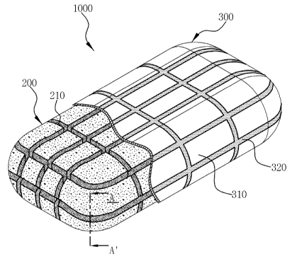
(0054] FIG. 1 is a perspective view illustrating a vacuum
heat-insulation device according to an embodiment of the
present invention and FIG. 2 is a cross-sectional view
illustrating a vacuum heat-insulation device according to a
first embodiment of the present invention. Referring to
FIGS. 1 and 2, a vacuum heat-insulation device 1000
according to an embodiment of the present invention may
include a low-temperature tank 100 having a storage space
for accommodating an ultra-low-temperature fluid therein, a
low-temperature heat-insulation layer 200 provided to
surround an outer shell 110 of the low-temperature tank, a
vacuum jacket 300 that is formed to surround an outer
surface of the low-temperature heat-insulation layer 200
and maintains airtightness with the outside, and a vacuum
pump 410 connected to an internal space of the vacuum
jacket 300 to maintain the low-temperature heat-insulation
layer 200 interposed in the inner space in a vacuum state.
[0055] In this case, the vacuum heat-insulation device 1000
may maintain the internal space of the vacuum jacket 300
provided with the low-temperature heat-insulation layer 200
at a constant vacuum pressure to suck a gas or moisture
remaining therein and discharge the gas or moisture to the
outside, thereby further increasing an insulation
performance of the low-temperature heat-insulation layer
Date Recue/Date Received 2021-08-16
CA 03130445 2021-08-16
14/47
200. Here, when the pressure of the low-temperature heat-
insulation layer 200 is maintained in a vacuum, the low-
temperature heat-insulation layer 200 receives a
compression of 1 atmosphere, and it is necessary to use a
material having sufficient compressive strength so that
compressibility is not deteriorated. Preferably, it is
possible to secure sufficient insulation performance and
compressive strength by using a reinforced polymer
(reinforced poly urethane foam: R-PUF). In addition, the
applicant confirmed that when the pressure of the low-
temperature heat-insulation layer 200 was maintained in the
vacuum state, thermal conductivity of the low-temperature
heat-insulation layer 200 is reduced to less than half that
of the low-temperature heat-insulation layer placed under a
pressure of 100 KPa. Here, the operation of the vacuum
pump 410 for maintaining the internal space at the vacuum
pressure means when the ultra-low-temperature fluid is
stored in the low-temperature tank 100, and the operation
of the vacuum pump 410 is preferably operated and
controlled appropriately for operation, testing, or
maintenance of the low-temperature tank 100.
[0056] In this case, it is preferable that the outer shell
110 of the low-temperature tank 100 is designed to
withstand the static pressure and dynamic pressure of the
ultra-low-temperature fluid stored therein, and is made of
Date Recue/Date Received 2021-08-16
CA 03130445 2021-08-16
15/47
a sealed integral body so that the fluid inside the tank
does not leak. The vacuum jacket 300 of the vacuum heat-
insulation device 1000 of the present invention is made to
have a flexible structure in which at least a portion
thereof may be contracted or expanded, and is thus formed
to deform the outer surface corresponding to the internal
space that is deformed according to the contraction or
expansion of the outer shell 110 of the low-temperature
tank 100 or the low-temperature heat-insulation layer 200.
[0057]That is, as described above, in the vacuum heat-
insulation device 1000 of the present invention, the vacuum
jacket 300 may be sealed to prevent air from flowing into
the low-temperature heat-insulation layer 200 interposed
therein, and as the vacuum jacket 300 constituting the
outer surface of the low-temperature tank 100 contracts or
expands in preparation for thermal contraction, the outer
shell 110 of the low-temperature tank 100 may be made of an
ultra-low-temperature metal material (nickel steel,
stainless steel, aluminum, etc.) capable of supporting the
pressure of the ultra-low-temperature fluid stored therein.
It is possible to provide a V-PUF Insulation type vacuum
heat-insulation device capable of overcoming the
disadvantages of a membrane type low-temperature tank that
may not support itself because of having a conventional
corrugated surface inside, and rely on the hull, and
Date Recue/Date Received 2021-08-16
CA 03130445 2021-08-16
16/47
performing contraction and expansion of the tank according
to the temperature of the internal fluid.
[0058] In this case, the vacuum pump 410 may be configured
in plurality in order to maintain a vacuum in the entire
area according to the standard of the low-temperature tank
100, and may include an exhaust pipe 430 connected to the
inside of the vacuum jacket 300, and an exhaust valve 420
for opening and closing the exhaust pipe 430. The vacuum
pump 410 may be utilized for a vacuum inside the vacuum
jacket 300 using a commercially used vacuum pump.
[0059] In addition, the vacuum jacket 300 may include a
plurality of smooth portions 310 surrounding the outer
surface of the low-temperature heat-insulation layer 200
and made of flat plates spaced apart from each other by a
predetermined distance, and a deformable joint portion 320
formed between the plurality of smooth portions 310 and
having the flexible structure. In this case, in order to
contract or expand the plurality of smooth portions 310 as
the internal space of the vacuum jacket 300 contracts or
expands, the adjacent deformable joint portion 320 is
pressed, and accordingly, the deformable joint portion 320
may be contracted or expanded to respond to deformation
inside the vacuum jacket 300. In this case, the flat plate
may be made of metal or plastic having strong rigidity
against the vacuum pressure inside the vacuum jacket 300
Date Recue/Date Received 2021-08-16
CA 03130445 2021-08-16
17/47
and low gas permeability. Here, the vacuum jacket 300
operates the vacuum pump 410 connected at the time of
manufacturing to form the internal space in a vacuum state,
and thereafter, the vacuum jacket 300 is sealed to maintain
the vacuum state, and a separate measuring means capable of
measuring the degree of vacuum in the internal space of the
vacuum jacket 300 is provided. Thereafter, by re-operating
the vacuum pump 410 when the degree of vacuum in the
internal space of the vacuum jacket 300 is lowered, it is
preferable to always maintain the vacuum state at least
when the ultra-low-temperature fluid is stored in the low-
temperature tank 100.
[0060]
[0061] <First Embodiment>
[0062]FIGS. 3 to 5 are cross-sectional views illustrating
various modified examples of the deformable joint portion
320 according to the first embodiment of the present
invention. Referring to FIGS. 1 to 5, the deformable joint
portion 320 according to the first embodiment of the
present invention may connect the plurality of smooth
portions 310, and may be formed of a polymer elastic body
231 that is stretchable in response to the deformation of
the internal space of the vacuum jacket 300.
[0063]Referring to FIG. 3, the polymer elastic body 231 may
be interposed between the plurality of smooth portions 310
Date Recue/Date Received 2021-08-16
CA 03130445 2021-08-16
18/47
and may be bonded to outer side ends of the plurality of
smooth portions 310 in a width direction thereof, thereby
connecting the plurality of smooth portions 310 to each
other and performing the sealing of the vacuum jacket 300.
In this case, as illustrated in (b) of FIG. 3, when the
inside of the vacuum jacket 300 is contracted, the polymer
elastic body 231 is compressed so that the space between
the plurality of smooth portions 310 that are adjacent to
each other is narrowed, which may respond to deformation
inside the vacuum jacket 300.
[0064] In this case, as illustrated in FIG. 4, in order to
increase the contact area between the polymer elastic body
321 and an outer side end 311 of the smooth portion 310, a
recess groove 311A formed so that a portion of the polymer
elastic body 321 is recessed may be formed on the outer
side end 311 of the smooth portion 310 in the width
direction, thereby increasing the contact area between the
polymer elastic body 321 and the smooth portion 310, and
increasing a sealing power of the vacuum jacket 300. In
addition, since the spaces in which the smooth portions 310
are disposed are formed in an integral mesh shape forming a
hollow mesh and are installed to surround the outer surface
of the low-temperature heat-insulation layer 200, the
polymer elastic body 321 surrounding the low-temperature
heat-insulation layer 200 may more easily perform the
Date Recue/Date Received 2021-08-16
CA 03130445 2021-08-16
19/47
coupling with the smooth portions 310. In addition, the
polymer elastic body 321 is contracted to be curved
inwardly opposite to the low-temperature heat-insulation
layer 200, and compresses the low-temperature heat-
insulation layer 200 inwardly, thereby increasing adhesion
between the low-temperature heat-insulation layer 200 and
the outer shell 110 of the low-temperature tank 100.
[0065]FIG. 5 is an exemplary view illustrating another
aspect of the coupling of the polymer elastic body 321 and
the smooth portion 310 of the present invention. Referring
to FIG. 5, the plurality of smooth portions 310 are
provided to overlap with at least one adjacent smooth
portion 310 in a thickness direction, such that when the
internal space is deformed, the plurality of overlapped
smooth portions 310 respond to the contraction or expansion
of the internal space while being slid. The polymer
elastic body 321 constituting the deformable joint portion
320 may be sealed to maintain the airtightness of the
vacuum jacket 300 by being bonded to upper surfaces of the
portions overlapped with the plurality of smooth portions
310, and may be contracted or expanded in response to the
sliding of the smooth portions 310. In this case, the
polymer elastic body 321 having the configuration described
above may be formed in various shapes without departing
from the gist of the present invention other than a shape
Date Recue/Date Received 2021-08-16
CA 03130445 2021-08-16
20/47
of a semicircular donut curved toward the outside.
[0066]
[0067]<Second Embodiment>
[0068] FIG. 6 is a perspective view illustrating a vacuum
heat-insulation device 1000 according to a second
embodiment of the present invention, FIGS. 7 and 8 are
cross-sectional views illustrating various modified
examples of a low-temperature heat-insulation layer 200
according to the second embodiment of the present invention,
and FIG. 9 is a view illustrating various modified examples
of an internal discharge space 210 taken along section AA'
in FIG. 6. Referring to FIGS. 6 to 9, a low-temperature
heat-insulation layer 200 of a vacuum heat-insulation
device 1000 according to the second embodiment of the
present invention is provided in plural, and the plurality
of low-temperature heat-insulation layers 200 may be
provided to be spaced apart from each other to form an
internal discharge space 210 connected to the vacuum pump
410 and forming a flow path for forming a vacuum between
the plurality of low-temperature heat-insulation layers 200
that are adjacent to each other.
[0069]The internal discharge space 210 is a configuration
for inducing an internal exhaust fluid to form a vacuum
inside the vacuum jacket 300, and may be formed by
perforation of a portion of the low-temperature heat-
Date Recue/Date Received 2021-08-16
CA 03130445 2021-08-16
21/47
insulation layer 200. Preferably, the low-temperature
heat-insulation layer 200 may be partitioned into plural,
and a spaced space between the plurality of partitioned
low-temperature heat-insulation layers 200 may be used. In
this case, the vacuum pump 410 may be connected to any
portion of the internal discharge space 210 formed inside
the vacuum jacket 300 to suck the internal fluid for vacuum
of the low temperature heat-insulation layer 200. In this
case, as a size of the low-temperature tank 100 increases,
because a surface area of the low-temperature heat-
insulation layer 200 surrounding the outer shell 110 of the
low-temperature tank 100 increases, it is preferable that a
plurality of exhaust pipes 430 for sucking the internal
fluid for a uniform vacuum of the low-temperature heat-
insulation layer 200 are configured to be connected to the
vacuum jacket 300.
[0070] In this case, (a) of FIG. 7 is a view illustrating
the low-temperature heat-insulation layer 200 chemically
attached to the outer shell 110 of the low-temperature tank
100 by bonding, and (b) of FIG. 7 is a view illustrating
the low-temperature heat-insulation layer 200 physically
attached to the outer shell 110 of the low-temperature tank
100 by a fixing bolt 220 fixed by welding or perforation.
Referring to FIG. 7, the plurality of low-temperature heat-
insulation layers 200 may be attached to an outer surface
Date Recue/Date Received 2021-08-16
CA 03130445 2021-08-16
22/47
of the outer shell 110 of the low-temperature tank 100 and
an inner surface of the vacuum jacket 300 by being bonded
thereto, but excessive use of adhesive may be a problem
when forming the vacuum of the low-temperature heat-
insulation layer 200 or contracting the low-temperature
tank. Accordingly, the low-temperature heat-insulation
layers 200 are fixed to the outer shell 110 of the low-
temperature tank 100 by using the fixing bolt 220, and may
be thus disposed to be spaced apart to form the internal
discharge space 210 between the adjacent low-temperature
heat-insulation layers 200.
[0071] FIG. 8 is a view illustrating an aspect in which the
plurality of low-temperature heat-insulation layers 200 are
provided to form a multiple layer in a thickness direction.
In (a) of FIG. 8, any one low-temperature heat-insulation
layer 200 and the other low-temperature heat-insulation
layer 200 provided to form the multiple layer in the
thickness direction are arranged so that only a portion of
the outside thereof is bonded, and may be bonded to form a
continuous internal discharge space 210 in which an
interlayer internal fluid stacked in the thickness
direction may move. In this case, the flow of the internal
fluid alternately moves in a direction perpendicular to
each other between the layers stacked in the thickness
direction to move from the low-temperature tank 100 to the
Date Recue/Date Received 2021-08-16
CA 03130445 2021-08-16
23/47
vacuum jacket 300 direction, and is discharged to the
outside through the exhaust pipe 430 provided in the
internal discharge space 210.
[0072] In this case, referring to (b) of FIG. 8 as another
aspect of the present invention, the plurality of low-
temperature heat-insulation layers 200 are provided to form
a multiple layer in the thickness direction, and may be
fixed to at least one of the outer shell 110 of the low-
temperature tank 100, the vacuum jacket 300, or the
adjacent low-temperature heat-insulation layer 200 using
the fixing bolt 220 to be spaced apart from each other by a
predetermined distance, thereby forming the internal
discharge space 210 in which the internal fluid may be more
smoothly discharged.
[0073]
[0074]FIG. 9 is a cross-sectional view illustrating various
modified examples of an internal discharge space 210 taken
along section AA' in FIG. 6. Referring to FIG. 9, the
vacuum heat-insulation device 1000 may further include a
discharge pipe 440 provided in the internal discharge space
210 and having a suction hole 441 that is formed on an
outer circumferential surface and communicates with the
internal space of the vacuum jacket 300.
[0075]The discharge pipe 440 is configured in plural to
pass between the internal discharge spaces 210 partitioned
Date Recue/Date Received 2021-08-16
CA 03130445 2021-08-16
24147
in the low-temperature heat-insulation layer 200, and may
be continuously connected to each other using a pipe joint
portion such as an elbow pipe or a cross pipe. In this
case, an exhaust pipe 430 connected to the vacuum pump 410
is connected to a portion of the discharge pipe 440 to
eject the internal fluid flowing into the discharge pipe
440 to the outside, and vacuum pressure may be applied to
the low-temperature heat-insulation layer 200 by sucking
the internal fluid remaining in the low-temperature heat-
insulation layer 200 through the suction hole 441 punched
in the outer surface so that the inside and the outside of
the discharge pipe 400 communicate with each other.
[0076]
[0077]<Third Embodiment>
[0078]FIG. 10 is a cross-sectional view illustrating a
vacuum heat-insulation device 1000 according to a third
embodiment of the present invention. Referring to FIG. 10,
the deformable joint portion 320 of the vacuum heat-
insulation device 1000 according to the third embodiment of
the present invention is integrally formed with the
plurality of smooth portions 310, and forms a concave-
convex portion 322 curved outwardly in the thickness
direction. The concave-convex portion 322 may be deformed
according to the contraction or expansion of the internal
space of the vacuum jacket 300.
Date Recue/Date Received 2021-08-16
CA 03130445 2021-08-16
25/47
[0079] In this case, the vacuum jacket 300 may be entirely
formed of steel to reinforce the outside of the vacuum
heat-insulation device 1000, and the concave-convex portion
322 is bent outwardly in the thickness direction and may be
deformed simultaneously with contraction or expansion
according to the contraction or expansion of the internal
space of the vacuum jacket 300. In more detail, when the
internal space of the vacuum jacket 300 is contracted, the
vacuum jacket 300 is contracted to the outside in which the
concave-convex portion 322 of the vacuum jacket 300 is
curved, and when the internal space is expanded, a curved
inclination of the concave-convex portion 322 is gently
stretched, and as a result, the vacuum jacket 300 is
deformed to respond to the expansion of the internal space.
In addition, the concave-convex portion 322 may concentrate
condensation liquid water generated on the outer surface of
the vacuum jacket 300 and induce the condensation liquid
water to flow in a direction of its own weight.
[0080]
[0081] In addition, the vacuum jacket 300 may be
manufactured to form an integral body through welding
between a plurality of smooth portions 310 or concave-
convex portions 322. In this case, in order to prevent
thermal deformation and damage of the low-temperature heat-
insulation layer 200 due to heat due to welding, a high-
Date Recue/Date Received 2021-08-16
CA 03130445 2021-08-16
26/47
temperature heat-insulation material 500 is provided inside
the vicinity of the welding, so that the damage to the low-
temperature heat-insulation layer 200 may be prevented.
[0082]
[0083]Hereinafter, various modified examples between the
internal discharge space 210, the low-temperature heat-
insulation layer 200, and the high-temperature heat-
insulation material 500 of the vacuum heat-insulation
device 1000 according to the third embodiment of the
present invention will be described with reference to FIGS.
11 to 14.
[0084]First, as illustrated in FIG. 11, the vacuum jacket
300 is integrally formed by welding a plurality of smooth
portions 310 to each other, and in this case, it is
preferable that the high-temperature heat-insulation
material 500 is provided inside a welding line B where the
welding is performed. In this case, the high-temperature
heat-insulation material 500 may be made of a heat-
resistant material such as glass fiber, carbonized fiber,
or silica fiber, and it is preferable not to be deformed by
heat of welding, but to use a light material so as not to
excessively increase the total weight of the vacuum heat-
insulation device 1000.
[0085] In this case, when the internal discharge space 210
formed on the outer surface of the low-temperature heat-
Date Recue/Date Received 2021-08-16
CA 03130445 2021-08-16
27/47
insulation layer 200 is sufficiently large, the damage to
the low-temperature heat-insulation layer 200 due to
welding may be prevented even without the high-temperature
heat-insulation material 500. FIG. 12 is a view
illustrating a modified example of the vacuum jacket 300
according to the case in which the above-described internal
discharge space 210 is sufficiently large. (a) and (b) of
FIG. 12 illustrate modified examples in which the discharge
pipe 440 is provided in the internal discharge space 210,
and (c) and (d) of FIG. 12 illustrate modified examples in
which the discharge pipe 440 is not provided in the
internal discharge space 210.
POW Referring to (a) of FIG. 12, the welding line B of
the vacuum jacket 300 is provided to coincide with the
discharge pipe 440, and the discharge pipe 440 is formed to
separate the internal surface of the vacuum jacket 300 and
the outer surface of the low-temperature heat-insulation
layer 200 by a predetermined distance, such that the heat
of welding due to welding of the vacuum jacket 300 may not
be transferred to the low-temperature heat-insulation layer
200. In this case, it is preferable that the discharge
pipe 440 is formed in a sufficiently large size to minimize
heat transfer along the discharge pipe 440 or is made of a
material having heat resistance. Referring to (b) of FIG.
12, a portion of the vacuum jacket 300 is bent outwardly to
Date Recue/Date Received 2021-08-16
CA 03130445 2021-08-16
28/47
form an internal discharge space 210 inside the bent vacuum
jacket 300, and in this case, by matching the welding line
B to be in contact with an upper surface of the discharge
pipe 440 provided in the formed internal discharge space
210, it is possible to prevent damage to the low-
temperature heat-insulation layer 200.
P087] Referring to (c) of FIG. 12, the internal discharge
space 210 is formed to be sufficiently wide on the outer
surface of the low-temperature heat-insulation layer 200,
and by welding the adjacent smooth portions 310a and 310b
so that the formed internal discharge space 210 and the
welding line B coincide, it is possible to prevent damage
to the low-temperature heat-insulation layer 200. As
illustrated in (d) of FIG. 12, by welding the adjacent
smooth portions 310a and 310b so that the welding line B
coincides with the internal discharge space 210 formed
inside the vacuum jacket 300, which is partially bent to
the outside, it is possible to prevent damage to the low-
temperature heat-insulation layer 200.
[0088]
[0089] FIGS. 13 and 14 are views illustrating modified
examples of the vacuum heat-insulation device 1000 in which
the high-temperature heat-insulation material 500 is
provided in the internal discharge space 210 to coincide
with the welding line B. Referring to (a) to (c) of FIG.
Date Recue/Date Received 2021-08-16
CA 03130445 2021-08-16
29/47
13, the high-temperature heat-insulation material 500 may
be provided inside the vacuum jacket 300 coincident with
the discharge pipe 440 having the internal discharge space
210 and the welding line B, and the high-temperature heat-
insulation material 500 may be formed so that the inside
thereof is recessed to accommodate the discharge pipe 440
((a) and (b) of FIG. 13), and may be configured so that the
discharge pipe 440 is provided on the outside of the high-
temperature heat-insulation material 500 and the welding
line B formed on the outer surface of the vacuum jacket 300
is formed at a position coincident with the high-
temperature heat-insulation material 500 and the internal
discharge space 210.
[0090] Alternatively, as illustrated in FIG. 14, by
excluding the discharge pipe 440, the internal discharge
space 210, the high-temperature heat-insulation material
500, and the welding line B are formed at the coincident
position. In this case, the high-temperature heat-
insulation material 500 may be partially recessed from the
outside to the inside to form the internal discharge space
210((d) of FIG. 14), or may be interposed ((e) of FIG. 14)
between the internal discharge space 210 formed inside the
vacuum jacket 300 bent outwardly and the low-temperature
heat-insulation layer 200, thereby preventing deformation
and damage to the low-temperature heat-insulation layer 200
Date Recue/Date Received 2021-08-16
CA 03130445 2021-08-16
30/47
due to welding.
[0091] In this case, the high-temperature heat-insulation
material 500 is preferably made of a material in which
pores are formed so that the internal fluid remaining in
the low-temperature heat-insulation layer 200 may be sucked
by the vacuum pressure sucked from the vacuum pump 410, or
that is woven with fibers to form pores through which the
internal fluid may pass.
[0092]
(0093] FIG. 15 is a cross-sectional view illustrating a
modified example of the vacuum heat-insulation device 1000
according to the third embodiment of the present invention.
Referring to FIG. 15, the deformable joint portion 320
includes the concave-convex portion 322 curved outwardly in
the thickness direction, and an internal discharge space
210 that is connected to the vacuum pump 410 and forms a
flow path for vacuum formation may be formed inside the
concave-convex portion 322. In this
case, the concave-
convex portion 322 is formed by outwardly bending the outer
side ends 310a and 310b of the smooth portion 310 and
welding the outer side ends of the smooth portion 310 to
adjacent outer side ends. In this case, the concave-convex
portion 322 may be bent so that an angle formed between the
outer side ends 310a and 310b of the smooth portion 310
constituting the concave-convex portion 322 and the outer
Date Recue/Date Received 2021-08-16
CA 03130445 2021-08-16
31/47
surface of the inner low-temperature heat-insulation layer
200 forms an acute angle, thereby being contracted or
expanded according to the deformation of the internal space
of the vacuum jacket 300. Further, the installation
operation of the vacuum heat-insulation device 1000 may be
further simplified by arranging the internal discharge
space 210 formed inside the concave-convex portion 322, the
high-temperature heat-insulation material 500, and the
welding line B to be formed at a position coincident with
each other.
[0094]
[0095]FIG. 16 is a cross-sectional view illustrating a
vacuum jacket having a double structure according to an
embodiment of the present invention. Referring to FIG. 16,
the vacuum heat-insulation device 1000 having a double
vacuum heat-insulation structure may include a first vacuum
jacket 300A surrounding the outer surface of the low-
temperature heat-insulation layer 200 and a second vacuum
jacket 300B provided to surround an outer surface of the
first vacuum jacket 300A, and further include spacers 600
interposed between the first vacuum jacket 300A and the
second vacuum jacket 300B to separate the first vacuum
jacket 300A and the second vacuum jacket 300B from each
other by a predetermined distance and provided to withstand
a vacuum pressure of the spaced space.
Date Recue/Date Received 2021-08-16
CA 03130445 2021-08-16
32/47
[0096] In this case, it is preferable the first vacuum
jacket 300A and the second vacuum jacket 300B are connected
to separate exhaust pipes 430A and 430B, respectively, to
have independent vacuum spaces. In this case, it is
preferable that when the vacuum of the first vacuum jacket
300A is lost, the second vacuum jacket 300B is designed to
maintain a vacuum state for a certain period of time or
more to maintain stability during a transportation period
of cargo.
[0097]
[0098] <Fourth Embodiment>
[0099] FIGS. 17 to 21 are cross-sectional views illustrating
a vacuum heat-insulation device according to a fourth
embodiment of the present invention. Referring to FIGS. 17
to 21, in the vacuum heat-insulation device 1000 according
to the fourth embodiment of the present invention, the
vacuum jacket 300 preferably includes a flexible portion
340 surrounding the outer surface of the low-temperature
heat-insulation layer 200 and having the flexible structure,
and a robust portion 330 in which at least a portion of the
vacuum jacket 300 having a robust structure supports the
vacuum heat-insulation device 1000. In this
case, the
robust structure means that the vacuum jacket 300 has a
structure in which the vacuum jacket 300 including the
robust portion 330 is formed to be coupled with a
Date Recue/Date Received 2021-08-16
CA 03130445 2021-08-16
33/47
reinforcement material or a support body for supporting the
vacuum heat-insulation device 1000 or to support a load of
the vacuum heat-insulation device 1000 by itself. For
example, it is preferable that the robust structure is made
of invar steel constituting the outer shell 110 of the low-
temperature tank 100, and the flexible portion 340 is made
of the above-described deformable joint portion 320.
[00100] FIG. 17 is
a cross-sectional view illustrating
a modified example of the vacuum heat-insulation device
1000 according to the fourth embodiment of the present
invention. Referring to FIG. 17, the low-temperature tank
100 of the vacuum heat-insulation device 1000 is made of a
polyhedron having a plurality of planes and corners
connecting the plurality of planes, in which the flexible
portion 340 is formed to surround the outer surface of the
low-temperature heat-insulation layer 200 forming the plane
of the vacuum jacket 300, and the robust portion 330 is
formed to surround the outer surface of the low-temperature
heat-insulation layer 200 forming the corner of the vacuum
jacket 300, such that it is preferable to form a structure
that the flexible portion 340 is compressed to the inside
or expanded to the outside according to the deformation of
the internal space of the vacuum jacket 300, and the low-
temperature heat-insulation layer 200 surrounding the outer
shell 110 of the low-temperature tank 100 is supported. In
Date Recue/Date Received 2021-08-16
CA 03130445 2021-08-16
11147
this case, the robust portion 330 may be fixed to an
external structure, and it is preferable to utilize the
space formed inside the robust portion 330 as the internal
discharge space 210 connected to the vacuum pump 410.
[00101]
[00102] FIG. 18 is
a cross-section view illustrating a
modified example of another aspect of the vacuum heat-
insulation device 1000 according to the fourth embodiment
of the present invention and FIG. 19 is an exemplary view
illustrating a procedure for installing the vacuum heat-
insulation device 1000 according to FIG. 18. Referring
FIGS. 18 and 19, the vacuum heat-insulation device 1000 may
be configured so that the robust portion 330 is formed to
surround the outer surface of the low-temperature heat-
insulation layer 200 constituting a lower portion of the
vacuum jacket 300, and supports a bottom surface of the
vacuum heat-insulation device 1000. In this
case, the
flexible portion 340 of the vacuum jacket 300 may be formed
as the deformable joint portion 320 that contracts or
expands according to the deformation of the internal space
of the vacuum jacket 300, thereby performing the expansion
and contraction in an upward direction except for the lower
portion of the vacuum heat-insulation device 1000.
[00103] In this
case, the low-temperature tank 100 of
the vacuum heat-insulation device 1000 is constituted as a
Date Recue/Date Received 2021-08-16
CA 03130445 2021-08-16
35/47
large tank with a volume of 1000 M' or more, and when the
low-temperature tank 100 is manufactured in a cylindrical
shape that is strong against internal pressure, the low-
temperature tank 100 may be manufactured as a large tank
with a volume of 10000 M' or more. In the case of the
large tank as described above, as illustrated in FIG. 19,
the R-PUF forming the low-temperature heat-insulation layer
200 is sprayed or bonded to the inside of the robust
portion 330 seated on the ground, and a pre-manufactured
low-temperature tank 100 is seated on an upper portion of
the bonded low-temperature heat-insulation layer 200 and
fixed thereto ((a) of FIG. 19). Thereafter, the low-
temperature heat-insulation layer 200 is formed along an
outer surface of the fixed low-temperature tank 100, and
thereafter, an upper portion of the vacuum jacket 300 is
coupled to the lower portion of the vacuum jacket 300, and
the upper and lower portions of the vacuum jacket 300 are
welded, thereby manufacturing the vacuum heat-insulation
device 1000. The vacuum heat-insulation device 1000 of the
present invention having the manufacturing steps as
described above enables a super-large tank that may not be
transported to be manufactured, and performs vacuum heat-
insulation in the field.
[00104]
[00105] The vacuum
heat-insulation device 1000 for a
Date Recue/Date Received 2021-08-16
CA 03130445 2021-08-16
36/47
low-temperature tank of the present invention according to
the above-described configuration is more suitable for
transport and storage of ultra-low-temperature liquefied
gases such as liquid hydrogen (LH2) or liquid nitrogen
(LN2), and in the case of the low-temperature tank storing
the liquid hydrogen (LH2), a density of the liquid hydrogen
is 0.08988 g/L and does not significantly affect the weight
of the low-temperature tank 100. Therefore, FIGS. 20 and
21 illustrate a vacuum heat-insulation device further
including a tank support body 10 formed to support the low-
temperature tank 100 in a floating state, and separate a
lower end of the vacuum jacket 300 from the ground 1 by a
predetermined distance. Referring to FIG. 20, the tank
support body 20 may include a tank hanger 13 connected to
the upper surface of the low-temperature tank 100, an upper
support body 12 that supports the tank hanger 13 and forms
a portion of the vacuum jacket 300, and a side support body
11 that extends upwardly such that the lower end of the
vacuum jacket 300 is spaced apart from the ground 1 to
support the upper support body 12. In this case, the
vacuum jacket 300 is coupled to a lower surface of the
upper support body 12 of the tank support body 10 to form
an integral body, so that the upper support body 12 serves
as the robust portion of the vacuum jacket 300 described
above.
Date Recue/Date Received 2021-08-16
CA 03130445 2021-08-16
37/47
[00106] In addition, as illustrated in FIG. 21, the
tank support body 10 of another aspect of the present
invention may include a tank hanger 13 connected to the
side surface of the low-temperature tank 100, and a side
support body 11 that forms a portion of the vacuum jacket
300 and extends upwardly so that the lower end of the
vacuum jacket is spaced apart from the ground 1 to support
the tank hanger. In this case, the side support body 11
may be bonded to the side surface of the vacuum jacket 300
to serve as the robust portion described above.
[00107] In this case, by separating the vacuum heat-
insulation device 1000 from the ground 1 through the tank
support body 10 according to the above-described
configuration, it is possible to block the heat flowing
from the ground 1 to the lower ends of the low-temperature
tank 100 and the vacuum jacket 300, and the deformable
joint portion 320 of the vacuum jacket 300 bent outwardly
may be provided at the lower end of the low-temperature
tank 100.
[00108]
[00109] The present invention is not limited to the
above-mentioned embodiments, and may be variously applied,
and may be variously modified without departing from the
gist of the present invention claimed in the claims.
[00110]
Date Recue/Date Received 2021-08-16
CA 03130445 2021-08-16
38/47
[00111] [Description of reference numerals]
[00112] 1000 : vacuum heat-insulation device
[00113] 100 : low-temperature tank 110 : outer shell of
tank
[00114] 200 : low-temperature heat-insulation layer
210 : internal discharge space
[00115] 220 : fixing bolt
[00116] 300 : vacuum jacket 310 : smooth portion
[00117] 311 : outer side end 311A : recess groove
[00118] 320 : deformable joint portion 321 :
polymer
elastic body
[00119] 322 : concave-convex portion
[00120] 330 : robust portion 340 : flexible portion
[00121] 410 : vacuum pump 420 : exhaust valve
[00122] 430 : exhaust pipe
[00123] 440 : discharge pipe 441 : suction hole
[00124] 500 : high-temperature heat-insulation material
600 : spacer
[00125] A : bonding surface B : welding line
[00126] 1 : ground
[00127] 10 : tank support body 11 : side
support
body
[00128] 12 : upper support body 13 : tank hanger
[Industrial Applicability]
[00129] The present invention relates to a vacuum heat-
Date Recue/Date Received 2021-08-16
CA 03130445 2021-08-16
39/47
insulation device for a low-temperature tank for storing
and transporting liquefied gas in an ultra-low-temperature
state, and has the effect that may manufacture a large tank
capable of storing and transporting liquefied gas in an
ultra-low-temperature state. That is, the present
invention is applicable to an industry of manufacturing a
ship or a ground-type tank on which a low-temperature tank
that stores and transports liquefied gas in the ultra-low-
temperature state is mounted.
Date Recue/Date Received 2021-08-16