Note: Descriptions are shown in the official language in which they were submitted.
CA 03130741 2021-08-18
[DESCRIPTION]
[TITLE OF INVENTION]
THRUST FOIL BEARING, AND METHOD FOR MANUFACTURING BASE PLATE
OF THRUST FOIL BEARING
.. [Technical Field]
[0001]
The present invention relates to a thrust foil bearing and a method for
manufacturing a base plate of a thrust foil bearing.
Priority is claimed on Japanese Patent Application No. 2019-030418, filed on
February 22, 2019, the content of which is incorporated herein by reference.
[Background Art]
[0002]
In the related art, as a bearing for a high-speed rotating body, a thrust foil
bearing disposed to face a thrust collar provided on a rotating shaft is known
(for
example, refer to Patent Document 1 below). In the thrust foil bearing, a
bearing
surface is formed of a flexible foil (thin metal plate) to absorb a movement
(axial
displacement and inclination of the thrust collar) of the rotating shaft
generated by
vibration or impact, and a foil structure for flexibly supporting the bearing
surface is
provided below the bearing surface.
[0003]
The thrust foil bearing has a form in which a plurality of top foil pieces and
back
foil pieces are arranged in a circumferential direction. The top foil piece is
supported
by the back foil piece, and as the thrust collar rotates, a lubricating fluid
is introduced
between the top foil piece and the thrust collar. This lubricating fluid forms
a wedge-
shaped fluid lubricating film between the top foil piece and the thrust
collar, and a load
1
Date Recue/Date Received 2021-08-18
CA 03130741 2021-08-18
capacity of the thrust foil bearing is exhibited.
[Citation List]
[Patent Document]
[0004]
[Patent Document 11
Japanese Patent No. 6065917
[Summary of Invention]
[Technical Problem]
[0005]
In the above related art, in order to form a wedge-shaped gap between a top
foil
and a thrust collar, a back foil having a certain height is installed on an
inclined surface
inclined with respect to a flat surface extending in a direction orthogonal to
an axial
direction of a base plate. However, in the inclined surface, a difference in
height
between inner and outer circumferences of the base plate occurs, and thus, the
gap
between the top foil and the thrust collar becomes large on the outer
peripheral side,
which may affect the load capacity of the thrust foil bearing.
[0006]
The present disclosure is made in view of the above circumstances, and an
object of the present disclosure is to improve the load capacity of the thrust
foil bearing.
[Solution to Problem]
[0007]
According to a first aspect of the present disclosure, a thrust foil bearing
is
provided including: a base plate including an insertion hole through which a
shaft is
inserted and a support surface disposed around the insertion hole on one side
of the
insertion hole in an axial direction; and a back foil supported by the support
surface, in
2
Date Recue/Date Received 2021-08-18
CA 03130741 2021-08-18
which the support surface has a plurality of inclined surfaces of which
inclination angles
inclined toward the other side of the base plate in the axial direction become
shallower in
order toward an outside of the insertion hole in a radial direction, and the
back foil is
divided into a plurality of divided regions in the radial direction by a slit,
and the
plurality of divided regions are supported by the plurality of inclined
surfaces.
[0008]
In the thrust foil bearing according to a second aspect of the present
disclosure,
in the first aspect, a step is formed between the inclined surfaces adjacent
to each other in
the radial direction among the plurality of inclined surfaces.
[0009]
In the thrust foil bearing according to the third aspect of the present
disclosure,
in the second aspect, the slit is formed at a radial position facing the step
in the axial
direction.
[0010]
In the thrust foil bearing according to the fourth aspect of the present
disclosure,
in the second or third aspect, an inner end edge of at least one of the
plurality of divided
regions in the radial direction extends further inward in the radial direction
than the step
on an inner end edge side of the inclined surface supporting the divided
region in the
radial direction.
[0011]
According to a fifth aspect of the present disclosure, a method is provided
for
manufacturing a base plate of a thrust foil bearing including an insertion
hole through
which a shaft is inserted, a flat surface extending in a direction orthogonal
to an axial
direction of the insertion hole, and a plurality of inclined surfaces of which
inclination
angles with respect to the flat surface become shallower in order toward an
outside of the
3
Date Recue/Date Received 2021-08-18
CA 03130741 2021-08-18
insertion hole in a radial direction, the method including forming the
plurality of inclined
surfaces by press working.
[0012]
In the method for manufacturing a base plate of a thrust foil bearing
according to
a sixth aspect of the present disclosure, in the fifth aspect, in the press
working, the
plurality of inclined surfaces are formed by using a plurality of dies having
inclination
angles corresponding to the plurality of inclined surfaces.
[Advantageous Effects of Invention]
[0013]
According to the present disclosure, a load capacity of a thrust foil bearing
can
be improved.
[Brief Description of Drawings]
[0014]
Fig. I is a side view showing an example of a turbomachine to which a thrust
foil bearing is applied.
Fig. 2 is a side view showing a thrust foil bearing of the present disclosure.
Fig. 3 is a plan view showing a thrust foil bearing according to a first
embodiment of the present disclosure.
Fig. 4 is a cross-sectional view of a main portion of the thrust foil bearing
shown
in Fig. 3.
Fig. 5 is an enlarged plan view of a top foil piece and a back foil piece
shown in
Fig. 3.
Fig. 6 is an enlarged plan view of a support surface of a base plate that
supports
the back foil piece shown in Fig. 5.
Fig. 7 is a schematic view when viewed from an arrow A shown in Fig. 6.
4
Date Recue/Date Received 2021-08-18
CA 03130741 2021-08-18
Fig. 8 is an explanatory view showing a process of forming a plurality of
inclined surfaces on a base plate according to the first embodiment of the
present
disclosure.
Fig. 9 is an explanatory view showing the process of forming the plurality of
.. inclined surfaces on the base plate according to the first embodiment of
the present
disclosure.
A part (a) of FIG. 10 is an explanatory view describing an operation of a
support
surface having the plurality of inclined surfaces according to the first
embodiment of the
present disclosure, and a part (b) of FIG. 10 is an explanatory view
describing a case of a
.. single support surface (inclined surface) of the related art which does not
have the
plurality of inclined surfaces as a comparative example.
Fig. 11 is an enlarged plan view showing a support surface of a base plate
according to a second embodiment of the present disclosure.
Fig. 12 is a schematic view when viewed from an arrow C shown in Fig. 11.
Fig. 13 is an enlarged plan view showing a support surface of a base plate
according to a third embodiment of the present disclosure.
[Description of Embodiments]
[0015]
Hereinafter, a thrust foil bearings of the present disclosure will be
described in
detail with reference to the drawings.
[0016]
Fig. 1 is a side view showing an example of a turbomachine to which a thrust
foil bearing of the present disclosure is applied.
In Fig. 1, the reference numeral 1 indicates a rotating shaft (shaft), the
reference
numeral 2 indicates an impeller provided at a distal portion of the rotating
shaft, and the
5
Date Recue/Date Received 2021-08-18
CA 03130741 2021-08-18
reference numeral 3 indicates a thrust foil bearing according to the present
disclosure.
[0017]
A disk-shaped thrust collar 4 is attached to the rotating shaft I. The thrust
collar 4 is interposed between a pair of thrust foil bearings 3. The impeller
2 is disposed
in a housing 5 located on a stationary side (a member that is stationary
without rotating
with respect to the rotating impeller 2), and a tip clearance 6 is provided
between the
impeller 2 and the housing 5. The rotating shaft 1 is supported by a radial
foil bearing
7.
[0018]
Fig. 2 is a side view showing the thrust foil bearing 3 of the present
disclosure.
As shown in Fig. 2, the thrust foil bearings 3 are provided in pairs on both
sides
so that the thrust collar 4 is interposed therebetween. Each thrust foil
bearing 3 of the
pair of thrust foil bearings 3 has the same configuration. The thrust foil
bearing 3
includes a top foil 10, a back foil 20, and a base plate 30.
[0019]
Cylindrical bearing spacers 40 indicated by chain double-dashed lines are
interposed between the base plates 30 of the pair of thrust foil bearings 3.
Moreover,
the base plates 30 are connected by fastening bolts 41 via bearing spacers 40.
A
through hole 42 through which the fastening bolt 41 is inserted is formed in
an outer
peripheral portion of each of the base plates 30. One of the base plates 30
connected in
this way is in contact with the housing 5 by tightening with the fastening
bolt 41.
[0020]
[First Embodiment]
Fig. 3 is a plan view showing the thrust foil bearing 3 according to a first
embodiment of the present disclosure. Fig. 4 is a cross-sectional view of a
main portion
6
Date Recue/Date Received 2021-08-18
CA 03130741 2021-08-18
of the thrust foil bearing 3 shown in Fig. 3.
As shown in Fig. 3, the base plate 30 has an insertion hole 30a through which
the rotating shaft 1 is inserted.
[0021]
In the following description, a positional relationship of each member may be
described based on the insertion hole 30a. Specifically, an "axial direction"
refers to a
direction (a direction in which the rotating shaft 1 is inserted) in which the
insertion hole
30a extends. Further, a "radial direction" refers to a radial direction of the
insertion
hole 30a. Moreover, a "circumferential direction" refers to a circumferential
direction
along an inner peripheral surface of the insertion hole 30a. Alternatively,
based on an
axis of the rotating shaft 1 inserted through the insertion hole 30a, when
viewed from the
axis, the directions can be said to be the "radial direction" and the
"circumferential
direction".
[0022]
The base plate 30 constitutes an outermost side (counter thrust collar side)
of the
thrust foil bearing 3 in the axial direction. The insertion hole 30a is formed
in the base
plate 30.
That is, the base plate 30 of the present disclosure is a disk-shaped member
in
which an insertion hole 30a is formed. However, as long as the insertion hole
30a is
provided, the base plate 30 may be a member having a shape (for example, a
rectangular
plate shape) other than a disk shape. Further, the insertion hole 30a does not
necessarily
have to have a strict cylindrical shape.
[0023]
The base plate 30 is formed of, for example, a metal plate having a thickness
of
about several millimeters. The top foil 10 and the back foil 20 are disposed
around the
7
Date Recue/Date Received 2021-08-18
CA 03130741 2021-08-18
insertion hole 30a (opening) on a flat surface 30b of the base plate 30 which
is disposed
so as to face the thrust collar 4. Specifically, the top foil 10 is supported
by the back
foil 20, and the back foil 20 is supported by the base plate 30. That is, the
top foil 10 is
also supported by the base plate 30 via the back foil 20.
[0024]
In the present disclosure, the top foil 10 and the back foil 20 are each
formed by
a plurality of (six) top foil pieces II and back foil pieces 21. The base
plate 30 supports
the six top foil pieces 11 and six back foil pieces 21 at equal intervals in
the
circumferential direction of the flat surface 30b. The number of each of top
foil pieces
11 and back foil pieces 21 is not limited to six.
[0025]
The top foil 10 of the present disclosure is formed of thin metal plates (top
foil
pieces 1 1 ) arranged in the circumferential direction. The top foil piece 11
includes an
inclined portion 12 which is inclined upward (a front side of a paper surface
in Fig. 3 or
an axial side in a direction from the base plate 30 toward the top foil piece
11) from one
side (an upstream side in a rotation direction of the rotating shaft 1) in the
circumferential
direction toward the other side (a downstream side in the rotation direction
of the rotating
shaft 1) in the circumferential direction, and an attachment portion 13 which
extends to
one side of the inclined portion 12 in the circumferential direction and is
attached to the
base plate 30. Here, the rotation direction of the rotating shaft 1 refers to
a direction of
an arrow displayed on the rotating shaft 1 of Fig. 3.
[0026]
As shown in Fig. 3, the inclined portion 12 is formed in a substantially
trapezoidal shape in which an apex side of a fan shape is cut out and an inner
peripheral
side and an outer peripheral side are each arcuate. That is, the inclined
portion 12
8
Date Recue/Date Received 2021-08-18
CA 03130741 2021-08-18
includes two end edges which are separated from each other in the
circumferential
direction and extend from the inner peripheral side to the outer peripheral
side, an inner
peripheral end edge which connects the two end edges on the inner peripheral
side, and
an outer peripheral end edge which connects the two end edges on the outer
peripheral
side. An end edge (hereinafter, referred to as an end portion 12a on the other
side in the
circumferential direction) of the inclined portion 12 extending from the inner
peripheral
side to the outer peripheral side on the other side in the circumferential
direction is a free
end.
[0027]
An end edge extending from the inner peripheral side to the outer peripheral
side
on one side in the circumferential direction of the inclined portion 12 is
connected to the
attachment portion 13 via a bent portion 14. As shown in Fig. 4, the bent
portion 14
includes a first bend and a second bend located on the other side of the first
bend in the
circumferential direction. The first bend is bent to a rear surface side of a
surface of the
top foil piece 11 facing the base plate 30. The second bend is bent to a
surface side of
the top foil piece 11 facing the base plate 30. That is, the bent portion 14
has a stepped
shape. Both the first bend and the second bend have obtuse angles.
[0028]
The inclined portion 12 located on the other side in the circumferential
direction
from the bent portion 14 is supported by a support portion 22 of the back foil
piece 21.
The inclined portion 12 supported by the support portion 22 is disposed to be
inclined at
an initial inclination angle so as to be gradually away from the base plate 30
from one
side in the circumferential direction toward the other side in the
circumferential direction.
Here, the initial inclination angle means an inclination angle of the top foil
piece 11 with
respect to the base plate 30 when a load is zero. The base plate 30 of the
present
9
Date Recue/Date Received 2021-08-18
CA 03130741 2021-08-18
disclosure has a flat surface 30b extending in a direction orthogonal to the
axial direction,
and the inclined portion 12 is inclined with respect to the flat surface 30b.
[0029]
The attachment portion 13 is connected to one side (first bend side) of the
bent
portion 14 in the circumferential direction. In the present disclosure, the
attachment
portion 13 is formed in a strip shape having the same length as the bent
portion 14 in the
radial direction and is spot welded (dot welded) to the base plate 30. That
is, this
welding position is an attachment position of the top foil piece 11 with
respect to the base
plate 30. The top foil piece 11 can be attached to the base plate 30 by, for
example,
screwing, in addition to the spot welding. Further, the attachment portion 13
and the
bent portion 14 do not necessarily have to have the same length in the radial
direction.
[0030]
As shown in Fig. 3, the back foil 20 is formed of thin metal plates (back foil
pieces 21) arranged in the circumferential direction. Each of the back foil
pieces 21 has
the support portion 22 that supports the inclined portion 12 of the top foil
piece 11. As
shown in Fig. 4, the support portion 22 is a corrugated foil (bump foil) in
which peak
portions 22a and valley portions 22b are alternately formed. The support
portion 22
elastically supports the inclined portion 12 of the top foil piece 11.
[003 I]
As the support portion 22, for example, a bump foil, a spring foil described
in
Japanese Unexamined Patent Application, First Publication No. 2006-57652 and
Japanese Unexamined Patent Application, First Publication No. 2004-270904, a
back foil
described in Japanese Unexamined Patent Application, First Publication No.
2009-
299748, or the like can be used. The spring foil described in Japanese
Unexamined
Patent Application, First Publication No. 2006-57652 and Japanese Unexamined
Patent
Date Recue/Date Received 2021-08-18
CA 03130741 2021-08-18
Application, First Publication No. 2004-270904, and the back foil described in
Japanese
Unexamined Patent Application, First Publication No. 2009-299748 are foils
used for a
radial bearing. However, the foils are developed in a flat shape and formed
into an
annular plate shape, the foil (support portion 22) used for the thrust foil
bearing 3 can be
obtained.
[0032]
The support portion 22 of the present disclosure is formed of a bump foil. The
support portion 22 is formed to be one size smaller than the inclined portion
12 of the top
foil piece 11 in a plan view shown in Fig. 3. Therefore, the support portion
22 is
covered with the inclined portion 12. Like the inclined portion 12, the
support portion
22 is formed in a substantially trapezoidal shape in which an apex side of a
fan shape is
cut out and an inner peripheral side and an outer peripheral side are each
arcuate. That
is, the support portion 22 includes two end edges which are separated from
each other in
the circumferential direction and extend from the inner peripheral side to the
outer
peripheral side, an inner peripheral end edge which connects the two end edges
on the
inner peripheral side, and an outer peripheral end edge which connects the two
end edges
on the outer peripheral side.
[0033]
In the support portion 22, the valley portions 22b and the peak portions 22a
are
alternately connected in a normal direction (hereinafter, referred to as a
first direction)
orthogonal to the end edge (hereinafter, referred to as a back foil first end
portion 21a)
extending from the inner peripheral side to the outer peripheral side on the
other side of
the circumferential direction of the support portion 22. The first direction
is also
referred to as a direction orthogonal to a ridgeline of the peak portion 22a.
Further, one
side of the first direction indicates a left side of a paper surface in Fig. 5
described below,
11
Date Recue/Date Received 2021-08-18
CA 03130741 2021-08-18
and the other side of the first direction indicates a right side of a paper
surface in Fig. 5
described below. Incidentally, the above-described "circumferential direction"
and
"first direction" are directions of different concepts.
[0034]
As shown in Fig. 4, the valley portion 22b has a flat surface and faces the
base
plate 30.
Further, the peak portion 22a is an arch-shaped portion connecting adjacent
valley portions 22b. The back foil piece 21 is supported by the base plate 30.
Therefore, the valley portion 22b can meet the base plate 30. Both end
portions of the
support portion 22, that is, the back foil first end portion 21a and an end
portion
(hereinafter, a back foil second end portion 21b) on one side of the support
portion 22 in
the circumferential direction are each formed by the valley portions 22b.
[0035]
In the present disclosure, the valley portions 22b and the peak portions 22a
are
each formed at substantially equal pitches.
Further, a height of the peak portion 22a (difference in height between the
valley
portion 22b and the peak portion 22a) is formed at a constant height. The base
plate 30
is formed with a support surface 31 that supports the support portion 22. The
support
surface 31 is disposed around the insertion hole 30a on one side of the
insertion hole 30a
in the axial direction. The support surface 31 is an inclined surface that
gradually rises
(approaches the flat surface 30b) toward the other side (right side of the
paper surface in
Fig. 4) in the first direction with respect to the flat surface 30b of the
base plate 30. In
other words, the support surface 31 is inclined toward the other side (rear
surface side) of
the base plate 30 in the axial direction. Therefore, the inclined portion 12
of the top foil
piece 11 on the back foil piece 21 supported by the support surface 31 is
inclined with
12
Date Recue/Date Received 2021-08-18
CA 03130741 2021-08-18
respect to the flat surface 30b. In the present disclosure, the direction on
the other side
in the first direction and the direction on the other side in the
circumferential direction do
not match, but an angle between them is an inferior angle.
[0036]
The back foil first end portion 21a of the back foil piece 21 is spot welded
(dot
welded) to the base plate 30. That is, this welding position is an attachment
position of
the back foil piece 21 with respect to the base plate 30. That is, in the
present
disclosure, the attachment position of the back foil piece 21 is the valley
portion 22b
(back foil first end portion 21a) located at the end on the other side (right
side of the
paper surface in Fig. 4) in the first direction.
[0037]
Further, the valley portion 22b (back foil second end portion 21b) located at
an
end on one side (left side of the paper surface in Fig. 4) of the back foil
piece 21 in the
first direction is a free end. That is, when a load acts on the back foil
piece 21, the back
foil second end portion 21b can move toward one side in the first direction.
The back
foil piece 21 can be attached to the base plate 30 by, for example, screwing,
in addition to
spot welding.
[0038]
Fig. 5 is an enlarged plan view of the top foil piece 11 and the back foil
piece 21
shown in Fig. 3.
As shown in Fig. 5, the back foil second end portion 21b (free end) of the
back
foil piece 21 of the present disclosure is formed by a plurality of end edges
separated
from the inner peripheral side to the outer peripheral side. That is, the back
foil piece
21 is formed with a plurality of slits 24 extending in the circumferential
direction from
the back foil second end portion 21b toward the back foil first end portion
21a.
13
Date Recue/Date Received 2021-08-18
CA 03130741 2021-08-18
Therefore, the back foil piece 21 is divided into a plurality of divided
regions 25 in the
radial direction by the plurality of slits 24. Specifically, in the back foil
piece 21, on
one side (upstream side in the rotation direction) in the circumferential
direction is
divided into the plurality of (four in the present disclosure) divided regions
25 in the
radial direction.
[0039]
Each of the four divided regions 25 is displaceable in the first direction.
The
slits 24 are formed between the four divided regions 25. The slit 24 of the
present
disclosure is formed in an arc shape forming a portion of a concentric circle
with the
insertion hole 30a. Further, the slit 24 of the present disclosure extends to
the peak
portion 22a adjacent to the attachment position (back foil first end portion
21a) of the
back foil piece 21 with respect to the base plate 30. That is, the slit 24
extends to a
position between the attachment position of the back foil piece 21 and the
valley portion
22b adjacent to one side of the attachment position in the circumferential
direction.
[0040]
Fig. 6 is an enlarged plan view of the support surface 31 of the base plate 30
that
supports the back foil piece 21 shown in Fig. 5. Fig. 7 is a schematic view
when
viewed along an arrow A shown in Fig. 6.
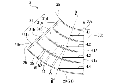
As shown in Fig. 6, the support surface 31 of the base plate 30 is formed to
be
one size larger than the back foil piece 21. Like the back foil piece 21, the
support
surface 31 is formed in a substantially trapezoidal shape in which an apex
side of a fan
shape is cut out and an inner peripheral side and an outer peripheral side are
each arcuate.
That is, the support surface 31 includes two end edges which are separated
from
each other in the circumferential direction and extend from the inner
peripheral side to
the outer peripheral side, an inner peripheral end edge which connects the two
end edges
14
Date Recue/Date Received 2021-08-18
CA 03130741 2021-08-18
on the inner peripheral side, and an outer peripheral end edge which connects
the two end
edges on the outer peripheral side. A boundary of the support surface 31 does
not have
to be clarified by a step or the like.
[0041]
The support surface 31 of the present disclosure is formed by a plurality of
(four
in the present disclosure) inclined surfaces 31a to 31d separated in the
radial direction.
Of the plurality of inclined surfaces 31a to 31d, the inclined surface 31a is
disposed on
the outermost peripheral side, and the inclined surfaces 31b, 31c, and 31d are
disposed in
this order from the inclined surface 31a toward the inside in the radial
direction. The
plurality of inclined surfaces 31a to 31d are inclined with respect to the
flat surface 30b
from an end edge (hereinafter, referred to as an end portion 31A on the other
side of the
support surface 31 in the circumferential direction) extending from the inner
peripheral
side to the outer peripheral side on the other side of the support surface 31
in the
circumferential direction toward one side (toward directions indicated by the
reference
numerals Ll to L4 in Fig. 6) in the above-described first direction. That is,
the support
surface 31 is inclined toward the rear surface side of the base plate 30
toward one side in
the first direction. Further, an axial height of the back foil first end
portion 21a attached
to the end portion 31A on the other side of the support surface 31 in the
circumferential
direction is constant in the radial direction. Further, in the present
disclosure, the
heights of the plurality of inclined surfaces 31a to 31d are constant at
positions parallel to
the back foil first end portion 21a.
[0042]
As shown in Fig. 7, inclination angles 01 to 04 of the plurality of inclined
surfaces 31a to 31d with respect to the flat surface 30b become shallower
(smaller) in
order toward the outside of the insertion hole 30a in the radial direction.
That is, the
Date Recue/Date Received 2021-08-18
CA 03130741 2021-08-18
inclination angle 01 of the inclined surface 31a disposed on the outermost
peripheral side
is the shallowest (smallest), the inclination angle 02 of the inclined surface
31b, the
inclination angle 03 of the inclined surface 31c, and the inclination angle 04
of the
inclined surface 31d are deeper (larger) in this order. The inclination angles
01 to 04
may be set within the range of the initial inclination angle 0 of the inclined
portion 12 of
the top foil piece 11 shown in Fig. 4, and for example, may be set to a value
obtained by
dividing the initial inclination angle 0 into four equal portions.
[0043]
As shown in Fig. 6, among the plurality of inclined surfaces 31a to 31d, a
step
.. 32 is formed between the inclined surfaces adjacent to each other in the
radial direction.
The step 32 of the present disclosure is formed in an arc shape forming a
portion of a
concentric circle with the insertion hole 30a. Further, the step 32 of the
present
disclosure extends from the end portion 31A on the other side of the support
surface 31
in the circumferential direction to an end edge (hereinafter, referred to as
an end portion
31B on one side of the support surface 31 in the circumferential direction)
extending
from the inner peripheral side to the outer peripheral side on one side of the
support
surface 31 in the circumferential direction. In the present disclosure, radial
positions of
the step 32 and the slit 24 match each other. That is, the slit 24 is formed
at the radial
position facing the step 32 in the axial direction.
[0044]
Further, in the present disclosure, the plurality of slits 24 extend to a
position
parallel to the back foil first end portion 21a. That is, a root (groove end)
of each slit 24
is rounded, and a straight line extending in the radial direction connecting
the rounds is
parallel to the back foil first end portion 21a.
Further, the step 32 of the base plate 30 of the present disclosure is formed
from
16
Date Recue/Date Received 2021-08-18
CA 03130741 2021-08-18
a position where a plurality of slits 24 are rounded toward one side (upstream
side in the
rotation direction) in the circumferential direction. Further, in the present
disclosure,
the step 32 becomes larger toward one side in the circumferential direction.
Further, as
in the present disclosure, the step 32 of the base plate 30 may extend to the
other side
(downstream side in the rotation direction) in the circumferential direction
from the
position where the plurality of slits 24 are round. However, the step 32 of
the base plate
30 does not extend beyond the back foil first end portion 21a.
[0045]
Further, in the present disclosure, the four divided regions 25 of the back
foil
piece 21 divided in the radial direction by the slit 24 are supported by the
four inclined
surfaces 31a to 31d divided in the radial direction by the step 32. That is,
the four
divided regions 25 are supported one-to-one by the four inclined surfaces 31a
to 31d.
As for the radial dimensions of one inclined surface and one divided region 25
supported
by the inclined surface, for example, assuming that a dimension of the
inclined surface
(for example, the inclined surface 31a) is represented by W1 and a dimension
of the
divided region 25 is represented by W2, a relationship of W1 > W2 is
satisfied.
[0046]
The base plate 30 having the plurality of inclined surfaces 31a to 31d having
the
above configuration can be formed, for example, by press working as shown in
Figs. 8
and 9.
Figs. 8 and 9 are explanatory views showing a process of forming the plurality
of inclined surfaces 31a to 31d on the base plate 30 according to the first
embodiment of
the present disclosure.
In the press working in this process, a die 100 having a convex portion 101a
on
a press surface as shown in the part (a) of Fig. 8 may be used.
17
Date Recue/Date Received 2021-08-18
CA 03130741 2021-08-18
[0047]
The die 100 includes the convex portion 101a on the press surface of which a
distal surface is inclined at an inclination angle Olin the first direction
(right-left
direction of a paper surface in Fig. 8). That is, the distal surface of the
convex portion
101a extends toward the flat surface 30b of the base plate 30 toward one side
(right side
of the paper surface in Fig. 8) in the first direction. Further, the distal
surface of the
convex portion 101a is formed in a substantially trapezoidal shape similar to
the inclined
surface 31a shown in the plan view of Fig. 6 described above.
[0048]
The flat surface 30b of the base plate 30 is pressed by the die 100 as shown
in a
part (b) of Fig. 8. By this press working, the inclined surface 31a to which
the shape of
the convex portion 101a of the die 100 is transferred is formed on the flat
surface 30b of
the base plate 30.
As a result, as shown in a part (c) of Fig. 8, the inclined surface 31a
inclined at
the inclination angle 01 with respect to the flat surface 30b can be formed on
the flat
surface 30b of the base plate 30.
[0049]
In the next process, a die 100 having a convex portion 101b on a press surface
as
shown in a part (b) of Fig. 9 may be used. The die 100 includes the convex
portion
101b on the press surface whose distal surface is inclined at an inclination
angle 02 in the
first direction (the right-left direction of the paper surface in Fig. 8). A
distal surface of
the convex portion 101b is formed in a substantially trapezoidal shape similar
to the
inclined surface 31b shown in Fig. 6 described above.
[0050]
As shown in a part (b) of Fig. 9, the die 100 presses an inner peripheral side
18
Date Recue/Date Received 2021-08-18
CA 03130741 2021-08-18
from the inclined surface 31a of the flat surface 30b of the base plate 30. By
this press
working, the inclined surface 31b to which the shape of the convex portion
101b of the
die 100 is transferred is formed on the inner peripheral side of the inclined
surface 31a.
In this way, performing stamping (pressing) in order by using the dies having
the
inclination angles 01 to 04 corresponding to the plurality of inclined
surfaces 31a to 31d,
as shown in Fig. 6, the plurality of inclined surfaces 31a to 31d, of which
the inclination
angles become shallower in order toward the outside in the radial direction,
can be
formed on the flat surface 30b of the base plate 30.
[0051]
According to the method for manufacturing the base plate 30, a time required
for
processing the plurality of inclined surfaces 31a to 31d is shortened, and a
cost is
reduced. Further, in this way, by applying the press working which is cheaper
than a
cutting work, the base plate 30 can be easily mass-produced.
The order of pressing the plurality of inclined surfaces 31a to 31d may be in
the
order of deeper inclination angles (in the order of inclined surfaces 31d,
31c, 31b, 31a),
or in any order. Further, when the die 100 includes a plurality of convex
portions
having the plurality of inclination angles 01 to 84, the inclined surfaces 31a
to 31d may
be formed by a single press.
Further, after pressing the entire surface (inclination angle is 0) of the
support
surface 31 with a die having the same inclination angle 01 as the shallowest
inclined
surface 31a, the entire surface (surface having inclination angle 01) of the
support surface
31 excluding the inclined surface 31a may be pressed with a die having the
same
inclination angle 02 as the next shallow inclined surface 3 lb, and thus, the
inclined
surfaces, which are gradually deeper toward the inside in the radial
direction, may be
formed by repeating this.
19
Date Recue/Date Received 2021-08-18
CA 03130741 2021-08-18
[0052]
Next, an operation of the thrust foil bearing 3 including the base plate 30
having
the configuration will be described.
As shown in Fig. 2, the thrust foil bearings 3 are provided on both sides of
the
thrust collar 4 with the thrust collar 4 therebetween. Therefore, the movement
of the
rotating shaft 1 on both sides in the thrust direction can be suppressed.
[0053]
When the rotating shaft 1 rotates in this state and the thrust collar 4 starts
rotating, the thrust collar 4 and the top foil piece 11 rub against each
other, and a
surrounding fluid is pushed into a wedge-shaped space formed between the
thrust collar 4
and the top foil piece 11. Then, when the thrust collar 4 reaches a constant
rotation
speed, a fluid lubricating film is formed between the thrust collar 4 and the
top foil piece
II. The top foil piece 11 is pushed toward the back foil piece 21 by a
pressure of the
fluid lubricating film, and the thrust collar 4 comes out of contact with the
top foil piece
11 and rotates in a non-contact manner.
[0054]
Here, as shown in Fig. 6, the back foil piece 21 is supported by a support
surface
31 inclined with respect to the flat surface 30b of the base plate 30. The
support surface
31 is inclined toward one side (left side of the paper surface in Fig. 6) in
the first
direction orthogonal to the back foil first end portion 21a extending in the
radial direction
of the back foil piece 21. The plurality of inclined surfaces 31a to 31d
forming the
support surface 31 have the same height at the circumferential position
supporting the
back foil first end portion 21a. However, when the inclined surfaces 31a to
31d move
to one side in the circumferential direction from the circumferential position
(for
example, when line B-B is drawn at the same angle in Fig. 6), due to the
difference
Date Recue/Date Received 2021-08-18
CA 03130741 2021-08-18
between the inner and outer circumferences of the base plate 30, an
inclination stroke (for
example, a length of an arrow indicated by the reference numeral L1) of the
inclined
surface disposed on the inner side in the radial direction is shorter than an
inclination
stroke (for example, the length of an arrow indicated by the reference numeral
L2) of the
inclined surface disposed on the outer side in the radial direction. That is,
it can be said
that the inclination stroke becomes longer in the order of reference numerals
LI to L4
from the inner peripheral side to the outer peripheral side.
[0055]
A part (a) of Fig. 10 is an explanatory view describing the operation of the
.. support surface 31 having the plurality of inclined surfaces 31a to 31d
according to the
first embodiment of the present disclosure, and a part (b) of Fig. 10 is an
explanatory
view describing a case of a single support surface 31 (inclined surface) of
the related art
which does not have the plurality of inclined surfaces 31a to 31d as a
comparative
example. Fig. 10 is a schematic cross-sectional view of the circumferential
position
corresponding to line B-B shown in Fig. 6. Line B-B shown in Fig. 6 is a
straight line
extending in the radial direction. That is, Fig. 10 is a cross-sectional view
when the
base plate 30 is cut in the radial direction. In addition, in Fig. 10, in
order to improve
visibility, the inclination of the support surface 31 having the plurality of
inclined
surfaces 31a to 31d shown in the part (a) of Fig. 10 and the inclination of
the single
support surface 31 shown in the part (b) of Fig. 10 are expressed
exaggeratedly. The
actual inclination angle of the support surface 31 is, for example, about 0.1
, and thus,
the support surface 31 looks like a substantially flat surface.
First, when the single support surface 31 (inclined surface) of the related
art
shown in the part (b) of Fig. 10 is described, in the inclined surface 31, the
inclination
stroke on the outer peripheral side is longer than that on the inner
peripheral side due to
21
Date Recue/Date Received 2021-08-18
CA 03130741 2021-08-18
the difference between the inner and outer circumferences of the base plate 30
described
above, and as a result, the outer peripheral side becomes lower than the inner
peripheral
side at the same circumferential position, and the outer peripheral side is
largely
separated from the thrust collar 4 in the axial direction.
[0056]
That is, while a gap between the thrust collar 4 and the top foil piece 11 on
the
inner peripheral side of the base plate 30 is a dimension D, the gap on the
outer
peripheral side of the base plate 30 is a dimension D2 which is larger than
the dimension
D. When the gap between the thrust collar 4 and the top foil piece 11 becomes
large, it
is difficult to form the above-described fluid lubricating film
satisfactorily.
[0057]
On the other hand, although there is the difference between the inner and
outer
circumferences of the base plate 30 described above, in the support surface 31
having the
plurality of inclined surfaces 31a to 31d shown in the pail (a) of Fig. 10 of
the present
disclosure, the inclination angles of the inclined surfaces 31a to 31d with
respect to flat
surface 30b become shallower (smaller) in order toward the outer side of the
insertion
hole 30a in the radial direction. Accordingly, the top foil piece 11 on the
outer
peripheral side is lifted to the thrust collar 4 side via the back foil piece
21, the gap
between the thrust collar 4 and the top foil piece 11 on the outer peripheral
side can be
brought close to the same dimension D1 as the dimension D on the inner
peripheral side.
As a result, the above-described fluid lubricating film can be satisfactorily
formed even
on the outer peripheral side of the base plate 30.
[0058]
Therefore, according to the first embodiment described above, the thrust foil
bearing 3 includes the base plate 30 including the insertion hole 30a through
which the
22
Date Recue/Date Received 2021-08-18
CA 03130741 2021-08-18
rotating shaft 1 is inserted and the support surface 31 disposed around the
insertion hole
30a on one side of the insertion hole 30a in the axial direction, and the back
foil 20
disposed on the support surface 31, the support surface 31 has the plurality
of inclined
surfaces 31a to 31d of which the inclination angles inclined toward the other
side of the
base plate 30 in the axial direction become shallower in order toward the
outside of the
insertion hole 30a in a radial direction, and the back foil 20 is divided into
the plurality of
divided regions 25 in the radial direction by the slit 24, and the plurality
of divided
regions 25 are supported by the plurality of inclined surfaces 31a to 31d.
Therefore, by
adopting the configuration, a load capacity of the thrust foil bearing 3 can
be improved.
[0059]
Further, in the present disclosure, as shown in Fig. 6, the step 32 is formed
between the inclined surfaces 31a to 31d adjacent to each other in the radial
direction
among the plurality of inclined surfaces 31a to 31d, and the slit 24 is formed
at a radial
position facing the step 32 in the axial direction. According to this
configuration, since
the plurality of divided regions 25 can be deformed by the slits 24 at the
same radial
position as the step 32, the plurality of divided regions 25 of the back foil
piece 21 can be
satisfactorily placed on the plurality of inclined surfaces 31a to 31d having
different
inclination angles.
[0060]
[Second Embodiment]
Next, a second embodiment of the present disclosure will be described. In the
following description, the same or equivalent configurations as those in the
above-
described embodiment are designated by the same reference numerals, and
descriptions
thereof will be simplified or omitted.
[0061]
23
Date Recue/Date Received 2021-08-18
CA 03130741 2021-08-18
Fig. 11 is an enlarged plan view showing a support surface 31 of a base plate
30
according to the second embodiment of the present disclosure. Fig. 12 is a
schematic
view when viewed from an arrow C shown in Fig. 11.
As shown in Fig. 11, the second embodiment differs from the above
embodiment in that the number of divisions of the inclined surface 31 of the
support
surface 31 is smaller than the number of divisions of the divided region 25 of
the back
foil piece 21.
[0062]
The support surface 31 of the second embodiment is formed by a plurality of
(two in the present disclosure) inclined surfaces 31f and 31e separated in the
radial
direction. in the inclined surfaces 31f and 31e, the inclined surface 31e is
disposed on
the outermost peripheral side, and the inclined surface 31f is disposed
radially inside
from the inclined surface 31e.
The inclined surfaces 31f and 31e are inclined with respect to the flat
surface
30b from an end portion 31A on the other side of the support surface 31 in the
circumferential direction toward one side in the first direction described
above (toward
directions indicated by arrows indicated by reference numerals L5 and L6 in
Fig. 11).
[0063]
As shown in Fig. 12, inclination angles 05 and 06 of the inclined surfaces 31f
and 31e with respect to the flat surface 30b become shallower (smaller) in
order toward
the outside in the radial direction of the insertion hole 30a. That is, the
inclination angle
05 of the inclined surface 31e disposed on the outermost peripheral side is
shallower
(smaller), and the inclined angle 06 of the inclined surface 31f disposed on
an inner
peripheral side of the inclined surface 31e is deeper (larger). The
inclination angles 05
and 06 may be set within the range of the initial inclination angle 0 of the
inclined
24
Date Recue/Date Received 2021-08-18
CA 03130741 2021-08-18
portion 12 of the top foil piece 11 shown in Fig. 4, and may be set to values
obtained by
dividing the initial inclination angle 0 into two equal portions, for example.
[0064]
As shown in Fig. 11, one step 32 is formed between the inclined surfaces 31f
and 31e adjacent to each other in the radial direction. The step 32 is formed
in an arc
shape forming a portion of a concentric circle with the insertion hole 30a.
Further, the
step 32 of the present disclosure extends from the end portion 31A on the
other side of
the support surface 31 in the circumferential direction to the end portion 31B
on the one
side of the support surface 31 in the circumferential direction. In the
present disclosure,
the step 32 and one of the slits 24 face each other in the axial direction.
That is, in three
slits 24, there are two slits 24 that do not face the step 32 in the axial
direction.
[0065]
Further, in the second embodiment, the four divided regions 25 of the back
foil
piece 21 divided in the radial direction by the slit 24 are supported by the
two inclined
.. surfaces 31f and 31e divided in the radial direction by the step 32. That
is, two of the
four divided regions 25 are supported by each of the two inclined surfaces 31f
and 31e.
According to the second embodiment having the above configuration, a load
capacity of the thrust foil bearing 3 can be improved as in the first
embodiment described
above. Further, in the second embodiment, as compared with the first
embodiment
described above, tilt processing of the support surface 31 is simplified, and
thus, the base
plate 30 can be easily produced.
[0066]
[Third Embodiment]
Next, a third embodiment of the present disclosure will be described. In the
.. following description, the same or equivalent configurations as those in
the above-
Date Recue/Date Received 2021-08-18
CA 03130741 2021-08-18
described embodiment are designated by the same reference numerals, and
descriptions
thereof will be simplified or omitted.
[0067]
Fig. 13 is an enlarged plan view showing a support surface 31 of a base plate
30
according to the third embodiment of the present disclosure.
As shown in Fig. 13, the third embodiment is different from the above
embodiments in that the radial positions of the step 32 of the support surface
31 and the
slit 24 of the back foil piece 21 do not match with each other.
[0068]
In the third embodiment, the four divided regions 25 of the back foil piece 21
radially divided by the slit 24 are supported by the four inclined surfaces
31a to 31d
radially divided by the step 32. However, the inner end edge 25a of the
divided region
25 extends radially inward from a step 32 on a radial inner end edge side of
the inclined
surface (for example, the inclined surface 31a) supporting the divided region
25.
[0069]
That is, the inner end edge 25a of the divided region 25 supported by the
inclined surface (for example, the inclined surface 31a) having a shallow
inclination
angle overhangs on the inclined surface (for example, the inclined surface 3
lb) having a
deep inclination angle like an eaves. Therefore, when the radial dimension of
one
inclined surface (for example, the inclined surface 31a) and the radial
dimension of one
divided region 25 supported by the inclined surface are represented by W1 and
W2, there
may be a case where a relationship of W1 <W2 is satisfied.
Even with the above configuration, the plurality of divided regions 25 of the
back foil piece 21 can be satisfactorily placed on the plurality of inclined
surfaces 31a to
3Id having different inclination angles, and the plurality of divided regions
25 can be
26
Date Recue/Date Received 2021-08-18
CA 03130741 2021-08-18
independently deformed by the slit 24.
[0070]
Although embodiments of the present disclosure have been described above
with reference to the drawings, the present disclosure is not limited to the
above
embodiments. The various shapes and combinations of constituent members shown
in
the above-described embodiments are examples, and can be variously changed
based on
design requirements or the like within a scope of the present disclosure
defined in claims
described below.
[Industrial Applicability]
[0071]
According to a thrust foil bearing and a method for manufacturing a base plate
of a thrust foil bearing of the present disclosure, a load capacity of the
thrust foil bearing
can be improved.
[Reference Signs List]
[0072]
1: Rotating shaft (shaft)
2: Impeller
3: Thrust foil bearing
10: Top foil
11: Top foil piece
12: Inclined portion
12a: End portion
13: Attachment portion
14: Bent portion
20: Back foil
27
Date Recue/Date Received 2021-08-18
CA 03130741 2021-08-18
21: Back foil piece
21a: Back foil first end portion
21b: Back foil second end portion
22: Support portion
22a: Peak portion
22b: Valley portion
24: Slit
25: Divided region
25a: Inner end edge
30: Base plate
30a: Insertion hole
30b: Flat surface
31: Support surface
31A: End portion
31B: End portion
31a: Inclined surface
31b: Inclined surface
31c: Inclined surface
31d: Inclined surface
31e: Inclined surface
31f: Inclined surface
32: Step
100: Die
101a: Convex portion
101b: Convex portion
28
Date Recue/Date Received 2021-08-18
CA 03130741 2021-08-18
61: Inclination angle
0 2: Inclination angle
0 3: Inclination angle
0 4: Inclination angle
0 5: Inclination angle
0 6: Inclination angle
15
29
Date Recue/Date Received 2021-08-18