Note: Descriptions are shown in the official language in which they were submitted.
CA 03130896 2021-08-19
WO 2020/172399
PCT/US2020/019026
ROTATING INTERNAL COMBUSTION ENGINE
CROSS-REFERENCE TO RELATED APPLICATIONS
[001] The present application claims the benefit of United States Provisional
Patent
Application No. 62/808,174 (pending), filed on February 20, 2019, entitled
"Air-Cooled,
Rotating Internal Combustion Engine", the entirety of which is incorporated
herein by
reference.
FIELD
[002] The present disclosure relates to systems, apparatus, and methods for
generating motive
power, including rotating internal combustion engines.
BACKGROUND
[003] An internal combustion engine (ICE) works by combusting fuel in the
presence of an
oxidizer to form an expanding gas that, in-turn, applies force to a mechanical
apparatus,
typically pistons that move in response to the force, ultimately driving
another mechanical
apparatus (e.g., rotating the wheels of a vehicle). Such piston engines
include four stages or
strokes, including a loading stage, a compression stage, a detonation stage,
and an exhaust
stage.
[004] Typical gas turbine engines have a section that is devoted only to
combustion, which is
positioned between a compressor section and a turbine section. The combustion
process of such
typical gas turbine engines occurs at constant pressure, where gas (e.g., air)
continuously flows
in from the compressor section into the combustion section, fuel is
continuously added by
injectors into the combustion section, and combustion occurs continuously in
the combustion
section.
BRIEF SUMMARY
[005] One aspect of the present disclosure includes a combustion turbine
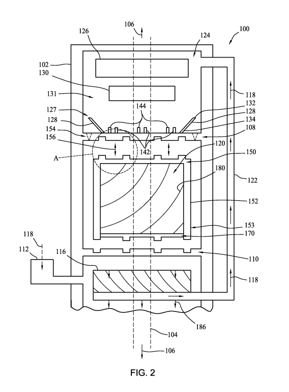
engine. The engine
includes an air intake and a combustion turbine. The combustion turbine
includes a shroud and
turbine blades coupled to or integral with the shroud. The turbine blades are
positioned within
the shroud, and space between adjacent turbine blades at least partially
define combustion
chambers, the combustion chambers having constant volumes. An intake end of
the combustion
turbine includes intake inlets into the combustion chambers, and an exhaust
end of the
combustion turbine includes exhaust outlets out of the combustion chambers.
The engine
1
CA 03130896 2021-08-19
WO 2020/172399
PCT/US2020/019026
includes a drive shaft coupled to the combustion turbine, such that rotation
of the combustion
turbine rotates the drive shaft. A top fixed plate of the engine includes
intake inlets positioned
adjacent the intake end, and a bottom fixed plate of the engine includes
exhaust outlets
positioned adjacent the exhaust end. The combustion turbine is positioned
between the top and
bottom fixed plates. The combustion turbine is rotatable relative to the top
fixed plate to allow
passage of intake air into the combustion chambers through the intake inlets,
and is rotatable
relative to the bottom fixed to exhaust combustion gases through the exhaust
outlets.
[006] Another embodiment of the present disclosure includes a combustion
turbine engine
that includes an air intake and a stationary combustor. The stationary
combustor includes a
shroud and combustion chamber walls coupled to or integral with the shroud.
The combustion
chamber walls are positioned within the shroud, and space between adjacent
combustion
chamber walls at least partially define combustion chambers. An intake end of
the combustion
chambers includes intake inlets into the combustion chambers, and an exhaust
end of the
combustion chambers includes exhaust outlets out of the combustion chambers. A
top plate of
the engine includes intake inlets positioned adjacent the intake end, and a
bottom plate of the
engine includes exhaust outlets positioned adjacent the exhaust end. The
stationary combustor
is positioned between the top and bottom plates. The top plate includes intake
inlets, which
may be nozzles, to direct intake air into the combustion chambers and the
bottom plate includes
exhaust outlets, which may be nozzles, positioned to direct exhaust out of the
combustion
chambers circumferentially about the stationary combustor to create thrust to
rotate the top and
bottom plates. A drive shaft is coupled with the top and bottom plates such
that rotation of the
top and bottom plates rotates the drive shaft. The top and bottom plates are
rotatable relative to
the stationary combustor to allow passage of intake air into the combustion
chambers through
the intake inlets and to exhaust combustion gases through the exhaust outlets.
.. [007] Another embodiment of the present disclosure includes a method of
generating motive
force using a combustion turbine engine. The method includes providing fuel
and intake air
into an intake end of combustion chambers. The combustion chambers are at
least partially
defined by space between blades of a combustion turbine. The blades are
coupled with a drive
shaft. The method includes closing the intake end and exhaust end of the
combustion chambers
and combusting the fuel and intake air mixture within the closed, constant
volume, combustion
chambers. The combusting forms combustion gases. The method includes opening
the exhaust
end of the combustion chambers and exhausting the combustion gases from the
combustion
chambers. Without being bound by theory, using Newton's Third Law, the thrust
from
2
CA 03130896 2021-08-19
WO 2020/172399
PCT/US2020/019026
exhausting the combustion gases drives rotation of the blades, and rotation of
the blades drives
rotation of the drive shaft.
[008] Another embodiment of the present disclosure includes a method of
generating motive
force using a combustion turbine engine. The method includes providing fuel
and intake air
into an intake end of combustion chambers. The combustion chambers are at
least partially
defined by space between blades of a stationary combustor. The method includes
closing the
intake end and exhaust end of the combustion chambers and combusting the fuel
and intake air
mixture within the closed combustion chambers. The combusting forms combustion
gases. The
method includes opening the exhaust end of the combustion chambers and
exhausting the
combustion gases from the combustion chambers. The stationary combustor is
positioned
between a top plate and a bottom plate of the combustion turbine engine. The
top plate includes
intake inlets positioned adjacent the intake end and the bottom plate includes
exhaust outlets
positioned adjacent the exhaust end. The top plate includes intake inlets,
which may be nozzles,
positioned to direct intake air into the combustion chambers and the bottom
plate includes
exhaust outlets, which may be nozzles, positioned to direct exhaust out of the
combustion
chambers circumferentially about the stationary combustor to create thrust to
rotate the top and
bottom plates. The top and bottom plates are coupled with a drive shaft such
that rotation of
the top and bottom plates rotates the drive shaft. The top and bottom plates
are rotatable relative
to the stationary combustor to allow passage of intake air into the combustion
chambers
through the intake inlets and to exhaust combustion gases through the exhaust
outlets.
BRIEF DESCRIPTION OF THE DRAWINGS
[009] So that the manner in which the features and advantages of the systems,
apparatus,
and/or methods of the present disclosure may be understood in more detail, a
more particular
description, briefly summarized above, may be had by reference to the
embodiments thereof
which are illustrated in the appended drawings that form a part of this
specification. It is to be
noted, however, that the drawings illustrate only various exemplary
embodiments and are
therefore not to be considered limiting of the disclosed concepts as it may
include other
effective embodiments as well.
.. [0010] FIG. 1A is a schematic of a combustion turbine engine.
[0011] FIG. 1B is another schematic of a combustion turbine engine.
[0012] FIG. 2 depicts a combustion turbine engine
[0013] FIG. 3 depicts a top fixed plate of the engine with four intake inlets.
[0014] FIG. 4 depicts an intake end of a combustion turbine with four intake
inlets.
3
CA 03130896 2021-08-19
WO 2020/172399
PCT/US2020/019026
[0015] FIG. 5 depicts a combustion chamber of a combustion turbine.
[0016] FIG. 6 depicts an exhaust end of a combustion turbine with four exhaust
outlets.
[0017] FIG. 7 depicts a bottom fixed plate of the engine with four exhaust
outlets.
[0018] FIG. 8 depicts a portion of an internal combustion piston.
[0019] FIG. 9 depicts detail view A of FIG. 2.
[0020] FIG. 10A depicts an exploded view of portions of a combustion turbine.
[0021] FIG. 10B depicts a combustion turbine with the inlets of the top fixed
plate in alignment
with the inlets of the top rotating plate.
[0022] FIG. 10C depicts a combustion turbine with the inlets of the top fixed
plate out of
alignment with the inlets of the top rotating plate.
[0023] FIG. 10D depicts a combustion turbine with the inlets of the bottom
fixed plate out of
alignment with the inlets of the bottom rotating plate.
[0024] FIG. 10E depicts a combustion turbine with the inlets of the bottom
fixed plate in
alignment with the inlets of the bottom rotating plate.
[0025] FIGS. 11A and 11B depict the combustion turbine engine.
[0026] FIG. 12 is an illustration of a combustion sequence of the engine.
[0027] FIG. 13 is a graph of pressure vs. specific volume for an idealize
process.
[0028] FIG. 14 is a graph of pressure vs. specific volume showing the increase
in work output
resulting from increased compression ratio.
[0029] FIG. 15 is a graph of pressure vs. specific volume showing the effect
of leakage and
pressure drop losses entering the combustion chamber.
[0030] FIG. 16 is a timeline of an engine sequence.
[0031] FIG. 17 is a graph of pressure vs. specific volume showing the effect
of leakage and
pressure drop losses exiting the combustion chamber.
[0032] FIG. 18 is a graph of normalized turbine efficiency as a function of
blade speed ratio.
[0033] FIG. 19 is a schematic illustrating aerodynamic lift.
[0034] FIG. 20 is a schematic illustrating a combustion event within a
combustion chamber.
[0035] FIG. 21 is a chematic illustrating a stationary combustion chamber with
rotaing plates.
[0036] FIGS. 22A-22D are graphs of pressure vs volume for Otto, Diesel,
Brayton, and
detonation cycles, respectively.
[0037] Systems, apparatus, and methods according to the present disclosure
will now be
described more fully with reference to the accompanying drawings, which
illustrate various
exemplary embodiments. Concepts according to the present disclosure may,
however, be
embodied in many different forms and should not be construed as being limited
by the
4
CA 03130896 2021-08-19
WO 2020/172399
PCT/US2020/019026
illustrated embodiments set forth herein. Rather, these embodiments are
provided so that this
disclosure will be thorough as well as complete and will fully convey the
scope of the various
concepts to those skilled in the art and the best and preferred modes of
practice.
DETAILED DESCRIPTION
[0038] Certain embodiments of the present disclosure include systems,
apparatus, and methods
for generating motive force. Some embodiments include a rotating internal
combustion engine,
which may be air-cooled, as well as to methods of making and using the same.
Engine Schematic
[0039] With reference to FIG. 1A, a system including an engine in accordance
with some
embodiments of the present disclosure is depicted. FIG. 1A is a schematic
showing the relative
arrangement and positioning of components in accordance with one embodiment.
However,
the systems and engines disclosed herein are not limited to the arrangement
shown in FIG. 1A.
System 1000 includes engine 100. The engines disclosed herein include a
component that
functions as both a combustion chamber for combustion of fuel and as a turbine
for the
harvesting of energy released during the combustion. In some embodiments, this
component is
referred to herein as a combustion turbine or as a rotating cylinder.
Combustion turbine 152
may include one or more chambers within which combustion occurs. The chambers
of
combustion turbine 152 may be shaped and/or arranged to additionally function
as turbine
blades, such that fluids moving therein (e.g., expanding gases) impart force
upon the walls of
the combustion chambers (blades). For example, fuel mixture 114, such as a
mixture of feed
air 118 and gasoline 184, may be combusted within the constant volume
combustion chambers
of combustion turbine 152, forming combustion gases 186. The equal and
opposite thrust force
imparted by the exhaust of such fluids (combustion gases) onto the combustion
chambers
causes combustion turbine 152, or portions thereof, to rotate. As used herein,
"constant
volume" in reference to a combustion chamber refers to a combustion chamber
that has a
constant volume when combustion is occurring within the chamber. For example,
a typical
piston engine is not a constant volume combustion chamber because the volume
of the
combustion chamber changes with the movement of the piston. As used herein,
"constant
volume" in reference to a combustion process or event refers to the occurrence
of combustion
with a constant volume combustion chamber.
[0040] In some embodiments, combustion turbine 152 is coupled with drive shaft
104, such
that rotation of combustion turbine 152 causes drive shaft 104 to rotate.
Drive shaft 104 may,
in turn, be coupled to another component 111, such that rotation of drive
shaft 104 drives
5
CA 03130896 2021-08-19
WO 2020/172399
PCT/US2020/019026
component 111, causing component 111 to rotate or otherwise move. For example,
component
111 may be or include one or more wheels, fans, propellers, pumps, generators,
or other devices
in which the mechanical energy of rotating drive shaft 104 may be transferred,
utilized, and/or
converted. Thus, in some embodiments combustion turbine 152 drives the
rotation of the
wheels of a vehicle, drives the rotation of fans, drives the rotation of
propellers of a vehicle
(e.g., an airplane or boat), or drives a generator for the production of
electricity. In some
embodiments, combustion gases 186 exit combustion turbine 152, and at least
some remaining
energy of combustion gases 186 is harvested downstream of combustion turbine
152, such as
via auxiliary turbine 113 or other rotation expander coupled with drive shaft
104. The energy
harvested by auxiliary turbine 113 may be used to power other components of
system 1000.
For example, in some embodiments, air 118 is compressed prior to entering the
combustion
chambers of combustion turbine 152 via passage through at least one compressor
130, and the
energy harvested by auxiliary turbine 113 is used to at least partially power
the at least one
compressor 130. As shown in FIG. 1A, compressor 130 is also coupled with
combustion
turbine 152, as indicated via 117, such that compressor 130 is capable of
providing compressed
air to combustion turbine 152. In some embodiments, the energy harvested by
auxiliary turbine
113 is provided to compressor 130 as mechanical energy through drive shaft
104. In other
embodiments, the energy harvested by auxiliary turbine 113 is converted to
electrical energy
prior to being provided to compressor 130. In FIG. 1A, engine 100 includes
compressor 130,
combustion turbine 152, auxiliary turbine 113, and drive shaft 104. However,
engine 100 is not
limited to including these components. In some embodiments, some of the
components of
engine 100 in FIG. 1A may be eliminated (e.g., the auxiliary turbine may be
eliminated in some
embodiments). Also, in some embodiments, additional components may be added to
engine
100 (e.g., more than one compressor may be included upstream of combustion
turbine 152).
.. [0041] FIG. 1B depicts another embodiment of system 1000. System 1000 is
substantially
similar to the system of FIG. 1A. However, in FIG. 1B, air 118 first passes
through charger
116, which may be a turbocharger, supercharger, or twincharger. Air 118 then
flows from
charger 116 to at least one compressor. The charger 116 may be driven, at
least partially, by
exhaust 186.
Engine Intake and Compression
[0042] FIG. 2 depicts another embodiment of engine 100, including a
turbocharger and two
stages of compression, prior to combustion. Engine 100, also referred to as
ICE, includes
exterior cylinder 102, which at least partially defines a housing that
contains all or at least some
of the internal components of engine 100. Exterior cylinder 102 may be a
relatively thick,
6
CA 03130896 2021-08-19
WO 2020/172399
PCT/US2020/019026
heavy, metal cylinder that houses all or most of the internal components of
engine 100. For
example, external cylinder 102 may be at least partially composed of steel.
[0043] Moving along the fuel cycle of engine 100, from intake to exhaust, the
operation of
engine 100 will now be described. In some embodiments, the engines disclosed
herein are
naturally aerated. In other embodiments, the engines disclosed herein are
forced induction
engines that include a turbocharger, a supercharger, or a twincharger (i.e., a
combination of a
turbocharger and a twincharger) positioned to receive air and forcibly inject
the air toward the
combustion chamber of the engines, and into one or more compressors (e.g.,
compressors 126
and 130). For example, in FIG. 2, engine 100 includes forced induction device
116, which may
be a turbocharger, a supercharger, or a twincharger. A turbocharger is a
forced induction device
that forces compressed air toward the combustion chamber of an engine.
Turbochargers are
powered by a turbine that is driven by the engine's exhaust gas. Thus, when
forced induction
device 116 is a turbocharger, forced induction device 116 may be positioned in
the exhaust
stream of the engine 100. A supercharger is a mechanically driven forced
induction device,
which may be mechanically driven by the engine, such as by a belt attached to
the drive shaft
of the engine. With reference to FIG. 2, engine 100 includes air inlet 112,
through which air
118 enter into engine 100. Forced induction device 116, here shown as a
turbocharger
positioned within the exhaust stream of engine 100, receives air 118 from
inlet 112. Forced
induction device 116 forces air 118 towards the combustion chambers 120 of
combustion
turbine 152. While described as air, in some embodiments, engine 100 utilizes
another oxidizer,
such as pure oxygen.
[0044] From forced induction device 116, feed-air 118 passes through feed
conduit 122 and
into compression chamber 124, also referred to as feed chamber, of engine 100.
Within
compression chamber 124, feed-air 118 passes through a series of air-
compressors, including
first air compressor 126 and second air compressor 130. While air 118 is shown
in FIG. 2 as
passing through two sequential air compressors, engine 100 is not limited to
including two
sequential air compressors, and may include only one air compressor or more
than two
sequential air compressors. As air 118 enters compression chamber 124, air 118
passes through
first air compressor 126. Within first air compressor 126 (also referred to as
low-pressure air
compressor) air is compressed, such that air 118 exiting first air compressor
126 is more
compressed than air entering first air compressor 126. After exiting first air
compressor 126,
air 118 enters and is compressed within second air compressor 130 (also
referred to as high-
pressure air compressor). Within second air compressor 130, air is compressed,
such that air
118 exiting second air compressor 130 is more compressed than air entering
second air
7
CA 03130896 2021-08-19
WO 2020/172399
PCT/US2020/019026
compressor 130. In some embodiments, one or more of the air compressors are
coupled with
and driven by drive shaft 104 of engine 100, such that rotation of drive shaft
104 drives the
compressors. For example, a belt of other component may be coupled between
drive shaft 104
and the compressors, such that the rotation of drive shaft 104 moves the belt
and the movement
of the belt drives the compressors.
[0045] From second air compressor 130, air 118 passes through air
pressurization nozzle 127,
which may be arranged concentrically within engine 100 relative to the outlet
of compressor
130 and the intake inlet of combustion turbine 152. Air pressurization nozzle
127 may be
integral with, attached to, or otherwise coupled with top fixed plate 108 of
combustion turbine
152. Air pressurization nozzle 127 includes funnel wall 128, which may be a
relatively short,
angled wall. In some embodiments, funnel wall 128 does not engage external
cylinder 102.
From top end 132 of funnel wall 128 to top fixed plate 108, funnel wall 128
slants inward, at a
slope relative to axis 106, such that bottom end 134 of funnel wall 128
defines an opening
having a smaller diameter than the opening defined by top end 132 of funnel
wall 128. Funnel
wall 128 receives compressed feed-air 118 from high-pressure air-compressor
130, and funnels
the compressed feed-air 118 into the combustion chambers 120. Air
pressurization nozzle 127
further compresses feed-air 118 before feed-air 118 flows into the inlet
openings on top fixed
plate 108. In some embodiments, the bottom end 134 of funnel wall 128 is
coupled with top
fixed plate 108 at a location in the outer one-third of top fixed plate 108
(i.e., is positioned
closer to the circumferential perimeter of top fixed plate 108 than to a
center point of top fixed
plate 108).
Combustion Turbine Engine
[0046] With reference to FIGS. 2, 3, 4, and 5, the intake end of combustion
turbine 152 is
described. The present disclosure includes combustion turbine engines that are
piston-less, i.e.,
do not include pistons. The engine includes top fixed plate 108 and bottom
fixed plate 110.
Positioned between top fixed plate 108 and bottom fixed plate 110 is
combustion turbine 152.
Combustion turbine 152 includes blades 180 positioned within a shroud 153. The
blades 180
(turbine blades) are movable relative to shroud 153. The spaces between the
blades 180 define
the combustion chambers 120 of combustion turbine 152, with the blades 180
extending
between an intake side 150 of combustion chamber 152 and a bottom side 170 of
combustion
chamber 152. The intake end of the combustion turbine 152 includes the top
fixed plate 108
and the intake side 150 of the rotating combustion turbine 152. Top fixed
plate 108 may be a
relatively thick, fixed, metal plate that is attached to the internal
circumference of the walls of
external cylinder 102.
8
CA 03130896 2021-08-19
WO 2020/172399
PCT/US2020/019026
[0047] Top fixed plate 108 includes openings or holes defined therethrough,
here shown as
inlets 136. In some embodiments, top fixed plate 108 has an even number of
inlets 136. In
some embodiments, inlets 136 are arranged and spaced apart in a symmetrical
pattern on top
fixed plate 108. Top fixed plate 108 may include any number of inlets 136,
such as from 1 to
12, or from 2 to 10, or from 4 to 8, or from 5 to 7. In some embodiments, top
fixed plate 108
has at least four inlets 136. The number of inlets 136 may match the number of
combustion
chambers within combustion turbine 152. In certain embodiments, inlets 136 may
be positioned
in the middle two-thirds of top fixed plate 108, between center point 140 and
circumferential
perimeter 138. Inlets 136 allow for the passage of compressed feed-air 118
from compression
chamber 124 into combustion chamber 120. Between inlets 136, are wedges of the
material of
which top fixed plate 108 is at least partially composed, herein referred to
as power wedges
146.
[0048] Engine 100 includes one or more ignition devices and one or more fuel
injection
devices. As shown in FIG. 3, in some embodiments, the ignition and fuel
injection devices of
engine 100 are coupled with top fixed plate 108, which, in some embodiments,
may be
positioned on the outside of compression chamber 124. Top fixed plate 108
includes ignition
apparatus 142 for use in ignition of a fuel and air mixture within combustion
chambers 120.
Each ignition apparatus 142 may be positioned in or on top fixed plate 108 at
locations between
inlets 136. Top fixed plate 108 may include any number of ignition apparatus
142, such as from
1 to 12, or from 2 to 11, or from 3 to 10, or from 4 to 8, or from 5 to 7. In
some embodiments,
top fixed plate 108 has at least four ignition apparatus. The number of
ignition apparatus may
match the number of combustion chambers. In certain embodiments, the ignition
apparatus is
or includes spark plugs.
[0049] In some embodiments, each fuel injection port 144 may be coupled with
and/or in
communication with a Full Authority Digital Engine Controller (FADEC), which
may be
positioned outside of the engine cylinder, and may control the operation of
engine 100, or
components thereof For example, the FADEC may control when and how much fuel
is injected
into combustion chamber, and when ignition apparatus is actuated (e.g., when a
spark is
generated by a spark plug). A FADEC is a system that includes a digital
computer, also referred
to as an electronic engine controller (EEC) or an engine control unit (ECU),
as well as related
accessories that control some or all aspects of engine performance.
[0050] As shown in FIG. 3, in some embodiments, the fuel injection devises of
engine 100 are
fuel injection ports in top fixed plate 108. Top fixed plate 108 includes fuel
injection ports 144
for use in the injection of fuel into combustion chambers 120. Some exemplary
fuels that may
9
CA 03130896 2021-08-19
WO 2020/172399
PCT/US2020/019026
be injected include gasoline and diesel fuel. Each fuel injection port 144 may
be positioned in
or on top fixed plate 108 at locations between inlets 136. Top fixed plate 108
may include any
number of fuel injection ports 144, such as from 1 to 12, or from 2 to 11, or
from 3 to 10, or
from 4 to 8, or from 5 to 7. In some embodiments, top fixed plate 108 has at
least four fuel
injection ports. The number of fuel injection ports may match the number of
combustion
chambers.
[0051] In some embodiments, the ignition and fuel injection components (e.g.,
ignition
apparatus 142 and fuel injection ports 144) are positioned outside of external
cylinder 102. For
example, the broken lines 109 in FIG. 3 represent an alternative perimeter of
top fixed plate
108, such that ignition apparatus 142 and fuel injection ports 144 are
positioned outside of top
fixed plate 108 and outside of external cylinder 102.
[0052] FIG. 4 depicts an exemplary view of the combustion turbine 152 at the
intake side 150.
The combustion turbine 152 may be similar to the top fixed plate 108, with the
exception that
top combustion turbine 152 is not coupled with external cylinder 102 and can,
thus, move
relative to external cylinder 102, and combustion turbine 152 does not include
fuel injection
ports or ignition apparatus. Combustion turbine 152 may be a relatively thick,
metal plate that
is coupled to drive shaft 104. Combustion turbine 152 includes openings or
holes defined
through the intake side 150, here shown as inlets 166 into combustion chambers
120. In some
embodiments, combustion turbine 152 has an even number of inlets 166. In some
embodiments, inlets 166 are arranged and spaced apart in a symmetrical pattern
on combustion
turbine 152. Combustion turbine 152 may include any number of inlets 166, such
as from 1 to
12, or from 2 to 10, or from 4 to 8, or from 5 to 7. In some embodiments, top
rotating plate 150
has at least four inlets 166. In certain embodiments, inlets 166 may be
positioned in the middle
two-thirds of combustion turbine 152 at the intake side 150, between center
point 141 and
circumferential perimeter 139. When inlets 136 and inlets 166 are aligned,
inlets 166 allow for
the passage of compressed feed-air 118 from inlets 136 into combustion
chambers 120.
Between inlets 166, are wedges 168 of the material of which blades 180 are at
least partially
composed. The wedges 168 are also referred to as power wedges.
[0053] Thus, from second air compressor 130, air 118 passes through inlets 136
that are formed
in top fixed plate 108 and through inlets 166 that are formed in the intake
side 150 of
combustion turbine 152, and enters combustion chambers 120. With air 118
inside of
combustion chambers 120, the combustion turbine 152 rotates until inlets 136
and inlets 166
are no longer aligned and wedges 146 are aligned with inlets 166.
CA 03130896 2021-08-19
WO 2020/172399
PCT/US2020/019026
[0054] As shown in FIG. 5, when wedges 146 are aligned with inlets 166, fuel
184 is injected
into combustion chamber 120 via fuel injector 144 and ignition apparatus 142
provides spark
182 or other igniting medium within combustion chamber 120, resulting in
ignition of fuel 184
in the presence of air 118 within combustion chamber 120. The ignition of the
mixture of air
.. 118 and fuel 184 results in the formation of combustion gases within
combustion chamber 120.
The combustion gases flow through combustion chamber 120, toward the exhaust
end 170 of
the combustion turbine 152, imparting a thrust force with a magnitude as large
as the exhaust
force upon the combustion chamber walls 180 (also referred to as combustion
blades) that
define combustion chamber 120. Because the exhaust outlets 176 of the exhaust
end 170 are
askew from the intake inlets 166, the combustion chamber walls 180 are curved
as the
combustion chamber extends from the inlets 166 to the outlets 176. This
results in the
expanding combustion gases exerting thrust force upon the combustion chamber
walls 180 at
angles oblique or perpendicular to the surfaces of the combustion chamber
walls 180. The
thrust force imparted on combustion chamber walls 180 drives the rotation of
combustion
.. turbine 152 which, in turn, drives the rotation of drive shaft 104, which
may, in turn, drive the
rotation of another component, such as the wheels of a vehicle.
[0055] Drive shaft 104 is positioned and extends along axis 106. Axis 106 may
be coincident
with or parallel with a longitudinal centerline of engine 100. In some
embodiments, all or most
of the internal components of engine 100 are attached to or otherwise coupled
with drive shaft
.. 104. In some such embodiments, exterior cylinder 102 is not attached to or
coupled with drive
shaft 104. In some such embodiments, top fixed plate 108 and bottom fixed
plate 110 of engine
100 are coupled to or integral with drive shaft 104 via bearings, such that
drive shaft 104 is
movable relative to top fixed plate 108 and bottom fixed plate 110.
[0056] In some embodiments, one or more air-cooling holes 154 are located on
the outside of
.. top fixed plate 108 and/or within the walls of the combustion turbine 152.
Air-cooling holes
154 provide for a cooling flow of air resulting from the pressure drop into
the lower pressure
area surrounding combustion turbine 152 where the combustion occurs. In some
embodiments,
air-cooling holes may incorporate pressure controllers to regulate the air
pressure in the high-
pressure pulsation damper and retention chamber 131.
.. [0057] With combustion chambers 120 allowing combustion turbine 152 to
function as a
combustion chamber of engine 100 and combustion chamber walls 180 allowing
combustion
turbine 152 to function as a turbine of engine 100, combustion turbine 152 is
capable of
extracting power using both combustion action and turbine action. Fuel 184 and
air 118 flow
periodically and intermittently into combustion turbine 152, and combustion
takes place within
11
CA 03130896 2021-08-19
WO 2020/172399
PCT/US2020/019026
combustion chambers 120, periodically and intermittently, with combustion
occurring within
the turbine, rather than upstream of the turbine. Thus, in some embodiments,
the present
disclosure includes a turbine having a chamber therein within which combustion
occurs.
[0058] The outlets 176 of exhaust end 170 of combustion turbine 152 and the
outlets 101 of
.. bottom fixed plate 110 define at least a portion of the exhaust end of
engine 100. Exhaust end
170 has the same number of symmetrically positioned openings, outlets 176, as
the intake end
150. FIG. 6 depicts an embodiment of exhaust end 170, including outlets 176
and wedges 168
(also referred to as exhaust wedges). In some embodiments, exhaust end 170 has
an even
number of outlets 176. In some embodiments, outlets 176 are arranged and
spaced apart in a
.. symmetrical pattern. Exhaust end may include any number of outlets 176,
such as from 1 to
12, or from 2 to 10, or from 4 to 8, or from 5 to 7. In some embodiments,
exhaust end 170 has
at least four outlets 176. In certain embodiments, outlets 176 may be
positioned in the middle
two-thirds of exhaust end 170, between center point 141 and circumferential
perimeter 173.
[0059] Bottom fixed plate 110 may have the same number of symmetrically
positioned
openings as top fixed plate 108. FIG. 7 depicts an embodiment of bottom fixed
plate 110,
including outlets 101 and exhaust wedges 103. In some embodiments, bottom
fixed plate 110
has an even number of outlets 101. In some embodiments, outlets 101 are
arranged and spaced
apart in a symmetrical pattern on bottom fixed plate 110. Bottom fixed plate
110 may include
any number of outlets 101, such as from 1 to 12, or from 2 to 10, or from 4 to
8, or from 5 to
7. In some embodiments, bottom fixed plate 110 has at least four outlets 101.
In certain
embodiments, outlets 101 may be positioned in the middle two-thirds of bottom
fixed plate
110, between center point 107 and circumferential perimeter 105. Wedges 103
include the
material of which bottom fixed plate 110 is at least partially composed, such
as steel. Bottom
fixed plate 110 may be a relatively thick, fixed, metal plate that is attached
to or otherwise
coupled with the circumference of the exterior cylinder 102 walls. Bottom
fixed plate 110,
similar to top fixed plate 108, may have an even number of symmetrically
placed openings
(e.g., four or more) positioned substantially in the middle two-thirds of
bottom fixed plate 110.
When outlets 176 and outlets 101 are aligned, outlets 101 and 176 allow for
the passage of
exhaust 186 out of combustion chambers 120.
.. [0060] Each of top fixed plate 108, combustion turbine 152, and bottom
fixed plate 110 include
a hole, holes 189a-189d. Holes 189a-189d are aligned such that drive shaft
104, extending
along axis 106, passes through holes 189a-189d. Drive shaft 104 may be coupled
with
combustion turbine 152 at holes 189b and 189c, such that rotation of
combustion turbine 152
rotates drive shaft 104. In some embodiments, drive shaft 104 is coupled with
top and bottom
12
CA 03130896 2021-08-19
WO 2020/172399
PCT/US2020/019026
fixed plates at holes 189a and 189d, such that drive shaft 104 can rotate
relative to top and
bottom fixed plates without causing top and bottom fixed plates to rotate.
[0061] Combustion turbine 152 includes a cylinder or shroud 153. Shroud 153
may be a
relatively thick walled, hollow, metal (e.g., steel) cylinder. Shroud 153 may
be coupled with
the intake end 150 and exhaust end 170 of the combustion turbine 152. Shroud
153 may be
smaller in diameter than top fixed plate 108. Combustion turbine 152 may be
coupled with
drive shaft 104. In some such embodiments, intake end 150 and exhaust end 170
of combustion
turbine 152 are coupled with drive shaft 104 where drive shaft 104 passes
through holes 189b
and 189c. Rotation of combustion turbine 152 causes drive shaft 104 to rotate
about axis 106.
That is, rotation of combustion turbine 152 drives drive shaft 104 to
correspondingly rotate.
[0062] With reference to FIGS. 2 and 8, in some embodiments, tolerances 156
between top
fixed plate 108 and the intake end 150 and between bottom fixed plate 110 and
the exhaust end
170 are the same or substantially the same as the tolerance 158 between a
piston 160 and
sidewalls 162 thereof in an internal combustion piston engine.
[0063] With reference to both FIGS. 2 and 9, positioned between top fixed
plate 108 and the
intake end 150 are rings 164, which may be the same or substantially similar
to rings that are
used on a piston engine piston. Rings 164 are positioned on the outside and
inside of inlets 166
and blast nibs 169 that are formed through top rotating plate 150. Bearings
172 are positioned
between the engagement of top fixed plate 108 and drive shaft 104, such that
the drive shaft
104 can rotate relative to the top fixed plate 108. Blast nibs 169 are built
into or otherwise
coupled with or incorporated into top rotating plate 150 and top fixed plate
108 to protect rings
164 and bearings 172, if needed. The bottom fixed plate 110 may be configured
in the same
manner as the top fixed plate 108 as described above with respect to FIGS. 2
and 9, with rings
positioned between bottom fixed plate 110 and the exhaust end 170. Rings may
be positioned
on the outside and inside of outlets 176 and blast nibs that are formed
through bottom rotating
plate 170. Bearings may also be positioned between the engagement of bottom
fixed plate 110
and drive shaft 104, such that the drive shaft 104 can rotate relative to the
bottom fixed plate
110. Blast nibs may be built into or otherwise coupled with or incorporated
into bottom rotating
plate 170 and bottom fixed plate 110 to protect the rings and bearings, if
needed.
[0064] FIG. 10A depicts an exploded view of portions of the engine disclosed
herein. Drive
shaft 104 passes through and is coupled with top fixed plate 108, combustion
turbine 152
(including top rotating plate 150 and bottom rotating plate 170, and bottom
fixed plate 110.
When inlets 136 are aligned with inlets 166 (FIG. 10B) and outlets 101 are
aligned with outlets
176 (FIG. 10E), then air can enter and exit combustion chambers 120. When
inlets 136 are not
13
CA 03130896 2021-08-19
WO 2020/172399
PCT/US2020/019026
aligned with inlets 166 (FIG. 10C) and outlets 101 are not aligned with
outlets 176 (FIG. 10D),
then air cannot enter or exit combustion chambers 120. When inlets 136 are
aligned with inlets
166 (FIG. 10B) and outlets 101 are not aligned with outlets 176 (FIG. 10D),
then air can enter
but not exit combustion chambers 120. When inlets 136 are not aligned with
inlets 166 (FIG.
10C) and outlets 101 are aligned with outlets 176 (FIG. 10E), then air can
exit but not enter
combustion chambers 120.
[0065] In operation, compressed feed-air 118 flows through inlets 136 and 166
to fill
combustion chambers 120 within combustion turbine 152, when inlets 136 and 166
are aligned,
and when inlets 136 and 166 and outlets 176 and 101 are not aligned,
combustion chambers
120 are enclosed. When combustion chambers 120 enclosed, combustion occurs
therein. After
combustion, outlets 176 and 101 become aligned such that exhaust 186 is
expelled from
combustion chambers 120. In some embodiments, the geometries of the inlets 136
and 166 and
the outlets 176 and 101 are designed optimally in the following sequence: (1)
compressed air
fills the combustion chambers with high-pressure air; (2) the combustion
chambers become
enclosed and/or sealed forming a constant volume combustion chamber, at which
time the
introduced fuel and air is ignited; (3) the outlets 176 rotate to align with
the outlets 101, to
allow the combustion gases to begin being expelled out of the combustion
chambers; thereby,
producing a thrust force that drives the rotation of the combustion blades 180
of combustion
turbine; (4) the inlets 166 rotate to align with the inlets 136, such that the
top inlets (136 and
166) and the bottom outlets (101 and 176) are simultaneously open for exhaust
of the high-
temperature, high-pressure combustion gases, and to begin filling the
combustion chambers
with fresh, compressed gas; and (5) the bottom outlets (101 and 176) close via
rotation of the
bottom rotating plate 170 prior to closing the inlets (136 and 166) to trap
high-pressure air in
the combustion chambers.
[0066] FIG. 11A depicts another embodiment of engine 100. Engine 100 of FIG.
11A is
substantially similar to engine 100 of FIG. 2, and like reference numerals
indicate like
elements. In FIG. 11A, air 118 first passes through a turbocharger,
supercharger, or twincharger
116 prior to flowing into compression chamber 124. Instead of two compressors,
as in FIG. 2,
engine 100 in FIG. 11A has one high-pressure compressor 130. After
compression, the
.. compressed air 118 is stored in pulsation dampener and high-pressure
retention chamber 131,
wherein pulsation dampening of air 118 occurs. From chamber 131, air 118 is
admitted through
ports (inlets 136 and 166) into the high-pressure combustion turbine 152.
Combustion takes
place in the high-pressure combustion turbine 152 while both the intake ports
(136 and 166)
and exhaust ports (101 and 176) are closed, such that a constant volume
combustion event
14
CA 03130896 2021-08-19
WO 2020/172399
PCT/US2020/019026
occurs within combustion chambers 120. Thus, exhaust gas 186 leaves the high-
pressure
combustion turbine 152 through exhaust ports (101 and 176) and is then
expanded before being
discharged as exhaust. Exhaust 186 may flow through turbocharger 116, if used.
Exhaust 186
(air and combustion gases) may then flow into an exhaust system downstream of
engine 100
that is the same as or substantially similar to exhaust systems used in
reciprocating engines. In
the embodiment shown in FIG. 11A, drive shaft work is available at both ends
of drive shaft
104a and 104b. As such, the drive shaft of engine 100 may be used to drive two
different
components. In some embodiments, combustion turbine 152 is at least partially
composed of
one or more materials of sufficient strength and weight such that combustion
turbine 152 is
capable of containing the combustion gases and, therefore, is capable of
functioning as a
flywheel.
[0067] FIG. 11B depicts another embodiment of engine 100. Engine 100 of FIG.
11B is
substantially similar to engine 100 of FIGS. 2 and 11A, and like reference
numerals indicate
like elements. In FIG. 11B, air intake 112 is positioned on the "cold" side of
engine 100, rather
than at the exhaust end. Air 118 enters engine 100 and is compressed by one or
more
compressors (e.g., including compressor 130) prior to entering combustion
turbine 152. The
exhaust 186 passes through an auxiliary turbine 113 after existing combustion
turbine 152. The
auxiliary turbine 113 may be coupled with drive shaft 104, such that auxiliary
turbine 113
harvests energy from the exhaust 186, causing the auxiliary turbine 113 to
rotate. Rotation of
the auxiliary turbine 113 causes drive shaft 104 to rotate.
Engine Cycle
[0068] In certain embodiments, the engine disclosed herein is relatively
efficient, and includes
three distinct stages or "strokes". The three distinct stages or "strokes" of
the engine include:
(1) a compression and loading stage (i.e., compression of air and filling of
the combustion
chambers with compressed air and fuel); (2) a detonation stage (i.e.,
detonation of the fuel in
the presence of air within the combustion chambers); and (3) an exhaust stage
(i.e., exhaust of
the combustion gas from the combustion chambers). The combustion turbine: (1)
is rotatable
relative to the top fixed plate to selectively allow passage of air flow into
the combustion
chambers from the inlets of the top fixed plate (i.e., loading of the
combustion chambers); (2)
is rotatable relative to the top fixed plate and bottom fixed plate, such that
inlets and outlets in
both top and bottom rotating plates are closed against (i.e., not aligned
with) the inlets and
outlets in the top and bottom fixed plates, providing for detonation of air
and fuel in the
combustion chambers (i.e., the detonation stage); and (3) is rotatable
relative to the bottom
fixed to selectively allow exhaust flow out of the outlets of the bottom fixed
plate from the
CA 03130896 2021-08-19
WO 2020/172399
PCT/US2020/019026
combustion chambers (i.e., exhaust of the combustion chambers). Thus, in some
embodiments,
the engine disclosed herein is a three stage or stroke engine, having fewer
stages or strokes in
comparison to a four stage or stroke piston engine, which includes the four
distinct stages of:
(1) detonation, (2) exhaust, (3) loading, and (4) compression. In some
embodiments, the engine
disclosed herein cycles through the three "stages" or "strokes" of the engine
with less than one
revolution of the drive shaft of the engine, whereas, a four stage or stroke
piston engine stroke
piston engine, cycling through detonation, exhaust, loading, and compression,
requires a 720
of drive shaft rotation.
[0069] FIG. 12 illustrates the positions of the components of the rotating
internal combustion
engine disclosed herein during the various stages or strokes of the engine,
including illustrating
the positions of the combustion turbine relative to the top and bottom fixed
plates, and
illustrating the flow of air and combustion products through a single cycle of
the engine. A Full
Authority Digital Engine Controller controls all or at least some of the
engine functions,
including ignition and fuel injection. The engine represented in FIG. 12
includes four
combustion chambers, 120a-120d.
[0070] In first position 702, as shown at the top of FIG. 12, the intake end,
including top fixed
plate 108 and top rotating plate 150, and exhaust end, including bottom fixed
plate 110 and
bottom rotating plate 170, are positioned such that the outlets 176 are not
aligned with the
outlets 101 in the bottom fixed plate 110, and the inlets 166 are only
partially aligned with the
inlets 136 such that feed air 118 flows into the combustion chambers 120a-
120d, without
flowing out of the combustion chambers 120a-120d. Thus, in the first position
702, the
combustion chambers 120a-120d are pressurized by the incoming air 118. The
first position
702 is also referred to herein as the "feed air position" and is the position
of the top and bottom
fixed and rotating plates during the compression and loading stage of the
engine disclosed
herein.
[0071] In second position, 704, the intake end is positioned such that inlets
166 are not aligned
with inlets 136 in top fixed plate 108. Also, the exhaust end is positioned
such that outlets 176
are not aligned with the outlets 101 on the bottom fixed plate 110. As such,
air positioned above
the top fixed plate 108 cannot flow into or out of the combustion chambers
120a-120d. That is,
the combustion chambers 120a-120d are closed at the time of ignition. Also,
the volume of the
combustion chambers 120a-120d in the second position 704 is fixed, such that
the combustion
chambers 120a-120d are constant volume combustion chambers in the second
position. In the
second position 704, ignition 182 and fuel 184 are provided into combustion
chambers 120a-
120d. While second position 704 is shown as configured for ignition and
detonation of a fuel
16
CA 03130896 2021-08-19
WO 2020/172399
PCT/US2020/019026
and air mixture, in some circumstances, such as during idling conditions of
the engine, the
FADEC may not initiate fueling, ignition and detonation, such as if combustion
is not needed
at that time. The second position 704 is also referred to herein as the
"combustion position"
and is the position of the top and bottom fixed and rotating plates during the
detonation and
combustion stage of the engine disclosed herein. The ignition of fuel 184
produce combustion
gases 186 within combustion chambers 120a-120d.
[0072] In third position 706, the intake end and exhaust end are rotated
(e.g., rotated about
drive shaft 104) such that the outlets 176 are partially aligned with the
outlets 101 in the bottom
fixed plate 110, such that combustion gas 186 may begin to flow from the
combustion
chambers 120a-120d as exhaust; thereby, imparting a thrust force 188
(aerodynamic thrust)
directed into combustion chambers 120a-120d which is imparted upon the
combustion
chamber walls 180, transferring torque 191 thereto that drives the rotation of
combustion
turbine 152, which, in-turn, drives the rotation of drive shaft 104. The third
position 706 is also
referred to herein as the "exhaust position" and is the position of the top
and bottom fixed and
rotating plates during the exhaust stage of the engine.
[0073] In fourth position 708, the intake end and exhaust end are rotated to a
point such that
the outlets 176 are more fully aligned with outlets 101 in the bottom fixed
plate 110, and the
inlets 166 are more fully aligned with the inlets 136 in the top fixed plate
108, relative to the
third position 706. As such feed air 118 again flows into and out of the
combustion chambers
120a-120d; thereby, imparting torque 192 upon the combustion chamber walls 180
through
aerodynamic lift in a manner the same as or similar to the action of a
pinwheel, a wind turbine,
or a turbocharger turbine. Thus, the incoming air 118 produces a "windmill
effect", rotating
the combustion turbine 152. The exhaust 193 from combustion chambers 120a-120d
in the
fourth position may be a scavenging or scavenger exhaust that may include a
mixture of feed
air 118 and any remaining combustion gases 186 within combustion chambers 120a-
120d.
Thus, the fourth position 706 is also referred to herein as the "scavenge
position", "scavenger
position" or "scavenging position," and is the position of the top and bottom
fixed and rotating
plates during the scavenging stage of the combustion gases.
[0074] After fourth position 708, the intake end and exhaust end rotate back
into the first
position 702, such that the engine cycle begins again. While the combustion
blades 180 are
shown as straight, angled blades in FIG. 12, the combustion blades are not
limited to this shape
and configuration, and may be curved, such as for aerodynamic efficiency. As
shown in FIG.
12, the inlets and outlets (101, 136, 166, and 176) can have beveled and/or
angled surfaces that
17
CA 03130896 2021-08-19
WO 2020/172399
PCT/US2020/019026
direct the flow of gas therein, which is explained in more detail below with
reference to FIG.
20.
Idealized Engine Cycle
[0075] In some embodiments, the performance of the combustion turbine engine
disclosed
herein may be evaluated by plotting the coordinates of pressure versus volume.
In one
particular evaluation, the combustion turbine engine disclosed herein is
compared with an
idealized Brayton Cycle (gas turbine). The pressure (P) versus volume (V)
coordinates provide
a direct indication of work transfer during each engine process. Work is equal
to pressure
multiplied by the change in volume or, in other words, work is the area inside
of a P-V diagram.
FIGS. 13 and 14 are graphs of pressure versus volume, with the volume on the x-
axis of the
graph being "specific volume". "Specific volume" is the ratio of the volume of
a gas to the
mass of the gas. In other words, specific volume is the inverse of density.
That is, specific
volume is volume per unit mass, rather than mass per unit volume. In some
embodiments, such
as in the case of a closed combustion chamber, specific volume and actual
physical volume are
equivalent. During combustion in a closed combustion chamber, pressure and
temperature of
the gas increases; however, the density and specific volume remain constant.
[0076] The idealized processes of the combustion turbine engine disclosed
herein are depicted
in FIG. 13. In the data of FIG. 13, it is assumed that a compressor section
similar to that of a
gas turbine engine is positioned upstream of the combustion chamber of the
combustion turbine
.. engine. In the data of FIG. 13, it is also assumed that an expansion
(auxiliary turbine) stage is
positioned downstream of the combustion turbine engine to recover energy from
the exhaust
gas of the combustion turbine engine. With reference to FIG. 13, air at
ambient conditions
enters the engine at State 1. Initial compression occurs in the compressor
blading from State 1
to State 2 of the engine process. In the graph of FIG. 13, movement from right
to left on the
plot indicates work that must be done on the gas, with the amount of work
given by the area
under the process curve. Thus, the compression stage, moving from State 1 to
State 2, requires
work input from the engine. After completion of compression, State 2, the air
and fuel are then
transferred into the combustion chambers of the engine. Within the combustion
chambers of
the engine, combustion occurs at a constant volume; thereby, increasing the
pressure and
temperature within the combustion chamber to State 3. As movement along the
process line,
from State 2 to State 3, is vertical (i.e., there is no specific volume
change), no work is done
during this stage of the idealized engine process. The exhaust gas then exits
the combustion
chamber and passes through an expansion process, moving from State 3 to State
4. Movement
from left to right on the plot indicates work that is extracted, with the
amount of work extracted
18
CA 03130896 2021-08-19
WO 2020/172399
PCT/US2020/019026
given by the area under the process curve. Thus, work extraction occurs from
State 3 to State
4. The design of the combustion chamber passages at least partially defines
the amount of work
that may be extracted at this stage of the engine process.
[0077] For comparison purposes, the constant pressure combustion process of a
typical
idealized Brayton Cycle gas turbine engine is depicted in FIG. 13 as well. As
shown, from
State 2, the typical idealized Brayton Cycle gas turbine engine process line
(dashed line) moves
from left to right, not vertically. This results in additional work being
extracted from using the
rotating combustion turbine engine disclosed herein in comparison to the
typical idealized
Brayton Cycle gas turbine engine. The triangular section indicated above the
Brayton Cycle
combustion process line (dashed line) represents the additional work output
that is harvested
by the idealized rotating combustion turbine engine disclosed herein. Without
being bound by
theory, it is believed that the combination of a constant volume combustion
process within a
rotating combustion turbine engine disclosed herein provides for the
extraction of more work
from combustion in comparison to a typical gas turbine (Brayton Cycle gas
turbine).
.. Deviations from the Idealized Engine Cycle
[0078] FIG. 13 illustrates an idealized rotating combustion turbine engine
cycle. However, all
engines deviate from idealized cycles. Minimizing deviations from the ideal
engine cycle
provides for increases in work extraction and efficiency of engines.
[0079] One parameter in the engine cycle that may deviate from idealized
conditions is the
amount of compression of the air intake prior to combustion. Without being
bound by theory,
it is believed that engine cycle efficiency increases as the engine cycle
processes are conducted
at higher pressures. While increasing the compression pressure prior to
combustion increases
compression work, it also increases the amount of work extracted during the
subsequent
expansion of the gases in the turbine section of the engine. One embodiment of
net increase in
work extraction by compression is shown in FIG. 14. In FIG. 14, the dashed
lines show an
initial engine work cycle, and the solid lines show a potential engine work
cycle with increased
net output of work based on a higher compression ratio of the intake air. In
some embodiments,
the use of a turbocharger, a supercharger, a nozzle, one or more compressors,
or combinations
thereof, positioned upstream of the combustion chamber provides for the
compression of the
air intake into the combustion turbine engine disclosed herein; thereby,
increasing the engine
cycle efficiency thereof Without being bound by theory, it is believed that
the efficiency of
the compression process impacts the shape of the compression process curve in
FIG. 14, that
is the shape of the line from State 1 to State 2. Thus, the efficiency of the
compression process
19
CA 03130896 2021-08-19
WO 2020/172399
PCT/US2020/019026
impacts the amount of work (i.e., the area under the curve) required for
compression of the air
intake.
[0080] Another parameter in the engine cycle that may deviate from idealized
conditions is in
gas transfer losses entering the combustion chambers. A pressure drop is
encountered in
transferring the air intake charge into the combustion chambers, which drives
the gas flow from
the high-pressure retention chamber through the inlet ports and into the
combustion chambers.
The impact of gas transfer losses and pressure drop is shown in the idealized
process diagram
of FIG. 15. In FIG. 15, the original process is shown in solid lines, and the
process accounting
for pressure loss into the combustion chamber is shown in dashed lines. The
compression work
that is required in FIG. 15 is unchanged from that of FIGS. 13 and 14.
However, the expansion
work that is extracted in FIG. 15 is reduced in comparison to that of FIGS. 13
and 14 due to
gas flow losses and pressure drop through the inlet ports and into the
combustion chambers. In
some embodiments, sealing and tight tolerances are used to reduce transfer
loss.
[0081] Another parameter in the engine cycle that may deviate from idealized
conditions is
timing of the combustion process and leakage from the combustion chambers.
Preferably,
combustion timing is configured to ensure a sufficient amount of time for
completion of
combustion while the combustion chamber is closed. That is, the timing of when
the intake
inlets of the combustion turbine and the inlets of the top fixed plate are in
the open or closed
configuration, and the timing of when the exhaust outlets of the combustion
turbine and the
outlets of the bottom fixed plate are in the open or closed configuration, are
preferably
configured such that the intake inlets (136 and 166) are closed while the
exhaust outlets (176
and 101) are also closed for a time that is sufficient for completion of
combustion to occur.
[0082] FIG. 16 depicts one exemplary sequence of events that occur between
intake port
closure (i.e., when the inlets 136 and 166 are in the closed configuration)
and exhaust port
opening (i.e., when the outlets 176 and 101 are in the closed configuration).
In some
embodiments, the fuel and air are mixed prior to admission of the fuel and air
into the
combustion chambers, allowing ignition to occur immediately after intake port
closure. With
reference to FIG. 16, engine cycle events are shown occurring over timeline
1900. At time
1902, intake port closure occurs, optionally with fuel injection, time 1904,
occurring
simultaneously. At time 1906, the fuel and air are mixed. The time period from
time 1904 to
time 1906 is determined by vaporization of the fuel and mixing rates of the
fuel and air, and
could be reduced by using a gaseous fuel and/or by pre-mixing the fuel and
air. At time 1908
ignition of the fuel/air mixture occurs. Time 1910 indicates the remaining
time available, from
the occurrence of ignition to completion of combustion. This time frame is
determined by the
CA 03130896 2021-08-19
WO 2020/172399
PCT/US2020/019026
flame speed, which is based on the selected fuel and the mixture ration of the
air and fuel, by
the combustion chamber geometry (e.g., the distance between the spark of the
ignitor and the
furthest wall of the combustion chamber), and by the degree of turbulence
within the
combustion chamber. At time 1912, combustion is completed, preferably before
the exhaust
ports open at time 1914. At time 1916, the time between the intake port
closure, time 1902, and
the exhaust port opening, time 1914, is indicated as being determined by the
rotation speed of
the combustion turbine and the seal geometry of the inlet and outlet ports
thereof
[0083] Before discussion of the combustion duration of the combustion turbine
engine
disclosed herein, the combustion during a typical spark ignited piston engine
will be described
for context. The combustion during a typical spark ignited piston engine is
approximately 15
to 20 crank degrees for an engine running at 2500 RPM. This is assuming a 10%
¨ 90% burn
duration time, which is the time from the point where 10% of the fuel has
burned to the time
where 90% of the fuel has burned. There is a delay from the initial ignition
spark event and the
achievement of the point where 10% of the fuel has burned, which can be in the
range of 5 to
15 degrees, depending on the available ignition energy. These two delays are
cumulative. The
ignition delay and the 10 ¨ 90% burn duration are dependent on the charge air
motion, where
a greater amount of charge air motion is better up to a limit where the charge
air motion
extinguishes the spark of the ignitor out. In a spark ignited engine, tumble
(a tumble flap) is
typically used to provide higher charge motion.
[0084] In the four combustion chamber engine cycle represented in FIG. 12,
there is one firing
event (combustion event) for every 90 degrees of crankshaft rotation (drive
shaft rotation).
Thus, in the engine cycle of FIG. 12, all stages or strokes of the engine
cycle occur within a
90-degree rotation of the shaft. For comparison, a typical 4-stroke piston
engine requires 720
degrees (i.e., 180 degrees per stroke) of crankshaft rotation for all stages
or strokes of the engine
cycle to occur, including charging the combustion chamber with fresh air and
fuel,
compression, combustion, and expansion.
[0085] In some embodiments, the timing of the opening and closing of the inlet
and outlet ports
is optimized based upon thermodynamic considerations. For example, a
thermodynamic
simulation of the combustion turbine engine may be performed to optimize the
timing of the
opening and closing of the inlet and outlet ports. In some such embodiments,
the combustion
duration of the combustion turbine engine can be determined based on detailed
computational
analysis of flame speed, combustion chamber geometry, and turbulent motion
generated in the
combustion chambers. In some such embodiments, the combustion turbine engine
is designed
21
CA 03130896 2021-08-19
WO 2020/172399
PCT/US2020/019026
to achieve relatively high turbulence. Without being bound by theory, it is
believed that high
turbulence provides for short combustion durations.
[0086] In some embodiments, the occurrence of gas leakage out of the
combustion chambers,
both towards the compression chamber and towards the exhaust (e.g., towards
the auxiliary
.. turbine) is reduced or eliminated. In the combustion turbine engine, there
is at least some
clearance between the fixed plates and the rotating combustion turbine. This
clearance allows
at least some gas to leak across the two plates when there is a pressure
difference, such as a
pressure difference between the compressor outlet or the auxiliary turbine
inlet and the
combustion chambers. This gas leakage can be minimized by careful sealing
between the fixed
and rotating plates, such as by providing rings 164. Gas leakage during
combustion events are
a direct availability loss, because high-pressure gas is throttled to a lower
pressure region
without any work being extracted. As used herein, an "availability loss" is
energy that is no
longer available to do work in the remainder of the engine cycle.
[0087] Similar to the throttling losses during the transfer of gas from the
high-pressure
retention chamber into the combustion chambers, pressure drop losses may occur
through the
exhaust ports as gas exits the combustion chamber. As with the gas leakage
from the
combustion chamber, these pressure drops (also called "throttling losses") are
a direct
availability loss that reduces the amount of work that can be extracted. The
higher temperature
and pressure of the exhaust gas can exacerbate the reliability, durability,
and the magnitude of
any pressure drop losses. The effect of such losses on work output is shown in
FIG. 17. The
solid upper line in the graph shows the ideal process, while the dashed line
accounts for the
effects of pressure drop across the exhaust ports, as well as gas leakage from
the combustion
chambers.
[0088] Another parameter in the engine cycle that may deviate from idealized
conditions is in
the expansion process efficiency. In some embodiments, the combustion turbine
engine
provides for a high-efficiency work extraction coincident with the combustion
chambers to
produce work. In some embodiments, the combustion turbine engine is provided
with a high-
efficiency work extraction process or apparatus (e.g., expansion auxiliary
turbine) positioned
downstream of the combustion chambers to produce additional work and to drive
the
compression process and to generate work (e.g., the area between the two
curves in FIGS. 13-
15 and 17. Isentropic efficiency and the length of the process line (how low
the exhaust pressure
and temperature can be taken during work extraction) can be optimized to
increase the
efficiency of the work extraction of the combustion turbine engine.
Compression and Expansion Efficiency
22
CA 03130896 2021-08-19
WO 2020/172399
PCT/US2020/019026
[0089] In a traditional gas turbine operating on a cycle that is related to a
Brayton air-standard
cycle, air is compressed from ambient conditions to elevated temperature and
pressure using
steady-flow, rotational compressor blading, typically in multiple stages.
After compression, the
compressed gas enters a non-moving combustion section where fuel is mixed and
burned at a
constant pressure, but with a large increase in temperature and specific
volume. The
combustion gases then enter the turbine stage where expansion is accomplished
across a,
typically, multiple stage rotating turbine section. The combustion turbine
engine disclosed
herein replaces the constant flow and constant pressure combustion chamber
with a constant
volume, non-steady flow rotating combustion chamber. The combustion turbine
engine
disclosed herein extracts work from the rotating combustion chamber, using
vanes, blades or
other shapes internal to the combustion chamber walls, such that departing
combustion gases
produce work that is transferred to the drive shaft.
[0090] Without being bound by theory, it is believed that there are two
methods to directly
extract energy from a hot, pressurized gas. One method is to provide a closed
chamber moving
boundary expansion, such as is done in a piston engine, with the gas expanding
against the
piston and creating expansion or Pressure-Volume (P-V) work. The other method
is expansion
in continuous flow across rotating turbine blades, where momentum energy is
imparted to the
blades by the gas, which has typically been accelerated through a nozzle.
Turbine
characteristics include a "blade speed ratio" effect on efficiency. Blade
speed ratio (BSR) is
defined as the blade velocity divided by the isentropic gas velocity, which is
the velocity that
the gas could achieve if expanded isentropically across the available pressure
ratio. It is helpful
to think of BSR (at a relatively fixed blade speed) as being proportional to
the inverse of gas
velocity; that is, at high gas velocities the BSR is low and vice-versa. Thus,
in a steady flow
environment there is minimal BSR variation, while in a highly pulsing flow
environment there
.. is high BSR variation. High pulsation level and variation in BSR generally
has a negative
impact on turbine efficiency, because the entering gas alternates between
going too fast and
too slow for the current blade speed conditions. This results in poor
incidence angles between
the gas and the blades, as well as other issues that reduce efficiency as one
varies from the
optimum BSR, as shown in FIG 18. In FIG. 18, the upper arrow indicates the
normalized
efficiency that is available from a steady flow at a normalized BSR of 1, and
the lower arrow
indicates the average normalized efficiency achieved by the turbine when it is
exposed to a
widely varying BSR. In this case, about 30% of the possible turbine efficiency
is lost.
[0091] In the combustion turbine engine disclosed herein, the combustion
chambers have
turbine-like blading internal to the combustion chambers. In the combustion
chamber
23
CA 03130896 2021-08-19
WO 2020/172399
PCT/US2020/019026
environment, the closed combustion chambers contain hot, high-pressure gas at
approximately
zero velocity (post-combustion, but before the exhaust ports open). Once the
exhaust ports
open over a finite period, an exit path for the combustion gases is provided.
The flow path
begins as a small orifice and grows to full port size before again diminishing
to a small orifice
as the combustion chambers rotate relative to the fixed port plates. In some
embodiments, the
exhaust ports (e.g., outlets 176 and/or 101) include a nozzle, directed
circumferentially on the
combustion turbine such that the exhaust is expelled to create a thrust to
rotate the combustion
turbine in the desired direction. Without being bound by theory, the
acceleration of the
discharge from such an exhaust nozzle transmits a forces of equal magnitude to
the rotating
combustion turbine in the opposite direction; thereby, applying torque to the
drive shaft. In
some embodiments, energy is also extracted from the exhaust gas of the
combustion chambers
by an auxiliary turbine positioned at the exit of the combustion chambers.
Scavenging
[0092] Scavenging of the combustion chambers includes replacing the combustion
products
from the previous cycle with fresh air and/or a fuel/air mixture. In some
embodiments of the
combustion turbine engine disclosed herein, a positive pressure differential
from the
combustion chamber inlet to the combustion chamber outlet exists, at least
during the period
that both intake and exhaust ports are open. When both intake and exhaust
ports are open at the
same time, then a positive pressure differential will push fresh air in and
scavenge the
combustion products out of the combustion chambers.
[0093] In some embodiments, the combustion turbine engine disclosed herein has
a positive
pressure differential across the combustion chamber to facilitate scavenging
and utilizes a high
pressure that results from constant volume combustion as the turbine inlet
pressure. In some
embodiments, combustor outlet pressure is not higher than the compressor
discharge pressure.
In some such embodiments, exhaust outlets (e.g., nozzles) are positioned at
the combustion
chamber outlets such that pressure is reduced while gas flow velocity is
increased (e.g., into
the auxiliary turbine expansion section). In some embodiments, the inlet to
the turbine section
has a higher pressure or higher flow velocity than the pressure or flow
velocity in the high-
pressure retention chamber on the inlet side of the combustion chamber.
Power Generation
[0094] Without being bound by theory, it is believed that generating power
requires the
conversion of the chemical energy (e.g., the energy of the gasoline) into
mechanical movement
(i.e., mechanical energy). To generate electricity, an additional step is
required to convert the
mechanical energy into electrical current, which is typically accomplished
using a rotating
24
CA 03130896 2021-08-19
WO 2020/172399
PCT/US2020/019026
generator. Mechanical movement that is used for the purpose of doing work
(electrical work
or mechanical work) may be provided by a rotating shaft. For example, a
typical car engine
utilizes linear piston movement to rotate a shaft, while a typical gas turbine
engine directly
rotates a shaft. Thus, in such engines, power is determined by the rotation
speed of the shaft
and the torque applied to the shaft.
[0095] In gas turbine engines, the hot section of the turbine (expander)
extracts energy from
the fluid (i.e., combusted air and fuel) and converts it to mechanical
rotation. As shown in FIG.
19, energy is extracted by expanding the high pressure, high temperature fluid
2204 across
airfoils 2200 that generate aerodynamic lift 2202. The high-pressure side 2206
and low-
.. pressure side 2208 of airfoil 2200 are also indicated in FIG. 19. The fluid
temperature is
increased by combustion of the fuel upstream of the expander, which occurs in
what is typically
called the combustor. In gas turbine engines, combustion takes place while the
fluid is at a
constant pressure. The primary source of torque is the aerodynamic lift
applied to the blades of
the turbine. As the turbine blades redirect the flow, the energy in the fluid
is transferred into
shaft torque. The difference in pressure between the top and bottom sides of
the turbine blades
is due to the aerodynamic lift generated as fluid moves across the airfoil,
which is the source
of torque applied to the turbine. Typical gas turbines have separate combustor
and expander
sections to simplify the gas turbine engine design by having a stationary
combustor upstream
of the rotating expander stages. After combustion, the energy from the
combusted gas is
.. extracted across one or more rotating expander stages, with each stage
being composed of both
a stationary segment (stator vanes) and a rotating segment (rotor blades).
[0096] In some embodiments, the combustion turbine engine disclosed herein
combines the
stationary combustor and stationary vanes of a gas turbine engine into a
single rotating
component. Contrary to typical gas turbine engines, in the combustion turbine
engine disclosed
herein the combustion process occurs at constant volume, while in a typical
gas turbine engine
the combustion process occurs at constant pressure. By combining the combustor
and vanes
into a single rotating component, the combustion turbine, the high pressure
after combustion
can be used to directly apply torque to the rotating drive shaft.
[0097] In some embodiments, work is extracted from the curved blades 180 in
the high-
pressure combustion turbine 152. In some such embodiments, aerodynamic lift
from gas flow
exiting the combustion turbine 152 generates a torque that is transferred to
the drive shaft 104,
extracting work from the gas flow.
[0098] In some embodiments, generating net shaft power from the combustion
turbine engine
disclosed herein includes transferring the energy from the combusted gas to
the rotating
CA 03130896 2021-08-19
WO 2020/172399
PCT/US2020/019026
components (e.g., the drive shaft 104). FIG. 20 depicts an exemplary
combustion event within
a combustion chamber. Combustion gases 186 are shown within combustion chamber
120,
between walls 180. As shown, top fixed plate 108, top rotation plate 150,
bottom rotating plate
170, and bottom fixed plate 110 each include beveled or angled edges 165.
Without being
bound by theory, beveled edges 165 may reduce or retard the occurrence of
leakage of
combustion gases 186 from combustion chamber 120 by deflecting exhaust gases
186 into
combustion chamber 120. In some such embodiments, to generate net shaft power
from the
combustion turbine engine, the combustion turbine engine includes an expander
stage or a
stationary combustor. For example, an additional expander stage (e.g.,
auxiliary turbine 113)
may be positioned downstream of the combustor (combustion chambers 120) to
convert the
high pressure and high temperature gas into shaft work. As the combustion
process of the
combustion turbine engine 152 is periodic, a pulsating flow of exhaust gas
into the auxiliary
turbine 113 may be created. In another exemplary embodiment, the rotating
combustion turbine
152 is replaced with a stationary combustor 152b, as shown in FIG. 21. In such
an embodiment,
the intake end 150 and exhaust end 170 that define the top and bottom of the
combustion
chambers 120 are stationary or fixed (as opposed to rotating as in FIG. 2),
and the top plate 108
and bottom plate 110 are rotating plates (as opposed to stationary or fixed
plates as in FIG. 2).
As shown in FIG. 21, the geometry of the plates 108 and 110 may be configured
to provide
aerodynamic thrust in the direction of rotation 2402. For example, plate 108
may include
curved surfaces 2402 that, together, define a nozzle that directs air flow
into combustion
chambers 120 when the intake inlet ports of combustion chambers 120 are
opened, and plate
110 may include angled surfaces 2406 that, together, define a nozzle that
directs exhaust 186
out of combustion chambers 120 in a direction that causes work extraction to
occur due to
thrust on a downstream rotating component and rotation of plates 108 and 110
in direction
2402. In such embodiments, plates 108 and 110 may be coupled with the drive
shaft (not
shown) to drive the drive shaft.
Constant Volume Combustion
[0099] The combustion turbine engine disclosed herein provides for a constant-
volume
combustion while using turbomachinery to compress and expand gas. Constant-
volume
combustion provides a significant rise in pressure of the combusted gas, which
can provide
more work than a constant-pressure combustion process. With the attendant rise
in pressure
during combustion, fewer compression stages may be used; thereby, reducing the
overall
complexity and size of the engine. With constant-volume combustion, the
combustion turbine
engine disclosed herein uses a cycle similar to that of a detonation cycle, as
shown in FIGS.
26
CA 03130896 2021-08-19
WO 2020/172399
PCT/US2020/019026
22A-22D, where an Otto cycle, diesel cycle, Brayton cycle, and detonation
cycle are plotted
with pressure vs. volume.
Applications
[00100] As
would be clear from the forgoing, some embodiments of the present
disclosure include the application of air compression concepts to force high-
pressure air into
aerodynamically shaped rotating combustion chambers. One cycle of energy
creating
combustion starts when fresh, compressed air loads the rotating combustion
chambers. Fuel is
injected and ignited as the combustion chambers rotate into a closed
configuration. Ignition
adds energy to initiate combustion. The bottom of the combustion chambers
rotates into an
open position first to exhaust the high-temperature, high-pressure combustion
gases, which
drives the rotation of the chambers, completing the cycle of the engine and
results in the
pressure inside the combustion chambers to be less than in the high pressure
pulsation damper
and retention chamber 131 which facilitates scavenging. The rotating chambers
connect to a
central drive shaft producing shaft work output. The shaft work output of the
drive shaft may
be harvested for any number of uses, such as to drive the wheels of a vehicle
or to move
components of another machine.
[00101] In
some embodiments, the combustion turbine engine disclosed herein may be
used in applications where piston engines are typically used, such as in motor
vehicles. In other
embodiments, the combustion turbine engine disclosed herein may be used in
applications
where conventional gas turbine engines are typically used. In some
embodiments, the
combustion turbine engine disclosed herein may be used in applications where
turbojet engines
are used to produce thrust, used in applications where turbofan engines are
used to power a
ducted fan that provides thrust, or used in applications where turboprop
engines are used to
power a propeller.
[00102] In some applications, the combustion turbine engine disclosed
herein may be
used to drive a shaft that turns an electrical generator to create power, or
to drive a shaft that
turns a propeller shaft of a ship. Thus, the combustion turbine engine
disclosed herein may be
incorporated into motor vehicles (cars, trucks), boats, and aircraft.
Hybrid Power Generation
[00103] In some applications, the combustion turbine engine disclosed
herein may be
used in conjunction with renewable energy sources, such as wind and solar, to
provide power
when wind or solar energy is not available. In such embodiments, the engine
disclosed herein
may have a relatively short start up time, and may operate efficiently, with
relatively low
emissions at part load. Additionally, due to the air-fuel mixture combustion
event occurring in
27
CA 03130896 2021-08-19
WO 2020/172399
PCT/US2020/019026
a constant volume process that does not have the typical turbine combustor
requirements for
flame-holding, the engine disclosed herein may be more efficient over a wider
operating range
than a conventional gas turbine.
Combined Heat and Power and Hydrogen Economy
[00104] In some applications, the combustion turbine engine disclosed
herein may be
used in a combined heat and power (CHP) system. CHP refers to systems and
process cycles
that use an engine for both power generation of mechanical (e.g., shaft) or
electrical energy
and for the heat produced from the exhaust. Some processes where a CHP may be
useful
include chemical processing, textile, and the paper and pulp industries. Some
such chemical
processes produce hydrogen, which, in some embodiments, is the preferred fuel
for a CHP
because the hydrogen is available at the site and/or because the hydrogen is a
product of the
process. With the constant volume combustion of the presently disclosed
engine, and with a
lack of a pilot flame that could be extinguished, the combustion turbine
engine disclosed herein
may be incorporated into a CHP and may use fuel mixtures that contain
relatively high
hydrogen content. For some installations, the location of the engine may
require the use of
locally available or produced natural gas or other fuels from the particular
industrial process.
Thus, the ability to use hydrogen or methane or other locally available fuels
provides the
presently disclosed engine with the ability to be used in remote locations.
Micro Turbines
[00105] Conventional turbomachinery can typically be scaled down to about a
1 MW-
scale without significant effects on efficiency, manufacturability, and
mechanical design. At
scales that are smaller than 1 MW, however, conventional turbomachinery may
exhibit leakage
paths, accounting for greater percentages of the aerodynamic flow area as the
flow path is
scaled down to smaller sizes. The combustors of conventional turbomachinery
need to be large
enough to provide sufficient residence time for complete combustion. In some
embodiments
of the presently disclosed combustion turbine engine, the use of a constant
volume combustion
process reduces limitations on residence time and allows for smaller
combustors for micro-gas
turbines than would be achievable using conventional turbomachinery. In some
embodiments,
the combustor and expander are on a single compressor wheel, with the
combustor positioned
on an impeller.
High Speed Air-Breathing Propulsion
[00106]
Aircraft, such as aircraft designed faster than the speed of sound, typically
include a turbojet engine or a low bypass-ratio turbofan. One limiting factor
to flying faster
than about Mach three is the sensitivity of the combustor to high-flow
velocity. Constant-
28
CA 03130896 2021-08-19
WO 2020/172399
PCT/US2020/019026
pressure combustion processes used in conventional aircraft engines require
air to be
compressed and slowed to a subsonic velocity (e.g., Mach < 1) such that the
combustor size is
appropriate for the required combustion residence time and so that flame-out
conditions of the
combustor pilot flame are avoided. In some embodiments, the combustion turbine
engine
disclosed herein does not require a pilot flame. In some embodiments, the
combustion turbine
disclosed herein can be incorporated into a turbojet or turbofan of an
aircraft.
Other Engine Configurations
[00107] In
some embodiments, the combustion turbine engine disclosed herein is
incorporated into a propeller driven aircraft to drive the propeller. In some
such embodiments,
the combustion turbine engine does not include a turbo-charge in the exhaust
stream, and the
air flow from the propeller provides an initial flow of fresh air into the
rotating combustion
turbine.
[00108] In
some embodiments, the combustion turbine disclosed herein is incorporated
into a jet and turbine engines, with low-pressure and high-pressure fans that
supply
compression to the feed air.
[00109] As
shown in FIG. 2, in some embodiments ambient air enters at the turbine end,
or hot end, of the combustion turbine engine disclosed herein, with
preliminary compression
occurring in a turbocharger or supercharger. The air is then transferred to
the other end of the
engine, where it passes through a high-pressure compressor stage before
entering the
combustion turbine. In other embodiments, the intake air flows directly into
the compressor
end, cold end, of the engine and passes through multiple stages of compression
before entering
the combustion chambers of the combustion turbine.
Embodiments
[00110] Embodiment 1. A
combustion turbine engine, the engine comprising: an
air intake; a combustion turbine, the combustion turbine comprising: a
shroud and turbine
blades coupled to or integral with the shroud, wherein the turbine blades are
positioned within
the shroud, and wherein space between adjacent turbine blades at least
partially define
combustion chambers; an intake end comprising intake inlets into the
combustion chambers
and an exhaust end comprising exhaust outlets out of the combustion chambers;
a drive shaft,
wherein the combustion turbine is coupled with the drive shaft such that
rotation of the
combustion turbine rotates the drive shaft; a top fixed plate comprising
intake inlets positioned
adjacent the intake end, and a bottom fixed plate comprising exhaust outlets
positioned adjacent
the exhaust end, wherein the combustion turbine is positioned between the top
and bottom fixed
plates; and wherein the combustion turbine is rotatable relative to the top
fixed plate to allow
29
CA 03130896 2021-08-19
WO 2020/172399
PCT/US2020/019026
passage of intake air into the combustion chambers through the intake inlets,
and is rotatable
relative to the bottom fixed to exhaust combustion gases through the exhaust
outlets.
[00111] Embodiment 2. The
engine of embodiment 1, further comprising one or
more air compressors positioned between the air intake and the top fixed
plate, the one or more
air compressors positioned to receive intake air from the air intake and
provide pressurized
intake air to the combustion turbine.
[00112] Embodiment 3. The
engine of embodiment 2, further comprising a
turbocharger, a supercharger, or a twincharger positioned between the air
intake and the one or
more air compressors, and position to receive intake air from the air intake
and provide intake
air to the one or more air compressors.
[00113] Embodiment 4. The
engine of embodiment 2 or 3, wherein the one or
more air compressors include two air compressors arranged in series.
[00114] Embodiment 5. The
engine of any of embodiments 1 to 4, further
comprising an auxiliary turbine positioned in an exhaust stream of the
combustion turbine,
downstream of the bottom fixed plate.
[00115] Embodiment 6. The
engine of embodiment 5, wherein the auxiliary
turbine is coupled with the drive shaft.
[00116] Embodiment 7. The
engine of any of embodiments 2 to 6, further
comprising an air pressurization nozzle positioned between the one or more air
compressors
and the combustion turbine, the air pressurization nozzle positioned to direct
intake air into the
combustion turbine.
[00117] Embodiment 8. The
engine of any of embodiments 1 to 7, further
comprising at least one fuel injector positioned to inject fuel into the
combustion chambers.
[00118] Embodiment 9. The
engine of any of embodiments 1 to 8, further
comprising at least one ignition apparatus positioned to ignite a fuel and air
mixture within the
combustion chambers.
[00119] Embodiment 10. The
engine of any of embodiments 1 to 9, further
comprising air cooling holes, within the top fixed plate, the bottom fixed
plate, the combustion
turbine body, or combinations thereof
[00120] Embodiment 11.
The engine of any of embodiments 1 to 10, wherein the
combustion turbine comprises blast nibs on the body thereof
[00121] Embodiment 12. The
engine of any of embodiments 1 to 11, further
comprising a bearing positioned between the top fixed plate and the drive
shaft and a bearing
positioned between the bottom fixed plate and the drive shaft.
CA 03130896 2021-08-19
WO 2020/172399
PCT/US2020/019026
[00122] Embodiment 13. The
engine of any of embodiments 1 to 12, further
comprising rings positioned between the top fixed plate and the intake end of
the combustion
turbine, and between the bottom fixed plate and the exhaust end of the
combustion turbine.
[00123] Embodiment 14. The
engine of any of embodiments 1 to 13, wherein the
drive shaft is coupled with a component, and wherein the drive shaft drives
the component.
[00124] Embodiment 15. The
engine of embodiment 14, wherein the drive shaft is
coupled with a first component at a first end of the drive shaft, and is
coupled with a second
component at a second end of the drive shaft.
[00125] Embodiment 16. The
engine of embodiment 14 or 15, wherein the
component comprises a propeller, a pump, a generator, a turbine, a compressor,
or a wheel.
[00126] Embodiment 17. The
engine of any of embodiments 1 to 16, wherein the
air intake is positioned such that intake air is heated by exhaust of the
engine prior to passing
into the combustion turbine.
[00127] Embodiment 18. The
engine of any of embodiments 1 to 17, further
comprising a mixing zone wherein intake air is mixed with fuel upstream of the
combustion
turbine.
[00128] Embodiment 19. The
engine of any of embodiments 1 to 18, further
comprising an exterior cylinder that at least partially defines a housing of
the engine.
[00129] Embodiment 20. The
engine of any of embodiments 2 to 19, wherein each
air compressor is coupled with and driven by the drive shaft.
[00130] Embodiment 21. The
engine of any of embodiments 1 to 20, wherein the
combustion turbine functions as a flywheel.
[00131] Embodiment 22. The
engine of any of embodiments 1 to 21, wherein,
through a cycle of the engine, the combustion turbine rotates to sequentially
enter the following
positions: a first position wherein the exhaust outlets of the combustion
turbine are not aligned
with the exhaust outlets in the bottom fixed plate such that exhaust is
prevented from escaping
the combustion chambers, and the intake inlets in the combustion turbine are
partially aligned
with the intake inlets in the top fixed plate such that gas is capable of
flowing into the
combustion chambers; a second position wherein the intake inlets of the
combustion turbine
are not aligned with the intake inlets of the top fixed plate, and the exhaust
outlets of the
combustion turbine are not aligned with the exhaust outlets of the bottom
fixed plate, such that
gas is prevented from entering or exiting the combustion chambers; a third
position wherein
the intake inlets of the combustion turbine are not aligned with the openings
in the top fixed
plate such that gas is prevented from entering the combustion chambers, and
the exhaust outlets
31
CA 03130896 2021-08-19
WO 2020/172399
PCT/US2020/019026
of the combustion turbine are at least partially aligned with the exhaust
outlets of the bottom
fixed plate, such that exhaust gas exits the combustion chambers; and a fourth
position wherein
the intake inlets of the combustion turbine are at least partially aligned
with the openings in the
top fixed plate such that air is allowed to flow into the combustion chambers,
and the exhaust
outlets of the combustion turbine are at least partially aligned with the
openings of the bottom
fixed plate such that exhaust gas exits the combustion chambers.
[00132] Embodiment 23. A
combustion turbine engine, the engine comprising: an
air intake; a
stationary combustor, the stationary combustor comprising: a shroud and
combustion chamber walls coupled to or integral with the shroud, wherein the
combustion
chamber walls are positioned within the shroud, and wherein space between
adjacent
combustion chamber walls at least partially define combustion chambers; an
intake end
comprising intake inlets into the combustion chambers and an exhaust end
comprising exhaust
outlets out of the combustion chambers; atop plate comprising intake inlets
positioned adjacent
the intake end, and a bottom plate comprising exhaust outlets positioned
adjacent the exhaust
end, wherein the stationary combustor is positioned between the top and bottom
plates, wherein
the top plate includes intake inlets to direct intake air into the combustion
chambers and the
bottom plate includes exhaust outlets positioned to direct exhaust out of the
combustion
chambers circumferentially about the stationary combustor to create thrust to
rotate the top and
bottom plates; a drive shaft, wherein the top and bottom plates are coupled
with the drive shaft
such that rotation of the top and bottom plates rotates the drive shaft;
wherein the top and
bottom plates are rotatable relative to the stationary combustor to allow
passage of intake air
into the combustion chambers through the intake inlets and to exhaust
combustion gases
through the exhaust outlets.
[00133] Embodiment 24. A
method of generating motive force using a combustion
turbine engine, the method comprising: providing fuel and intake air into an
intake end of
combustion chambers, wherein the combustion chambers are at least partially
defined by space
between blades of a combustion turbine, wherein the blades are coupled with a
drive shaft;
closing the intake end and an exhaust end of the combustion chambers and
combusting the fuel
and intake air mixture within the closed combustion chambers, wherein the
combusting forms
combustion gases; and opening the exhaust end of the combustion chambers and
exhausting
the combustion gases from the combustion chambers, wherein exhausting the
combustion
gases drives rotation of the blades, and wherein rotation of the blades drives
rotation of the
drive shaft.
32
CA 03130896 2021-08-19
WO 2020/172399
PCT/US2020/019026
[00134] Embodiment 25. The
method of embodiment 24, further comprising, prior
to providing the intake air into the combustion chambers, passing the intake
air through a
turbocharger, a supercharger, or a twincharger.
[00135] Embodiment 26. The
method of claim 24 or 25, further comprising, prior
to providing the intake air into the combustion chambers, compressing the
intake air.
[00136] Embodiment 27. The
method of any of embodiments 24 to 26, further
comprising directing the intake air into the combustion chambers through an
air pressurization
nozzle.
[00137] Embodiment 28. The
method of any of embodiments 24 to 27, further
comprising mixing the fuel and intake air prior to prior to providing the fuel
and intake air into
the combustion chambers.
[00138] Embodiment 29. The
method of any of embodiments 24 to 28, further
comprising passing the exhausted combustion gases through an auxiliary turbine
downstream
of the combustion chambers, wherein the auxiliary turbine is coupled with the
drive shaft.
[00139] Embodiment 30.
The method of any of embodiments 24 to 29, wherein the
combustion turbine is positioned between a top fixed plate and a bottom fixed
plate of the
combustion turbine engine such that the intake end is positioned adjacent the
top fixed plate
and the exhaust end is positioned adjacent the bottom fixed plate, wherein the
top fixed plate
includes intake inlets and the bottom fixed plate includes exhaust outlets,
wherein opening the
intake end of the combustion turbine includes rotating the combustion turbine
such that the
intake inlets are in fluid communication with the combustion chambers, and
wherein opening
the exhaust end of the combustion turbine includes rotating the combustion
turbine such that
the exhaust outlets are in fluid communication with the combustion chambers.
[00140] Embodiment 31. The
method of any of embodiments 24 to 30, wherein a
cycle of the combustion turbine engine at least includes: a first state,
wherein the exhaust end
of the combustion chambers is closed and the intake end of the combustion
chambers is at least
partially open, wherein intake air is provided into the combustion chambers; a
second state,
wherein the combustion chambers are closed and the fuel and intake air mixture
is combusted;
a third state, wherein the exhaust end of the combustion chambers is at least
partially open
.. while the intake end of the combustion chambers is closed, and wherein
combustion gases are
exhausted from the combustion chambers; and a fourth state, wherein the intake
end and the
exhaust end of the combustion chambers are both at least partially open,
wherein combustion
gases are exhausted from the combustion chambers and wherein scavenging of the
combustion
chambers occurs.
33
CA 03130896 2021-08-19
WO 2020/172399
PCT/US2020/019026
[00141] Embodiment 32. The
method of any of embodiments 24 to 31, wherein
combustion within the combustion chambers occurs within a constant volume.
[00142] Embodiment 33. A
method of generating motive force using a combustion
turbine engine, the method comprising: providing fuel and intake air into an
intake end of
combustion chambers, wherein the combustion chambers are at least partially
defined by space
between blades of a stationary combustor; closing the intake end and an
exhaust end of the
combustion chambers and combusting the fuel and intake air mixture within the
closed
combustion chambers, wherein the combusting forms combustion gases; and
opening the
exhaust end of the combustion chambers and exhausting the combustion gases
from the
combustion chambers; wherein the stationary combustor is positioned between a
top plate and
a bottom plate of the combustion turbine engine, the top plate including
intake inlets positioned
adjacent the intake end and the bottom plate including exhaust outlets
positioned adjacent the
exhaust end, wherein the top plate includes intake inlets positioned to direct
intake air into the
combustion chambers and the bottom plate includes exhaust outlets positioned
to direct exhaust
out of the combustion chambers circumferentially about the stationary
combustor to create
thrust on a downstream component to rotate the top and bottom plates; wherein
the top and
bottom plates are coupled with a drive shaft such that rotation of the top and
bottom plates
rotates the drive shaft, and wherein the top and bottom plates are rotatable
relative to the
stationary combustor to allow passage of intake air into the combustion
chambers through the
.. intake inlets and to exhaust combustion gases through the exhaust outlets.
[00143]
Although the present embodiments and advantages have been described in
detail, it should be understood that various changes, substitutions and
alterations can be made
herein without departing from the spirit and scope of the disclosure.
Moreover, the scope of
the present application is not intended to be limited to the particular
embodiments of the
process, machine, manufacture, composition of matter, means, methods and steps
described in
the specification. As one of ordinary skill in the art will readily appreciate
from the disclosure,
processes, machines, manufacture, compositions of matter, means, methods, or
steps, presently
existing or later to be developed that perform substantially the same function
or achieve
substantially the same result as the corresponding embodiments described
herein may be
utilized according to the present disclosure. Accordingly, the appended claims
are intended to
include within their scope such processes, machines, manufacture, compositions
of matter,
means, methods, or steps.
34