Note: Descriptions are shown in the official language in which they were submitted.
CA 03131030 2021-08-20
WO 2020/168432 PCT/CA2020/050222
LIQUID ENCAPSULATION METHOD AND COMPOSITIONS AND USES RELATED
THERETO
CROSS REFERENCE TO RELATED APPLICATION
[0001] This application claims priority to Indian Provisional Patent
Application No.
201911006813, filed February 21, 2019, and United States Provisional Patent
Application
number US 62/906,540, filed September 26, 2019, the entire contents of which
are hereby
incorporated by reference.
FIELD
[0002] The present disclosure relates generally to methods of
encapsulating materials
and to encapsulated materials produced by such methods. More particularly, the
present
disclosure relates to liquid encapsulation methods and compositions and uses
related thereto.
INTRODUCTION
[0003] The following introduction is intended to introduce the reader to
this
specification but not to define or limit any invention. One or more inventions
may reside in a
combination or sub-combination of elements or steps described below or in
other parts of this
document. The inventors do not waive or disclaim their rights to any invention
or inventions
disclosed in this specification merely by not describing such other invention
or inventions in
the claims.
[0004] Encapsulation bears practical significance in a broad range of
industries and
applications, including but not limited to the pharmaceutical, agriculture,
aquaculture, food and
beverage, cosmetics, perfume and personal care industries. In general,
encapsulation
produces a protective outer layer around a core material. This can be
beneficial for a variety
of reasons, for example, to safeguard an unstable component from an aggressive
or
incompatible environment, or to protect a reactive or degradable component for
a period of
time or until it has reach a desired destination, such as in drug delivery
applications.
[0005] With respect to encapsulation of liquid core materials, such
protection has
predominantly been achieved by creating a thin coating layer engulfing a
liquid core (e.g.
utilizing nano-particles/surfactants/powders) or by wrapping a liquid core
material in a thin
bendable solid polymer sheet. Among the class of techniques that involve
particles, interfacial
jamming utilizes the thermodynamically favorable tendency of functionalized
nano-particle
- 1 -
CA 03131030 2021-08-20
WO 2020/168432 PCT/CA2020/050222
surfactants to self-assemble at the interface. Controlled electrical actuation
of this interfacial
adsorption results in jamming of nanoparticles at the interface leading to
formation of an
encapsulation structure. Another method involves individual coating of
droplets with
hydrophobic particles to form so-called "liquid marbles" synthesized by making
the core droplet
roll on top of a hydrophobic powder layer. Generating such liquid marbles
requires
considerable manual handling and this method loses feasibility when the core
and the
surrounding medium are not internally compatible (e.g. miscible/reactive).
These methods
either require precise manipulation of the constitution and the resulting
electrochemistry in the
colloidal phase on a case-by-case basis or demand extensive manual handling.
Another group
of methods from the same category involves formation of an armour of granular
particles12
around the core droplet resulting from gravity driven destabilization and
consequent collapse
of a cargo of dense hydrophobic granular particles suspended in an oil layer.
However,
because of its extensive dependence on gravity driven collapse of the
intermediate oil layer
(due to the weight of either the core drop or the granular particles forming
the shell) the method
appears to have an intrinsic restriction in regard to the minimum permissible
volume of core
drop and thickness and weight of the encapsulation layer. Although it offers
some potential for
applications such as oil-water separation/spillage control, acceptability in
pharmaceutical/food-
processing operations remain under question because of the lack of precise
control and the
involvement of dense granular particles.
[0006] The class of methods involving polymeric sheets3 utilizes the
interaction
between elasticity and capillarity to spontaneously form a thin polymeric
shell membrane
around the core droplets. Recently Kumar et al.3 reported a method where they
use the fast
dynamics of impact with a floating thin polymeric sheet (thickness range: 46 -
372 nm) to create
a consistent wrapping layer around oil droplets. However, one of the
fundamental issues with
such methods involving polymeric sheets is the associated technological
challenges in the
fabrication of ultrathin sheets from the bulk components with controllable
precision in
micro/nanometer scale.
[0007] In this context, liquid-liquid encapsulation has been explored as
having potential
to circumvent the aforementioned challenging fabrication protocol and
potential to provide
enhanced dosage efficiency due in part to higher bio-availability of liquid
"wrappers" in
comparison to their solid/semi-solid counterparts. However, scientific
endeavour in this regard
is relatively scarce. Loscertales et al.4 demonstrated a method of generating
monodispersed
compound droplets by encapsulating a liquid droplet within another liquid
shell via electro-
- 2 -
CA 03131030 2021-08-20
WO 2020/168432 PCT/CA2020/050222
hydrodynamic actuation of coaxial jet breakup. Their method poses a rather
stringent
restriction on the choice of liquids, which not only demands a higher liquid-
dielectric surface
tension of the core liquid in comparison to that of the outer shell but also
requires one of the
liquids to be electrically conducting. Utada et al.5 utilized double emulsion
formation in a micro-
capillary device to obtain monodispersed encapsulated droplets. However,
ensuring
monodispersity and structural consistency of the resulting droplets requires
precision control
of the jet breakup mechanism and the applicability of the method appears to be
restricted to
the microfluidic scale.
[0008] New and effective techniques for encapsulating core materials,
including liquid
encapsulation techniques, are desirable.
SUMMARY
[0009] It is an object of the present disclosure to provide a new
technique for liquid
encapsulation of a core material, including but not limited to a liquid core
material, and to
provide compositions and uses related thereto.
[0010] In one aspect of the present disclosure, there is provided a
method of forming
an encapsulated core material, the method comprising providing an interfacial
fluid and
providing a host fluid, the interfacial fluid being layered on the host fluid;
and passing a core
material having sufficient kinetic energy through the interfacial fluid and
into the host fluid such
that the interfacial fluid forms a shell around the core material, thereby
forming the
encapsulated core material.
[0011] In another aspect of the present disclosure, there is provided a
method of
forming a multi-layered encapsulated core material comprising a core material
and a shell, the
method comprising: providing an interfacial fluid layer and a host fluid, the
interfacial fluid layer
comprising at least a first and a second interfacial fluid, the first
interfacial fluid being layered
on the second interfacial fluid and the second interfacial fluid being layered
on the host fluid;
and passing a core material having sufficient kinetic energy through the
interfacial fluid layer
and into the host fluid such that the interfacial fluid layer forms a shell
around the core material,
the shell comprising the at least first and second interfacial fluid, thereby
forming the multi-
layered encapsulated core material.
[0012] In an embodiment of any one of the preceding aspects, there is
provided a
method wherein the core material has a density pi, the interfacial fluid has a
density p2, the
host fluid has a density p3, and wherein p2 < P3< pi. In another embodiment of
any one of the
- 3 -
CA 03131030 2021-08-20
WO 2020/168432 PCT/CA2020/050222
preceding aspects, there is provided a method wherein the core material has a
density pi, the
interfacial fluid has a density p2, the host fluid has a density p3, and
wherein pi > P2> p3.
[0013] In an embodiment of any one of the preceding aspects, optionally
in
combination with one or more of the preceding embodiments, there is provided a
method
wherein providing the interfacial fluid layered on the host fluid comprises
providing a volume V
of the interfacial fluid.
[0014] In an embodiment of any one of the preceding aspects, optionally
in
combination with one or more of the preceding embodiments, there is provided a
method
wherein the volume V is selected to provide the interfacial fluid layered on
the host fluid. For
example, the density of the interfacial layer may be less than the density of
the host fluid,
thereby providing the interfacial fluid layered on the host fluid. For
sufficiently small volumes V
of the interfacial fluid, the density of the interfacial fluid may be greater
than the density of the
host fluid. For example, if a heavier fluid is dispensed on top of a lighter
fluid at a very slow
flow rate and from close vicinity (so that kinetic energy at point of contact
is minimal), then it
can be possible to stably hold a heavier fluid atop a lighter fluid (i.e.,
provide the interfacial fluid
layered on the host fluid). However, for higher volumes V, the interfacial
fluid would destabilize
and sink; and as such, encapsulation with heavier interfacial fluids is only
possible if the volume
V is sufficiently low.
[0015] In an embodiment of any one of the preceding aspects, optionally
in
combination with one or more of the preceding embodiments, there is provided a
method
wherein the shell has a thickness T and modifying the volume V adjusts the
thickness T. For
example, the thickness of the shell of the encapsulated core material can be
tuned, or varied
by changing the thickness of the layer of interfacial fluid prior to passing
the core material
therethrough.
[0016] In an embodiment of any one of the preceding aspects, optionally
in
combination with one or more of the preceding embodiments, there is provided a
method
wherein providing the interfacial fluid layered on the host fluid comprises
dispensing the
interfacial fluid on top of the host fluid.
[0017] In an embodiment of any one of the preceding aspects, optionally
in
combination with one or more of the preceding embodiments, there is provided a
method
wherein dispensing comprises using a syringe pump and needle assembly, a
rotary, or an
electrical actuator to dispense the interfacial fluid on top of the host
fluid.
- 4 -
CA 03131030 2021-08-20
WO 2020/168432 PCT/CA2020/050222
[0018] In an embodiment of any one of the preceding aspects, optionally
in
combination with one or more of the preceding embodiments, there is provided a
method
wherein the core material is a fluid. In an embodiment of any one of the
preceding aspects,
optionally in combination with one or more of the preceding embodiments, there
is provided a
method further comprising forming the core material, wherein the core material
is a core
droplet. In an embodiment of any one of the preceding aspects, optionally in
combination with
one or more of the preceding embodiments, there is provided a method wherein
forming the
core droplet comprises dispensing the fluid from a syringe pump and needle
assembly.
[0019] In an embodiment of any one of the preceding aspects, optionally
in
combination with one or more of the preceding embodiments, there is provided a
method
wherein passing the core material comprises dropping the core material from a
height H from
the interfacial fluid. In an embodiment of any one of the preceding aspects,
optionally in
combination with one or more of the preceding embodiments, there is provided a
method
wherein dropping the core material comprises imparting a first kinetic energy
We, to the core
material.
[0020] In an embodiment of any one of the preceding aspects, optionally
in
combination with one or more of the preceding embodiments, there is provided a
method
wherein:
H> 3(71.2 + 723 ¨ 71)
PigRe
where g is gravitational acceleration, Rc is radius of the core material
assuming spherical
geometry, pi is density of the core material, yi2 is core material
/interfacial fluid interfacial
tension, y23 is interfacial fluid /host fluid interfacial tension, and Vi is
air/core material interfacial
tension.
[0021] In an embodiment of any one of the preceding aspects, optionally
in
combination with one or more of the preceding embodiments, there is provided a
method
wherein:
wei = _______________________________
71 '71
where v is velocity of the core material immediately before impacting the
interfacial fluid, g is
acceleration due to gravityõ pi is density of the core material, I, is
characteristic length scale
- 5 -
SUBSTITUTE SHEET (RULE 26)
CA 03131030 2021-08-20
WO 2020/168432 PCT/CA2020/050222
typically expressed as radius of the core material assuming spherical shape, H
is impact
height, and Vi is air/core material interfacial tension.
[0022] In an embodiment of any one of the preceding aspects, optionally
in
combination with one or more of the preceding embodiments, there is provided a
method
wherein passing the core material comprises actuating the core material from a
distance D
from the interfacial fluid. In an embodiment of any one of the preceding
aspects, optionally in
combination with one or more of the preceding embodiments, there is provided a
method
wherein actuating the core material comprises imparting a second kinetic
energy We, to the
core material.
[0023] In an embodiment of any one of the preceding aspects, optionally
in
combination with one or more of the preceding embodiments, there is provided a
method
wherein actuating comprises accelerating the core material droplet using
pressure, jetting,
electrostatic interactions, electrohydrodynamic actuation, or a centripetal
force. For example,
an adverse viscous energy barrier to encapsulation of a core material may be
mitigated by
suitably compensating the kinetic energy of a core droplet (e.g. by increasing
impact height or
by providing acceleration by other means ¨ jetting/electrohydrodynamic
actuation).
[0024] In an embodiment of any one of the preceding aspects, optionally
in
combination with one or more of the preceding embodiments, there is provided a
method
wherein the core material is a solid. In an embodiment of any one of the
preceding aspects,
optionally in combination with one or more of the preceding embodiments, there
is provided a
method further comprising providing the core material, wherein the core
material is a core solid.
[0025] In an embodiment of any one of the preceding aspects, optionally
in
combination with one or more of the preceding embodiments, there is provided a
method
wherein, when passing the core material, the only fluid the core material
contacts is the
interfacial fluid. In an embodiment of any one of the preceding aspects,
optionally in
combination with one or more of the preceding embodiments, there is provided a
method
wherein forming the encapsulated core material comprises protecting the core
material with
the shell.
[0026] In an embodiment of any one of the preceding aspects, optionally
in
combination with one or more of the preceding embodiments, there is provided a
method
wherein protecting the core material comprises preventing the core material
from contacting
the host fluid. In an embodiment of any one of the preceding aspects,
optionally in combination
with one or more of the preceding embodiments, there is provided a method
wherein the core
- 6 -
CA 03131030 2021-08-20
WO 2020/168432 PCT/CA2020/050222
material and the host fluid are incompatible. In an embodiment of any one of
the preceding
aspects, optionally in combination with one or more of the preceding
embodiments, there is
provided a method wherein the core material is miscible with the host fluid.
In an embodiment
of any one of the preceding aspects, optionally in combination with one or
more of the
preceding embodiments, there is provided a method wherein the core material is
reactive with
the host fluid.
[0027] In an embodiment of any one of the preceding aspects, optionally
in
combination with one or more of the preceding embodiments, there is provided a
method
wherein the core material, the interfacial fluid, or the host fluid comprise
an additive. In an
embodiment of any one of the preceding aspects, optionally in combination with
one or more
of the preceding embodiments, there is provided a method wherein the additive
is a
pharmaceutical compound, an enzyme, a microparticle, a nanoparticle, a
surfactant, a mineral,
a nutrient, an oil, a fish oil, a probiotic, a polymer, a water-treatment
compound, or a soil-
treatment compound. In an embodiment of the preceding embodiment, the additive
is in a fluid
phase (i.e., the core material, interfacial fluid, and host fluid are all
fluids) to facilitate absorption
into a subject's blood stream. In another embodiment of the preceding
embodiment, the
additive is in a fluid phase (i.e., the core material, interfacial fluid, and
host fluid are fluids) to
facilitate biodegradability. In an embodiment of any one of the preceding
aspects, optionally in
combination with one or more of the preceding embodiments, there is provided a
method
wherein the additive is a pharmaceutical compound.
[0028] In an embodiment of any one of the preceding aspects, optionally
in
combination with one or more of the preceding embodiments, the encapsulated
core material
comprises a condensed phase, such as a liquid, solid, or a combination there
of. In an
embodiment of any one of the preceding aspects, optionally in combination with
one or more
of the preceding embodiments, there is provided a method wherein, when the
core material is
a fluid, the fluid is a liquid, a liquid mixture, a solution, a suspension, a
liquid polymer, or a
liquid polymer mixture. For example, when the core material is a fluid, the
fluid may comprise
any one or a combination of: a solid suspension, an additive, a microparticle,
microparticles, a
nanoparticle, nanoparticles, a surfactant, food nutrients, an Omega oil, a
fish oil, a probiotic,
or a polymer.
[0029] In an embodiment of any one of the preceding aspects, optionally
in
combination with one or more of the preceding embodiments, there is provided a
method
wherein the fluid is a laser liquid. In an embodiment of any one of the
preceding aspects,
- 7 -
CA 03131030 2021-08-20
WO 2020/168432 PCT/CA2020/050222
optionally in combination with one or more of the preceding embodiments, there
is provided a
method wherein the laser liquid is a mixture of silicanes and polyphenol
ethers.
[0030] In an embodiment of any one of the preceding aspects, optionally
in
combination with one or more of the preceding embodiments, there is provided a
method
wherein, when the core material is a solid, the solid is a polymer, a nut, or
a seed.
[0031] In an embodiment of any one of the preceding aspects, optionally
in
combination with one or more of the preceding embodiments, there is provided a
method
wherein the interfacial fluid is a liquid, such as a liquid mixture, an oil, a
solution, a suspension,
a liquid polymer, a liquid polymer mixture, a liquid agar gel, a liquid
gelatin, or a liquid cellulose.
In an embodiment of any one of the preceding aspects, optionally in
combination with one or
more of the preceding embodiments, there is provided a method wherein the
interfacial fluid is
a canola oil, a silicone oil, hydroxypropylmethylcellulose, or hexanes.
[0032] In an embodiment of any one of the preceding aspects, optionally
in
combination with one or more of the preceding embodiments, there is provided a
method
wherein the host fluid is a liquid, a liquid mixture, a solution, a
suspension, a liquid polymer, a
liquid polymer mixture, a liquid agar gel, a liquid gelatin, or a liquid
cellulose. In an embodiment
of any one of the preceding aspects, optionally in combination with one or
more of the
preceding embodiments, there is provided a method wherein the host fluid is
water.
[0033] In an embodiment of any one of the preceding aspects, optionally
in
combination with one or more of the preceding embodiments, there is provided a
method
wherein forming the encapsulated core material further comprises hardening the
core material
or the shell.
[0034] In an embodiment of any one of the preceding aspects, optionally
in
combination with one or more of the preceding embodiments, there is provided a
method
wherein hardening the core material or the shell comprises curing the core
material to form a
hardened core material, or curing the shell to form a hardened shell. In an
embodiment of any
one of the preceding aspects, optionally in combination with one or more of
the preceding
embodiments, there is provided a method wherein curing the shell comprises
exposing the
core material or the shell to ultraviolet radiation. In an embodiment of any
one of the preceding
aspects, optionally in combination with one or more of the preceding
embodiments, there is
provided a method wherein curing the shell comprises triggering a coacervate
formation. In an
embodiment of any one of the preceding aspects, optionally in combination with
one or more
- 8 -
CA 03131030 2021-08-20
WO 2020/168432 PCT/CA2020/050222
of the preceding embodiments, there is provided a method wherein curing the
shell comprises
exposing the shell to heat.
[0035] In an embodiment of any one of the preceding aspects, optionally
in
combination with one or more of the preceding embodiments, there is provided a
method
further comprising enclosing the encapsulated core material. In an embodiment
of any one of
the preceding aspects, optionally in combination with one or more of the
preceding
embodiments, there is provided a method wherein enclosing the encapsulated
core material
comprises enclosing the encapsulated core material with a polymer sheet or an
interfacial
assembly of particles.
[0036] In another aspect of the present disclosure, there is provided an
encapsulated
core material composition, comprising a host fluid; and an encapsulated core
material in the
host fluid, the encapsulated core material comprising a core material and an
interfacial fluid,
the interfacial fluid encapsulating the core material with a shell.
[0037] In an embodiment of the preceding aspect, there is provided a
composition
wherein the core material has a density pi, the interfacial fluid has a
density p2, the host fluid
has a density p3, and wherein p2 < P3< pi. In an embodiment of the preceding
aspect, there is
provided a composition wherein the core material has a density pi, the
interfacial fluid has a
density p2, the host fluid has a density p3, and wherein pi > P2> p3. In an
embodiment of the
preceding aspect, optionally in combination with one or more of the preceding
embodiments,
there is provided a composition wherein the shell has a thickness T.
[0038] In an embodiment of the preceding aspect, optionally in
combination with one
or more of the preceding embodiments, there is provided a composition wherein,
for the
encapsulated core material in the host fluid,
Y13 V12 + V23
where y13 is core material/host fluid interfacial tension, y12 is core
material /interfacial fluid
interfacial tension, and y23 is interfacial fluid/host fluid interfacial
tension.
[0039] In an embodiment of the preceding aspect, optionally in
combination with one
or more of the preceding embodiments, there is provided a composition wherein
the shell
protects the core material from the host fluid. In an embodiment of the
preceding aspect,
optionally in combination with one or more of the preceding embodiments, there
is provided a
composition wherein the shell prevents the core material from contacting the
host fluid. In an
embodiment of the preceding aspect, optionally in combination with one or more
of the
- 9 -
CA 03131030 2021-08-20
WO 2020/168432 PCT/CA2020/050222
preceding embodiments, there is provided a composition wherein the core
material and the
host fluid are incompatible. In an embodiment of the preceding aspect,
optionally in
combination with one or more of the preceding embodiments, there is provided a
composition
wherein the core material is miscible with the host fluid. In an embodiment of
the preceding
aspect, optionally in combination with one or more of the preceding
embodiments, there is
provided a composition wherein the core material is reactive with the host
fluid.
[0040] In an embodiment of the preceding aspect, optionally in
combination with one
or more of the preceding embodiments, there is provided a composition wherein
the core
material, the interfacial fluid, or the host fluid comprise an additive. In an
embodiment of the
preceding aspect, optionally in combination with one or more of the preceding
embodiments,
there is provided a composition wherein the additive is a pharmaceutical
compound, an
enzyme, a microparticle, a nanoparticle, a surfactant, a mineral, a nutrient,
an oil, a fish oil, a
probiotic, a polymer, a water-treatment compound, or a soil-treatment
compound. In an
embodiment of the preceding embodiment, the additive is in a fluid phase
(i.e., the core
material, interfacial fluid, and host fluid are all fluids) to facilitate
absorption into a subject's
blood stream. In another embodiment of the preceding embodiment, the additive
is in a fluid
phase (i.e., the core material, interfacial fluid, and host fluid are all
fluids) to facilitate
biodegradability. In an embodiment of any one of the preceding aspects,
optionally in
combination with one or more of the preceding embodiments, there is provided a
composition
wherein the additive is a pharmaceutical compound.
[0041] In an embodiment of the preceding aspect, optionally in
combination with one
or more of the preceding embodiments, there is provided a composition wherein
the core is a
solid. In an embodiment of the preceding aspect, optionally in combination
with one or more
of the preceding embodiments, there is provided a composition wherein the
solid is a polymer,
a nut, or a seed.
[0042] In an embodiment of the preceding aspect, optionally in
combination with one
or more of the preceding embodiments, there is provided a composition wherein
the core
material is a fluid. In an embodiment of the preceding aspect, optionally in
combination with
one or more of the preceding embodiments, there is provided a composition
wherein the core
fluid is a liquid, a liquid mixture, a solution, a suspension, a liquid
polymer, or a liquid polymer
mixture. For example, when the core material is a fluid, the fluid may
comprise any one or a
combination of: a solid suspension, an additive, a microparticle,
microparticles, a nanoparticle,
nanoparticles, a surfactant, food nutrients, an Omega oil, a fish oil, a
probiotic, or a polymer.
- 10-
CA 03131030 2021-08-20
WO 2020/168432 PCT/CA2020/050222
In an embodiment of the preceding aspect, optionally in combination with one
or more of the
preceding embodiments, there is provided a composition wherein the core fluid
a laser liquid.
In an embodiment of the preceding aspect, optionally in combination with one
or more of the
preceding embodiments, there is provided a composition wherein the laser
liquid is a mixture
of silicanes and polyphenol ethers.
[0043] In an embodiment of the preceding aspect, optionally in
combination with one
or more of the preceding embodiments, there is provided a composition wherein
the interfacial
fluid is a liquid, a liquid mixture, an oil, a solution, a suspension, a
liquid polymer, a liquid
polymer mixture, a liquid agar gel, a liquid gelatin, or a liquid cellulose.
In an embodiment of
the preceding aspect, optionally in combination with one or more of the
preceding
embodiments, there is provided a composition wherein the interfacial fluid is
a canola oil, a
silicone oil, hydroxypropylmethylcellulose, or hexanes.
[0044] In an embodiment of the preceding aspect, optionally in
combination with one
or more of the preceding embodiments, there is provided a composition wherein
the host fluid
is a liquid, a liquid mixture, a solution, a suspension, a liquid polymer, a
liquid polymer mixture,
a liquid agar gel, a liquid gelatin, or a liquid cellulose. In an embodiment
of the preceding
aspect, optionally in combination with one or more of the preceding
embodiments, there is
provided a composition wherein the host fluid is water.
[0045] In an embodiment of the preceding aspect, optionally in
combination with one
or more of the preceding embodiments, there is provided a composition wherein
the shell is a
hardened shell. In an embodiment of the preceding aspect, optionally in
combination with one
or more of the preceding embodiments, there is provided a composition wherein
the hardened
shell comprises a crosslinked interfacial fluid. In an embodiment of the
preceding aspect,
optionally in combination with one or more of the preceding embodiments, there
is provided a
composition wherein the hardened shell comprises a coacervate formation formed
from the
interfacial fluid.
[0046] In an embodiment of the preceding aspect, optionally in
combination with one
or more of the preceding embodiments, there is provided a composition further
comprising an
enveloping layer enclosing the encapsulated core material. In an embodiment of
the preceding
aspect, optionally in combination with one or more of the preceding
embodiments, there is
provided a composition wherein the enveloping layer comprises a polymer sheet
or an
interfacial assembly of particles.
-11 -
CA 03131030 2021-08-20
WO 2020/168432 PCT/CA2020/050222
[0047] In an embodiment of the preceding aspect, optionally in
combination with one
or more of the preceding embodiments, there is provided a composition wherein
the shell
comprises at least a first and a second interfacial fluid, and the core
material is encapsulated
with a first shell formed from the first interfacial fluid, and the first
shell is encapsulated with a
second shell formed from the second interfacial fluid.
[0048] In another aspect of the present disclosure, there is provided a
use of the
encapsulated core material made by the method described herein, or the
composition
described herein for delivery of a pharmaceutical compound. In another aspect
of the present
disclosure, there is provided a use of the encapsulated core material made by
the method
described herein, or the composition described herein for delayed release of a
pharmaceutical
compound.
[0049] In another aspect of the present disclosure, there is provided a
use of the
encapsulated core material made by the method described herein, or the
composition
described herein in a cosmetic product. In another aspect of the present
disclosure, there is
provided a use of the encapsulated core material made by the method described
herein, or the
composition described herein for delayed release of an additive in a cosmetic
product.
[0050] In another aspect of the present disclosure, there is provided a
use of the
encapsulated core material made by the method described herein, or the
composition
described herein in an emulsion.
[0051] In another aspect of the present disclosure, there is provided a
use of the
encapsulated core material made by the method described herein, or the
composition
described herein for encapsulating a food product. In another aspect of the
present disclosure,
there is provided a use of the encapsulated core material made by the method
described
herein, or the composition described herein in a food product. In an
embodiment of any one of
the preceding aspects, there is provided a use wherein the food product is a
beverage, a
nutraceutical, a confectionary, a fish oil, an omega 3 fatty acid, a seed, a
nut, or a probiotic.
For example, seeds or nuts may be a core material of an encapsulated core
material, wherein
being encapsulated by a shell of interfacial fluid protects the seed or nut
from oxidation.
[0052] In another aspect of the present disclosure, there is provided a
kit comprising a
host fluid, an interfacial fluid, and a core, and instructions for use
thereof. In an embodiment of
the preceding aspect, there is provided a kit further comprising an additive
and instructions for
adding the additive to any one of the core material, the interfacial fluid, or
the host fluid.
- 12 -
CA 03131030 2021-08-20
WO 2020/168432 PCT/CA2020/050222
[0053] In another aspect of the present disclosure, there is provided a
kit comprising a
host fluid, a encapsulated core material in the host fluid, and instructions
for use thereof. In an
embodiment of the preceding aspect, there is provided a kit further comprising
an additive and
instructions for adding the additive to any one of the encapsulated core
material, or the host
fluid. In an embodiment of any one of the preceding aspects, optionally in
combination with
one or more of the preceding embodiments, there is provided a kit wherein the
additive is a
pharmaceutical compound, an enzyme, a microparticle, a nanoparticle, a
surfactant, a mineral,
a nutrient, an oil, a fish oil, a probiotic, a polymer, a water-treatment
compound, or a soil-
treatment compound. In an embodiment of the preceding embodiment, the additive
is in a fluid
phase (i.e., the core material, interfacial fluid, and host fluid are all
fluids) to facilitate absorption
into a subject's blood stream. In another embodiment of the preceding
embodiment, the
additive is in a fluid phase (i.e., the core material, interfacial fluid, and
host fluid are all fluids)
to facilitate biodegradability. In an embodiment of any one of the preceding
aspects, optionally
in combination with one or more of the preceding embodiments, there is
provided a kit wherein
the additive is a pharmaceutical compound.
[0054] Other aspects and features of the present disclosure will become
apparent to those
ordinarily skilled in the art upon review of the following description of
specific embodiments in
conjunction with the accompanying figures.
BRIEF DESCRIPTION OF THE FIGURES
[0055] Embodiments of the present disclosure will now be described, by
way of
example only, with reference to the attached Figures.
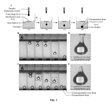
[0056] FIG. 1 depicts a process leading to liquid-liquid encapsulation
and visual
characterization of encapsulation layer. (A) Step-by-step schematic
representation (not to
scale) of the encapsulation process. (B) Time series demonstrating interfacial
phenomena of
entry of a core droplet (consisting of liquid L1, here laser oil) inside
liquid bath L3 (here water)
when there was no interfacial film (or layer) (i.e., absence of liquid L2) and
therefore no
encapsulation. Here impact height, H = 6.5 cm (C) Time series illustrating
encapsulation
process in the same experimental set up as (B) after a thin interfacial film
(or layer) (here L2
was canola oil) of volume Vfilm = 350 pL has been dispensed on top of the host
water bath. The
fourth time stamp denotes successful shell formation and therefore completion
of
encapsulation process, with the required time being 42.97 ms. (D) Zoomed in
view of the
formation process of the shell layer (made of the interfacial liquid L2), the
region of interest is
- 13-
CA 03131030 2021-08-20
WO 2020/168432 PCT/CA2020/050222
highlighted on the corresponding time snap T = 24.22 ms in time series (C) by
a dotted square..
(E) Zoomed in view of an encapsulated drop corresponding to the region of
interest highlighted
by another dotted square on time snap T = 47.66 ms in (C), with distinctively
identifiable
outlines of the core and shell. The scale bar represents 4 mm wherever
applicable throughout
the figure.
[0057] FIG. 2 depicts dye assisted visualization of encapsulation
process: (A, D)
represent grayscale images of settled unencapsulated and encapsulated drops
respectively
captured using high speed camera. (B, E) provides another visualization of the
unencapsulated
and encapsulated drops respectively captured using a digital SLR camera from a
plane
perpendicular to that of high-speed camera. (C, F) represents the extracted
drop shape (using
image processing) and volume calculation using vertical stack of cylinders
with varying radius
at pixel level resolution for the unencapsulated and encapsulated drops
respectively. For the
encapsulation experiment reported herein, the interfacial film volume
(consisting of dyed
canola oil suspension), Vfiim is 150 pL and the impact height, H is 8 cm.
[0058] FIG. 3 depicts success of encapsulation: dependence on impact
Weber
number, We and non-dimensionalized interfacial film volume, \him/Wore. (A)
Successful
encapsulation: Time series depicting successful encapsulation process for We =
130 and
Vfilm/Vcore = 87.92. (B) No encapsulation: Time series demonstrating the
unsuccessful attempt
of the droplet towards encapsulation and consequent entrapment at the
interfacial layer for the
same impact Weber number, We = 130 but an increased interfacial film volume
with Vfilm/Vcore
= 91.74. (C) A regime map demonstrating the dependence of the success of
encapsulation
process on Wei and Vfilm/Vcore. The experimental threshold for the same is
illustrated by the
zone boundary separating the two regimes - successful encapsulation and no
encapsulation.
[0059] FIG. 4 depicts stability and integrity of encapsulation and
dependence of extent
of encapsulation on interfacial film volume. (A) Wetting signature of core
liquid (laser oil), shell
liquid (canola oil) and the encapsulated drop on PMMA substrate. The inset
provides
equilibrium shapes and the corresponding contact angle values of the
encapsulated drop after
it was allowed to settle for 5 minutes, 20 minutes, 2 hours and overnight. (B)
a visual
comparison between the fluorescent signatures of the encapsulated and
unencapsulated drop
at an excitation wavelength of 365 nm. An oil soluble fluorescent dye was
mixed with the
interfacial liquid to aid visualization (see section S5 and Figure 10 in the
Example 2 for further
details). The difference in contact angle between two drops also was readily
identifiable. (C)
Quantification of the extent of encapsulation with change in the volume of
interfacial layer:
- 14 -
CA 03131030 2021-08-20
WO 2020/168432 PCT/CA2020/050222
Dependence of encapsulated/settled drop volume, theoretically estimated
encapsulated film
thickness, encapsulation/penetration time and contact angle (on PMMA) on
interfacial film
volume. The calculated shell thickness is plotted in a semi-log scale in the
right Y axis, while
the rest are represented in linear scale on the left Y axis. The inset
demonstrates the variation
in core drop volume and the corresponding encapsulated shell volume with
interfacial film
volume. (D) Equilibrium outlines of encapsulated drops for different
interfacial film volume. The
scale bar represents 0.75 mm wherever applicable throughout the figure.
[0060] FIG. 5 depicts evaluation of potential of the herein described
method in
safeguarding the core drop from an aggressive (miscible) environment. (A) Time
series
illustrating the water entry of an ethylene glycol drop. Due to its
miscibility in water, the drop
gets dissolved in the surrounding medium upon its entrance. (B) Time series
demonstrating
the water entry of another ethylene glycol drop of same volume - this time the
droplet passed
through an interfacial layer of canola oil (\him = 220pL) before it entered
the water bath. (C)
Post-encapsulation top-view of the interfacial canola layer. (D) Bottom view
of the
encapsulated drop captured via bright-field optical microscopy. If not
explicitly mentioned
otherwise, the scale bar represents 4 mm wherever applicable.
[0061] FIG. 6 depicts encapsulation with stratified intermediate liquid
column instead
of a thin interfacial film: (A) Schematic representation (not to scale) of the
encapsulation
process in presence of two stratified liquid columns, (B) A typical
encapsulation experiment
(represented in the form of a time series) demonstrating the journey of a core
laser oil droplet
through a stratified hexane layer (nominal height H2 = 5 cm) stacked on top of
a water bath
(nominal height H1 = 10 cm) for an impact height H = 6 cm. The drop is seen to
get
encapsulated with hexane at the hexane-water interface. The wrapping layer can
be
distinctively noticed in the time stamps corresponding to T = 104.69 ms and T
= 1800.16 ms.
[0062] FIG. 7 depicts shape of interfacial layer ¨ (A) Schematic
representation (not
to scale) of the canola lens floating on top of a water bath, (B) grayscale
experimental
image of the interfacial layer captured with a high-speed camera after 220 pL
of canola oil
dispensed on top of a water bath (4 mm scale bar) (C) image of the interfacial
layer in
same experimental set up captured using a digital SLR camera from a plane
perpendicular
to that of the high-speed camera.
[0063] FIG. 8 depicts a schematic representation (not to scale) of the 2-D
projection of
an axis-symmetric encapsulated drop with uniform shell thickness.
- 15-
CA 03131030 2021-08-20
WO 2020/168432 PCT/CA2020/050222
[0064] FIG. 9 depicts a schematic illustration (not to scale) of the
criteria for the
formation and stability of the encapsulated state: (A) Formation of an
encapsulated drop is
thermodynamically feasible when the Gibbs free energy change during the
transition from state
(a) to (b) is negative. A zoomed in view of the encapsulated drop is provided
in (c) with relevant
geometric parameters used in the calculation of free energy change. (B) The
encapsulated
drop remains stable upon formation if the transition from state (a) to state
(b) is
thermodynamically unfavorable i.e. has an associated positive free energy
change.
[0065] FIG. 10 depicts a fluorescent characterization of the encapsulation
layer:
Fluorescent signature of (A) laser oil and dyed canola oil drop, (B)
encapsulated and
unencapsulated drops inside host water bath upon being excited with 365 nm
ultraviolet
source.
[0066] FIG. 11 depicts a schematic representation (not to scale) of the
wetting situation
assuming formation of a hypothesized thin water film (adopted from (6)). yi
refers to the
interfacial tension between phase i and j, where (i,j) E{s,w,o}. Here s
represents the solid
substrate and w denotes the surrounding water medium while o stands for the
oil droplet.
[0067] FIG. 12 depicts a cross-sectional view of the geometric profile of
the interfacial
oil layer ¨ Representation of a liquid lens as an intersection of two spheres
with different radii
at a common circular plane.
[0068] FIG. 13 depicts a theoretical estimation of viscous dissipation
during a drop's
downward motion through an interfacial layer: (A) Schematic (not to scale)
representation of
the simplified framework for estimation of viscous dissipation. (B)
Theoretical dependence of
the viscous dissipation and the impact kinetic energy on the radius of the
core drop. Here H =
6.5 cm and Omax = 2.65 mm. Minimum drop volume (theoretical) for successful
encapsulation
is found to be 4.5 pL.
[0069] FIG. 14 depicts (C) a regime map demonstrating dependence of the
success of
encapsulation process on We, and Omax/(2Rc). The experimental threshold for
the same is
illustrated by the zone boundary separating the two regimes ¨ successful
encapsulation and
no encapsulation. The scale bar represents 4 mm wherever applicable throughout
the figure.
DETAILED DESCRIPTION
[0070] Generally, the present disclosure relates to liquid encapsulation
methods,
encapsulated core materials produced by these methods, and uses of the
encapsulated core
- 16 -
CA 03131030 2021-08-20
WO 2020/168432 PCT/CA2020/050222
materials. By liquid encapsulation, it is meant that a core material, such as
a liquid, solid or
semi-solid core material, is encapsulated in a liquid shell. This is
accomplished, in general, by
providing an interfacial fluid that acts as a barrier between the core
material and a host fluid
and passing the core material through the interfacial layer and into the host
fluid. The core
material is imparted with sufficient energy, e.g. kinetic energy or force, to
pass through the
interfacial fluid and into the host fluid. As the core material moves into the
host fluid, a shell
comprised of interfacial fluid is formed around the core material. This
results in the formation
of an encapsulated core material in the host fluid. The encapsulated core
material may remain
in the host fluid for use, or may be subjected to further treatment steps
prior to use. A skilled
person will appreciate that the liquid encapsulation methods of the present
disclosure, and the
products produced thereby, have many practical applications, including but not
limited to
carrying and/or delivering an additive of interest, such as an active
ingredient or payload.
[0071] In an aspect of the present disclosure, there is provided a method
of forming an
encapsulated core material, i.e. a liquid-encapsulated core material. The
method comprises
providing an interfacial fluid and a host fluid. The interfacial fluid is
provided between the core
material and the host fluid. It will be noted that the terms liquid and fluid
are used substantially
interchangeably herein to refer to flowable materials. The term material is
used substantially
interchangeably with substance or composition in that a material may comprise
one or more
components. The interfacial fluid and the host fluid are selected relative to
each other such
that the interfacial fluid is capable of being layered on the host fluid. Any
suitable means of
layering may be utilized. Layering may occur naturally due to the
physicochemical properties
of the interfacial fluid and the host fluid and/or may be facilitated through
layering techniques
know to those skilled in the art. In accordance with embodiments of the
disclosure, a selected
core material is passed through the interfacial fluid with sufficient energy
to enter into the host
fluid. The core material and the interfacial fluid are selected relative to
each other such that,
as the core material passes through the interfacial fluid and into the host
fluid, the interfacial
fluid forms a liquid shell around the core material, thereby encapsulating the
core material to
form an encapsulated core material, e.g. a liquid-encapsulated core material,
in the host fluid.
The host fluid may comprise one or multiple units of the encapsulated core
material. The
encapsulated core material may take on any suitable size or shape in the host
fluid, such as a
substantially spherical shape.
[0072] The interfacial layer may itself comprise one or more layers.
Thus, in certain
embodiments, there is provided a method of forming a multi-layered
encapsulated core
- 17-
CA 03131030 2021-08-20
WO 2020/168432 PCT/CA2020/050222
material comprising a core material and a shell, the method comprising:
providing an interfacial
fluid layer and a host fluid, the interfacial fluid layer comprising at least
a first and a second
interfacial fluid, the first interfacial fluid being layered on the second
interfacial fluid and the
second interfacial fluid being layered on the host fluid; and passing a core
material having
sufficient kinetic energy through the interfacial fluid layer and into the
host fluid such that the
interfacial fluid layer forms a shell around the core material, the shell
comprising the at least
first and second interfacial fluid, thereby forming the multi-layered
encapsulated core material.
[0073] In another an aspect of the disclosure, there is provided an
encapsulated core
material formed via any one of the methods described throughout the
specification, including
the examples. The encapsulated core material may be present in the host fluid
or may be
subjected to further manipulation prior to use. In some embodiments, the
encapsulated core
material may be isolated, or transferred from the host fluid, utilizing
techniques known to those
of skill in the art. For example, the encapsulated core material may be
transferred from a first
host fluid to a second host fluid prior to use, or may be subjected to further
process steps, such
as isolation, drying, freezing, freeze-drying, functionalization, or labeling,
to name but a few.
[0074] In another aspect, there is provided an encapsulated core material
composition.
In some embodiments, the encapsulated core material composition comprises an
encapsulated core material, the encapsulated core material comprising a core
material and an
interfacial fluid, the interfacial fluid encapsulating the core material, e.g.
forming a shell. In
some embodiments, the encapsulated core material is present in a host fluid.
In some
embodiments, the encapsulated core material is isolated from the host fluid.
In some
embodiments, the encapsulated core material composition comprises a host
fluid; and an
encapsulated core material in the host fluid, the encapsulated core material
comprising a core
material and an interfacial fluid, the interfacial fluid encapsulating the
core material (e.g.
forming a shell around the core material).
[0075] As used herein, sufficient kinetic energy refers to the core
material having
sufficient energy (e.g. combination of velocity, mass, density, etc.), to pass
through the
interfacial fluid into the host fluid. Energy may be imparted onto the core
material by any
suitable means or force, including but not limited to gravity. The amount of
kinetic energy
required for a particular core material to pass through the interfacial fluid
and into the host fluid
will depend on a number of factors and can be determined by persons of skill
in the art and
having regard to the present disclosure. Factors to consider may include but
are not limited to
one or combination of: (i) composition, size, mass, shape, viscosity, velocity
and/or density of
- 18-
CA 03131030 2021-08-20
WO 2020/168432 PCT/CA2020/050222
the core material; (ii) composition, density and/or viscosity of the
interfacial fluid; or (iii)
thickness and/or interfacial energies of the interfacial layer; which are
properties that may be
known or determined for a particular core material and interfacial fluid
(e.g., see Example 1
(for example, Sections - Theoretical criteria governing the formation and
stability of
encapsulation: an equilibrium thermodynamics perspective; and Role of impact
Weber number
and interfacial film (or layer) volume on successful encapsulation: deviation
from idealized
theoretical estimate), Fig. 3, Fig. 14, etc.); and (iv) composition, density
and/or viscosity of the
host fluid. Thus, sufficient kinetic energy may be determined by a person of
skill in the art
depending at least on the known or determined properties of the selected core
material,
interfacial fluid and/or host fluid, their relation to one another, and/or the
method steps
employed.
[0076] A suitable combination of core material, interfacial fluid and host
fluid may be
selected by a person of skill in the art depending on the particular objective
and application. A
skilled person, having regard to the present disclosure, will understand that
the relative
properties of the core material, the interfacial fluid and the host fluid must
be considered in
selecting a combination that will result in a desired rate of successful
encapsulation. As used
herein, physicochemically compatible refers to relative properties of two
materials in
communication with one another (e.g. the core material and the interfacial
fluid and/or the
interfacial fluid and the host fluid) that permit encapsulation of the core
material according to
the disclosed methods. For example, two physicochemically compatible materials
in
communication may be mutually unreactive and/or immiscible. In some
embodiments, the core
material and the interfacial fluid are physicochemically compatible. In some
embodiments, the
interfacial fluid and host fluid are physicochemically compatible. In some
embodiments, the
host fluid and core material are physicochemically compatible. In some
embodiments, which
may be combined with any of the embodiments described herein, the host fluid
and the core
material are not physicochemically compatible (i.e. are physicochemically
incompatible) in the
context of the present disclosure, e.g. they are reactive and/or are miscible
relative to one
another. "Miscible" or "miscibility" refers to a property of two liquids that
when mixed provide a
homogeneous solution, or a single phase. In contrast, "immiscible" or
"immiscibility" is a
property of two liquids that when mixed provide a heterogeneous mixture, or
two distinct
phases (i.e., layers). As a skilled person would recognize, this is not meant
to imply that
combinations of the two liquids will be single-phase mixtures when "miscible",
or two-phase
mixtures when "immiscible" in all proportions or under all conditions.
- 19-
CA 03131030 2021-08-20
WO 2020/168432 PCT/CA2020/050222
[0077] In embodiments any of the methods and compositions described herein,
any one or
more of the host fluid, interfacial fluid, and core material may be an aqueous
fluid, a non-
aqueous fluid, a polymeric fluid, a hydrophilic fluid, a hydrophobic fluid or
an amphiphilic fluid.
When comparing two materials to each other, they may be described, for
example, as relatively
more or less hydrophobic or hydrophilic when compared to a reference fluid. In
some
embodiments, the host fluid and the core material are a different fluid. In
some embodiments,
the host fluid and the core material are the same fluid. In other embodiments,
the core material
may be a solid or semi-solid, and that solid or semi-solid may be hydrophilic,
or hydrophobic.
In some embodiments, the core material is physicochemically incompatible with
the host fluid.
In some embodiments, the host fluid comprises an aqueous fluid, the
interfacial fluid comprises
a non-aqueous fluid, and the core material is physicochemically incompatible
with the host
fluid. In some embodiments, the host fluid comprises a non-aqueous fluid, the
interfacial fluid
comprises an aqueous fluid, and the core material is physicochemically
incompatible with the
host fluid. In some embodiments, the host fluid comprises a hydrophilic fluid,
the interfacial
fluid comprises a hydrophobic fluid, and the core material is
physicochemically incompatible
with the host fluid. In some embodiments, the host fluid comprises a
hydrophobic fluid, the
interfacial fluid comprises a hydrophilic fluid, and the core material is
physicochemically
incompatible with the host fluid. In some embodiments, the core material is
physicochemically
compatible with the host fluid but encapsulation is nonetheless desired.
[0078] In some embodiments of the methods and compositions described
herein, the
core material has a density pi, the interfacial fluid has a density p2, the
host fluid has a density
P3 . In some embodiments, p2 < p3 < pi. In some embodiments, pi > P2> p3 .
Further, the
interfacial fluid is capable of being layered on the host fluid. In some
examples, the interfacial
fluid is layered on the host fluid, for example, by providing a volume V of
the interfacial fluid,
which is selected to provide the interfacial fluid layered on the host fluid.
Said layering may be
facilitated due to a difference in hydrophilic/hydrophobic properties of the
host fluid and
interfacial fluid, a difference in miscibilities of the host fluid and
interfacial fluid, a difference in
densities, or a difference in surface tensions. In some examples, the
interfacial fluid may be
layered on the host fluid because the interfacial fluid is hydrophilic and the
host liquid is
hydrophobic, or vice versa. Alternatively, the interfacial fluid may be
layered on the host fluid
because the interfacial fluid and the host liquid are immiscible. In other
examples, the interfacial
fluid may be layered on the host fluid because the interfacial fluid is less
dense than the host
liquid. For sufficiently small volumes V of the interfacial fluid, the
interfacial fluid may be layered
- 20 -
CA 03131030 2021-08-20
WO 2020/168432 PCT/CA2020/050222
on the host fluid even if the density of the interfacial fluid is greater than
the density of the host
fluid. For example, if a heavier fluid is dispensed on top of a lighter fluid
at a very slow flow rate
and from close vicinity (so that kinetic energy at point of contact is
minimal), then it can be
possible to stably hold a heavier fluid atop a lighter fluid (e.g., by relying
on surface tensions).
However, for higher volumes V, the interfacial fluid may destabilize and sink;
and as such,
encapsulation with heavier interfacial fluids is possible if the volume V is
sufficiently low. A
skilled person would appreciate that the volumes that are necessary to
facilitate layering
depends on the types of interfacial and host fluids that are being used.
[0079] In some examples, the interfacial fluid is layered on the host
fluid by dispensing
the interfacial fluid on top of the host fluid, wherein dispensing comprises
using a syringe pump
and needle assembly, a rotary, a piezoelectric dispenser, or an electrical
actuator to dispense
the interfacial fluid on top of the host fluid.
[0080] When forming an encapsulated core material, the volume V of
interfacial fluid
that facilitates a successful encapsulation is, at least in part, dependent on
the end use or
specific application of the encapsulated material. As is described herein,
providing a larger
volume V of the interfacial fluid can increase the thickness of the shell that
forms around the
core material as it is being encapsulated. As will be appreciated by skilled
persons, increasing
the volume V, may require increasing the amount of kinetic energy that a core
material has
such that it can successfully pass through the layer of interfacial fluid into
the host fluid to be
encapsulated (as described above). For example, if V1 > V2, then the thickness
of the shell
encapsulating the core material resulting from V1 will be greater than the
thickness of the shell
encapsulating the core material resulting from V2; and the kinetic energy
needed to pass the
core material through volume V1 of interfacial fluid will be greater than the
kinetic energy
needed to pass the core material through volume V2 of interfacial fluid (e.g.,
see Example 1,
Section - Confirmation of stability and integrity of encapsulation & the
dependence on
interfacial film volume; Figure 4).
[0081] Optimal ranges of volume V may be selected by a person of skill in
the art
depending on the desired application or end use of the encapsulated material.
In some
examples, volume V is in a range of about 0.1 mL to about 10 mL; or in a range
of 0.1 mL to
about 100 mL. Smaller or larger volumes are of course possible and can be
suitably selected
by persons of skill in the art depending on the application, objective and
scale.
[0082] The shell of the encapsulated core material has a thickness T and
modifying
the volume V adjusts said thickness. For example, the thickness of the shell
of the
- 21 -
CA 03131030 2021-08-20
WO 2020/168432 PCT/CA2020/050222
encapsulated core material can be tuned, or varied by changing the thickness
of the layer of
interfacial fluid prior to passing the core material therethrough. As
described above, providing
a larger volume V of the interfacial fluid can increase the thickness T of the
shell that forms
around the core material. For example, if volume V1 of the interfacial fluid
provides a thickness
T1 of the shell encapsulating the core material, than increasing V1 to V2
(where V1 <'12) will
increase the thickness T1 to T2 (where T1 <T2). For further example, changing
the volume of
the interfacial layer may form an encapsulated core material where the shell
layer accounts for
more than 50% of the volume of the encapsulated core material. Optimal ranges
of thickness
T may be selected by a person of skill in the art depending on the desired
application or end
use of the encapsulated material, by changing the thickness of the layer of
interfacial fluid. In
some examples, the relationship of modifying the volume V to adjust the
thickness T is a non-
linear relationship.
[0083] As described above, the core material may be a fluid. Any suitable
fluid may be
used. A skilled person will be able to select a suitable fluid depending on
the particular
application and any additives to be included in the core fluid, and the
particular composition of
the interfacial fluid and the host fluid. When the core material is a fluid,
the core material may
be formed as a core droplet. A droplet may be formed by any suitable means
known in the art.
In some examples, forming the core droplet comprises dispensing fluid from a
syringe pump
and needle assembly, a rotary, or an electrical actuator.
[0084] In some embodiments of the methods described herein, passing the
core
material through the interfacial layer comprises dropping the core material
from a suitable
height H from the interfacial fluid. The force of gravity will cause the
dropped core material to
accelerate toward the interfacial layer thereby imparting a kinetic energy to
the dropped core
material. Particularly, dropping the core material comprises imparting a first
kinetic energy We,
to the core material. If the spatial relationship between the core material
and the interfacial fluid
is other than vertical, then height H may be replaced with distance D or
another suitable unit
of measurement and another force can be used to impart kinetic energy onto the
core material.
[0085] A skilled person will be able to determine a suitable height H from
which to drop
a core material in order to ensure a desired level of encapsulation success.
In some examples,
a condition for formation of an encapsulated core material for an impact
height H is based on
the following equation:
- 22 -
CA 03131030 2021-08-20
WO 2020/168432 PCT/CA2020/050222
H> 3012 + 723 - 71)
pig&
where H is impact height, g is gravitational acceleration, Rc is radius of the
core material
assuming spherical geometry, pi is density of the core material, y12 is core
material /interfacial
fluid interfacial tension, y23 is interfacial fluid /host fluid interfacial
tension, and Vi is air/core
material interfacial tension.
[0086] In some examples, the core droplet gains a kinetic energy
(manifested in the
form of impact Weber number We,), based on the following equation:
We ¨ piv21,
i
71
where v is velocity of the core material immediately before impacting the
interfacial fluid, g is
acceleration due to gravity I, is characteristic length scale typically
expressed as radius of the
core material assuming spherical shape, H is impact height, Vi is air/core
material interfacial
tension, and pi is density of the core material.
[0087] As described above, in some examples, passing the core material
through the
interfacial fluid comprises actuating the core material from a distance D from
the interfacial
fluid, comprising imparting a second kinetic energy We, to the core material.
The core droplet
may be accelerated by any suitable means known in the art, such as but not
limited to using
pressure, jetting, electrostatic interactions, electrohydrodynamic actuation,
or a centripetal
force. For example, an adverse viscous energy barrier to encapsulation of a
core material may
be mitigated by suitably compensating the kinetic energy of a core droplet
(e.g. by increasing
impact height or by providing acceleration by other means ¨
jetting/electrohydrodynamic
actuation).
[0088] As described above, the core material may be a solid. A skilled
person will be
able to select a suitable solid depending on the particular application and
any additives to be
included in the core material, and the particular composition of the
interfacial fluid and the host
fluid. When the core material is a solid, the core material may be a core
solid.
[0089] In some embodiments of the methods described herein, when passing
the core
material through the interfacial fluid, the only fluid the core material may
contact is the
interfacial fluid. In some embodiments of the methods described herein,
forming the
encapsulated core material comprises protecting the core material with the
shell. In such a
- 23 -
SUBSTITUTE SHEET (RULE 26)
CA 03131030 2021-08-20
WO 2020/168432 PCT/CA2020/050222
case, the interfacial fluid provides a barrier between the core material and
the host fluid. In
some examples, protecting the core material comprises preventing the core
material from
contacting the host fluid. This may be because the core material and the host
fluid are
incompatible; for example, because the core material is miscible with the host
fluid, or because
the core material is reactive with the host fluid, or is otherwise degradable
in the host fluid.
[0090] In some embodiments of the methods and compositions described
herein, one
or more of the core material, the interfacial fluid, and the host fluid
comprises an additive. As
used herein, "additive" refers broadly to any compound, mixture of compounds,
component, or
mixture of components provided in any one or more of the core material, the
interfacial fluid,
and the host fluid. The additive may be active, reactive or inert. An additive
may, for example,
refer to an active additive, such as a pharmaceutical compound/active
pharmaceutical
ingredient (API), a reactive additive, such as a reactive chemical species, or
an inert additive,
such an inert excipient. These are just a few examples and should not be
viewed as limiting in
any way. Additives may be comprised in any one or combination of the core
material, interfacial
fluid, or host fluid for any suitable purpose.
[0091] The methods and compositions of the present disclosure may be
used, for
example, to faciliate: (i) carrying and/or delivering and/ releasing (e.g.,
via delayed release,
controlled release, quick release, etc.) of an active ingredient to or at
intended site, e.g., within
the body of a subject (blood stream, gastrointestinal tract, etc.), within
soil, within water, within
a food or beverage product, within an agricultural product, within a cosmetic
product, within a
consumer product, a perfume product, etc.); and/or (ii) protecting a reactive
or degradable
ingredient the final, encapsulated core material from a hostile environment or
hostile conditions
that would otherwise degrade, dissolve, alter, or react with said compound,
mixture of
compounds, component, or mixture of components - for example, until said
compound, mixture
of compounds, component, or mixture of components can be delivered to their
intended site
or used for their intended purpose.
[0092] In some non-limiting examples, the additive is a pharmaceutical
compound, an
excipient, a food or beverage ingredient (e.g., caffeine, vitamin, nutrient,
etc.), a cannabinoid
(e.g., tetrahydrocannabinol, cannabidiol), an aroma compound, an enzyme, a
microparticle, a
nanoparticle, a surfactant, a mineral, a salt, an oil (e.g., a fish oil), a
probiotic, a polymer, a
water-treatment compound, or a soil-treatment compound. In some examples, the
additive is
disposed in a fluid phase (e.g., the core material, interfacial fluid, and
host fluid are all fluids)
to facilitate absorption into a subject's blood stream; or to facilitate
biodegradability.
- 24 -
CA 03131030 2021-08-20
WO 2020/168432 PCT/CA2020/050222
[0093] Care should be taken when deciding the concentration of the
additive to ensure
that the volume and/or density of the resulting mixture/suspension still meets
the criteria
wherein the core material can be successfully encapsulated. If necessary,
parameters of the
core, interfacial layer and/or host fluid may be suitably adjusted to account
for the presence of
additive. The kinetic energy of the core material (e.g., impact height) and/or
interfacial layer
volume may also be adjusted to ensure successful encapsulation.
[0094] In some embodiments of the methods and compositions described
herein, the
encapsulated core material comprises a condensed phase, such as a liquid,
solid, or a
combination thereof. When the core material is a liquid, any suitable liquid
may be used. A
skilled person will be able to select a suitable fluid depending on the
particular application and
any additives to be included in the core fluid, and the particular composition
of the interfacial
fluid and the host fluid. In some examples, the liquid may include, but is not
limited to a liquid
mixture, a solution, a suspension, a liquid polymer, or a liquid polymer
mixture. For example,
when the core material is a fluid, the fluid may comprise any one or a
combination of: a solid
suspension, an additive, a microparticle, microparticles, a nanoparticle,
nanoparticles, a
surfactant, food nutrients, an Omega oil, a fish oil, a probiotic, or a
polymer. In some examples,
the fluid a laser liquid. In some examples, the laser liquid is a mixture of
silicanes and
polyphenol ethers. When the core material is a solid, the solid may be a
polymer, a nut, or a
seed.
[0095] In embodiments of the methods and compositions described herein,
the
interfacial fluid is a fluid. Any suitable fluid may be used. A skilled person
will be able to select
a suitable fluid depending on the particular application and any additives to
be included in the
interfacial fluid, and the particular composition of the core fluid and the
host fluid. In some
examples, the liquid may include, but is not limited to a liquid mixture, an
oil, a solution, a
suspension, a liquid polymer, a liquid polymer mixture, a liquid agar gel, a
liquid gelatin, or a
liquid cellulose. In some examples, the interfacial fluid is a canola oil, a
silicone oil,
hydroxypropylmethylcellulose, or hexanes. In some embodiments of embodiments
the
methods and compositions described herein, the interfacial fluid has an
interfacial energy
suitable for encapsulating a core material.
[0096] In embodiments of the method and compositions described herein,
the host
fluid is a fluid. Any suitable fluid may be used. A skilled person will be
able to select a suitable
fluid depending on the particular application and any additives to be included
in the host fluid,
and the particular composition of the core fluid and the interfacial fluid. In
some examples, the
- 25 -
CA 03131030 2021-08-20
WO 2020/168432 PCT/CA2020/050222
liquid may include, but is not limited to a liquid mixture, a solution, a
suspension, a liquid
polymer, a liquid polymer mixture, a liquid agar gel, a liquid gelatin, or a
liquid cellulose. In
some examples, the host fluid is an aqueous liquid, such as water.
[0097] In certain embodiments of the method described herein, forming the
encapsulated core material may further comprise hardening the core material or
the shell. In
some examples, hardening the core material or the shell comprises curing the
core material to
form a hardened core material, or curing the shell to form a hardened shell.
In such examples,
the core material may comprise for example an UV-curable epoxy resin, a
biocompatible
photopolymer, or a resin-based composite (e.g., a dental composite resin). In
some examples,
curing the shell comprises exposing the shell to ultraviolet radiation. In
such examples, the
shell may comprise an UV-curable epoxy resin, a biocompatible photopolymer, or
a resin-
based composite (e.g., a dental composite resin). In other examples, curing
the shell
comprises triggering a coacervate formation; or comprises exposing the shell
to heat.
[0098] Certain embodiments of the methods described herein may further
comprise
enclosing the encapsulated core material. As used herein, enclosing refers to
further
encapsulating the already encapsulated core material with an additional layer
of material (e.g.,
an enveloping layer). In some examples, enclosing the encapsulated core
material comprises
enclosing the encapsulated core material with a polymer sheet or an
interfacial assembly of
particles (e.g., the enveloping layer). Any suitable polymer sheet or an
interfacial assembly of
particles may be used. A skilled person will be able to select a suitable
polymer sheet or an
interfacial assembly of particles depending on the particular application and
any additives to
be included in the encapsulated core material, and the particular composition
of the
encapsulated core material. In examples wherein the encapsulated core material
is enclosed
with a polymer sheet, the polymer sheet may comprise a soft gelatin sheet, or
polystyrene
films.
[0099] In respect of the compositions described herein, a condition for
stability of an
encapsulated core material in the host fluid is based on the following
equation:
Y13 Y12 + Y23
where y13 is core material/host fluid interfacial tension, y12 is core
material /interfacial fluid
interfacial tension, and y23 is interfacial fluid/host fluid interfacial
tension.
[00100] In some embodiments the compositions described herein, the shell
is a
hardened shell. In some examples, the hardened shell comprises a cross-linked
interfacial
- 26 -
CA 03131030 2021-08-20
WO 2020/168432 PCT/CA2020/050222
fluid. In such examples, the shell may comprise a cross-linked epoxy resin,
biocompatible
photopolymer, or resin-based composite (e.g., a dental composite resin). In
other examples,
the hardened shell comprises a coacervate formation formed from the
interfacial fluid.
[00101] In certain embodiments of the method compositions described herein
may
further comprise an enveloping layer enclosing the encapsulated core material,
where
enclosing refers to further encapsulating the already encapsulated core
material with the
enveloping layer. The enveloping layer may comprise a polymer sheet or an
interfacial
assembly of particles. Any suitable polymer sheet or an interfacial assembly
of particles may
be used. A skilled person will be able to select a suitable polymer sheet or
an interfacial
assembly of particles depending on the particular application and any
additives to be included
in the encapsulated core material, and the particular composition of the
encapsulated core
material. In examples wherein the encapsulated core material is enclosed with
a polymer
sheet, the polymer sheet may comprise a soft gelatin sheet, or polystyrene
films.
[00102] In some embodiments of the compositions as described herein, the
shell may
comprise at least a first and a second interfacial fluid, and the core
material is encapsulated
with a first shell formed from the first interfacial fluid, and the first
shell is encapsulated with a
second shell formed from the second interfacial fluid.
[00103] In another aspect of the disclosure, there is provided an
encapsulated core
material prepared by any one of the methods described herein. In some
examples, said
encapsulated core material is present (e.g. dispersed or suspended) in a host
fluid.
[00104] In some embodiments of the methods, compositions, and encapsulated
core
materials as described herein, the encapsulated core material does not
comprise emulsions,
such as double emulsions or multiple emulsions. In some embodiments of the
methods,
compositions, and encapsulated core materials as described herein, the
encapsulated core
material is not prepared via a jet breakup mechanism; and/or, encapsulation of
the core
material does not occur via a jet breakup mechanism. In some embodiments of
the methods,
compositions, and encapsulated core materials as described herein, the
encapsulated core
material is not prepared via a microfluidic device; and/or, encapsulation of
the core material
does not involve a microfluidic device.
[00105] In another aspect, there is provided a use of the encapsulated
core material
made by the methods described herein, or the compositions described herein. In
some
embodiments, the compositions are for use carrying, delivering and/or
releasing an active
ingredient. In some embodiments, the active ingredient is a food or drug
ingredient, such as a
- 27 -
CA 03131030 2021-08-20
WO 2020/168432 PCT/CA2020/050222
pharmaceutical compound. Further described herein is a use of the encapsulated
core material
made by the methods described herein, or the compositions described herein for
sustained or
delayed release of an active ingredient, such as a pharmaceutical compound. In
some
examples, there the encapsulated core material is used for controlled release
of an additive,
such as a pharmaceutical compound, or for quick release of a pharmaceutical
compound. In
another aspect, there is provided a pharmaceutical composition comprising a
liquid-
encapsulated core material comprising at least one active pharmaceutical
ingredient; and a
pharmaceutically-acceptable excipient, carrier or diluent. In some
embodiments, the core
material is a carrier or diluent for the pharmaceutical ingredient. In some
embodiments, the
host fluid is the carrier for the liquid-encapsulated core material comprising
the at least one
active pharmaceutical ingredient. In accordance with embodiments of the
disclosure, the
pharmaceutical composition may be formulated for administration to a subject
by any suitable
means, for example, oral, parenteral, or topical administration. Parenteral
administration
bypasses the GI tract and includes, for example, intravenous, intramuscular,
intrathecal and
subcutaneous administration among others. The composition may be prepared in
any suitable
dosage form, such a solution, suspension, cream, gel, or ointment, among
others.
[00106] Also described herein is a use of the encapsulated core material
made by the
methods described herein, or the compositions described herein in a cosmetic
product. Further
described herein is a use of the encapsulated core material made by the
methods described
herein, or the compositions described herein for delayed release of an
additive in or from a
cosmetic product. In some examples, the encapsulated core material is used for
controlled
release of an additive in or from a cosmetic product, or for quick release of
an additive in or
from a cosmetic product. In some examples, the additive may comprise any one
or combination
of a time-release moisturizer, a time-release wrinkle smoother, a time-release
recovery cream,
or a time-release acne cleanser (with controlled release of salicylic acid).
[00107] In some embodiments as described herein is a use of the
encapsulated core
material made by the methods described herein, or the compositions described
herein, in an
emulsion or suspension.
[00108] Also described herein is a use of the encapsulated core material
made by the
methods described herein, or the compositions described herein for
encapsulating a food
product. Further described herein is a use of the encapsulated core material
made by the
methods described herein, or the compositions described herein in a food
product. In some
examples, the encapsulated core material is used for delayed release of an
additive from a
- 28 -
CA 03131030 2021-08-20
WO 2020/168432 PCT/CA2020/050222
food product; or for controlled release of an additive from a food product; or
for quick release
of an additive from a food product. In some examples, the additive comprises a
vitamin, an
enzyme, a nutraceutical, an oil (e.g., a fish oil), an omega fatty acid (e.g.,
omega 3 fatty acid),
caffeine, a cannabinoid (e.g., tetrahydrocannabinol, cannabidiol), or a
probiotic. In some
examples, the food product is a beverage, a nutraceutical, a confectionary, an
oil (e.g., a fish
oil), an omega fatty acid (e.g., omega 3 fatty acid), a seed, a nut, or a
probiotic. For example,
seeds or nuts may be a core material of an encapsulated core material, wherein
being
encapsulated by a shell of interfacial fluid protects the seed or nut from
oxidation.
[00109] Described herein is a kit comprising a host fluid, an interfacial
fluid, and a core,
and instructions for use thereof. The kit may further comprise an additive and
instructions for
adding the additive to any one of the core material, the interfacial fluid, or
the host fluid. Further
described herein is a kit comprising a host fluid, a encapsulated core
material in the host fluid,
and instructions for use thereof. The kit may further comprise an additive and
instructions for
adding the additive to any one of the encapsulated core material, or the host
fluid. In some
examples, the additive is a pharmaceutical compound, a food or beverage
ingredient (e.g.,
caffeine, vitamin, nutrient, etc.), an excipient, a cannabinoid (e.g.,
tetrahydrocannabinol,
cannabidiol), an aroma compound, an enzyme, a microparticle, a nanoparticle, a
surfactant, a
mineral, an oil (e.g., a fish oil), a probiotic, a polymer, a water-treatment
compound, or a soil-
treatment compound. In some examples, the additive is disposed in a fluid
phase (e.g., the
core material, interfacial fluid, and host fluid are all fluids) to facilitate
absorption into a subject's
blood stream; or to facilitate biodegradability.
[00110] Definitions
[00111] Unless defined otherwise, all technical and scientific terms used
herein have
the same meaning as commonly understood by one of ordinary skill in the art to
which this
invention belongs.
[00112] As used in the specification and claims, the singular forms "a",
"an" and "the"
include plural references unless the context clearly dictates otherwise.
[00113] The term "comprising" as used herein will be understood to mean
that the list
following is non-exhaustive and may or may not include any other additional
suitable items, for
example one or more further feature(s), component(s) and/or ingredient(s) as
appropriate.
[00114] The term "subject", as used herein, refers to an animal, and can
include, for
example, domesticated animals, such as cats, dogs, etc., livestock (e.g.,
cattle, horses, pigs,
sheep, goats, etc.), laboratory animals (e.g., mouse, rabbit, rat, guinea pig,
etc.), mammals,
- 29 -
CA 03131030 2021-08-20
WO 2020/168432 PCT/CA2020/050222
non-human mammals, primates, non-human primates, rodents, birds, reptiles,
amphibians,
fish, and any other animal. In a specific example, the subject is a human.
[00115] To gain a better understanding of the invention described herein,
the following
examples are set forth. It should be understood that these examples are for
illustrative
purposes only. Therefore, they should not limit the scope of this invention in
anyway. The
inventors do not wish to be bound by any scientific or mathematical theories
presented in the
specification or examples.
[00116] EXAMPLES
[00117] Example 1 - Encapsulation with an interfacial liquid layer: Robust
and
efficient liquid-liquid wrapping
[00118] Encapsulation enables isolation/protection and timely release of a
core additive.
Herein described is an efficient, robust method of encapsulation where a core
droplet is stably
wrapped by an interfacial liquid film (shell) upon being impinged on it from a
vertical separation.
A complex yet ultra-fast interplay between gravitational and interfacial
energies governs this
process. The volume of the interfacial layer and the kinetic energy of the
core droplet before
impact are identified to be the key control variables and their influence is
presented in a regime
map demarcating successful and unsuccessful encapsulation (e.g., see Fig. 3).
The practical
potential of the method is established by demonstrating its ability in
protecting a vulnerable
(miscible) core from an aggressive surrounding. With its robustness,
scalability, wide
operational spectrum, minimal restrictions on core-shell selection and
potential ability in
enhancing dosage efficiency and biocompatibility owing to a liquid wrapping
layer, the
proposed method suggests new pathways to stable liquid-based encapsulation.
[00119] More particularly, herein described is a method to achieve
encapsulation in an
ultra-fast, robust yet efficient manner utilizing a fundamental characteristic
of liquid, i.e.,
minimization of its interfacial energy. The herein described method is built
upon the
fundamentals of the impact driven water entry problem. A wide volume of
scientific endeavour
is dedicated to understanding the dynamics of impact of solid objects as well
as liquid droplets
on a liquid pool. The herein described method introduces an intermediate layer
in the traversal
path of the droplet and exploits the resulting complex interfacial dynamics
that leads to
formation of a stable and consistent liquid based wrapping layer.
[00120] Materials
- 30 -
CA 03131030 2021-08-20
WO 2020/168432 PCT/CA2020/050222
[00121] The
method involves three liquids, namely the core droplet (liquid 1, L1; core
material), the interfacial layer forming the shell (liquid 2, L2; interfacial
fluid) and the liquid bath
(liquid 3, L3; host fluid) that houses the encapsulated drop (encapsulated
cored material) after
it settles down. If not otherwise mentioned, a particular class of laser
liquid - a mixture of
silicanes and polyphenol ethers, with a water solubility of <0.1% (Product
Code: 57B63,
Cargille Laboratories Inc., Cedar Grove, NJ, USA) was used to form the core
droplet. Relevant
material properties were as follows: density pi = 1900 kg/m3, dynamic
viscosity pi = 1024 mPa-
s, liquid-air surface tension Vi = 50 mN/m, liquid-canola oil interfacial
tension yi2 = 2.22 mN/m
and liquid-water interfacial tension yi3 = 39.4 mN/m. The interfacial layer
that ultimately wraps
the core droplet was composed of canola oil (manufactured and marketed under
the brand
name of Clic International Inc., Ottawa, Canada), with density p2 = 913 kg/m3,
dynamic
viscosity 1.12 = 63.5 mPa-s, liquid-air surface tension y2 = 31.3 mN/m and
liquid-water interfacial
tension, y23 = 18.01 mN/m. The host liquid was chosen to be deionized water
(purified by Milli-
Q, MilliPoreSigma, Ontario, Canada) with density p3 = 1000 kg/m3, dynamic
viscosity p3 = 1
mPa-s and liquid-air surface tension y3 = 72 mN/m.
[00122] The
experiments were conducted in a distortion-free glass cuvette (Product
Code: SC-02, Kruss GmbH, Hamburg, Germany) of inner dimension 36 mm X 36 mm X
30 mm
with 2.5 mm wall thickness. The solid substrate used for studying the wetting
signature was
poly(methyl methacrylate) (PMMA). PMMA sheets of dimensions 150 mm X 150 mm
with
1 mm thickness (Plaskolite Inc., Columbus, Ohio, United States) were diced
into 25 mm X
25 mm square pieces for using as substrate material. For liquid dispensing
purposes, polished
and passivated stainless-steel needle tips with gauge 14 and inner diameter of
0.060" (Part
No. 7018035, Nordson EFD, East Province, RI, USA) were used.
[00123] To
render the interfacial layer optically opaque and ensure confirmatory visual
differentiation, the interfacial oil layer was mixed with a partially oil
soluble particle-based dye
(Product Name: OrcoSolve Quinoline, Organic Dyes and Pigments, Rhode Island,
RI, USA).
To ensure homogeneity, the prepared suspension was thoroughly mixed using a
vortex mixer
(Product catalog No. 02-215-422, Fisherbrand Pulsing Vortex Mixer, Fisher
Scientific, Ottawa,
Ontario, Canada) at 2700 rpm for 1 minute before conducting the experiments.
[00124] A
commercial oil soluble fluorescent dye (TP 3400, Tracer Product) was mixed
with the interfacial liquid L2 in 0.12% volume/volume ratio to aid visual
differentiation between
the encapsulated and unencapsulated drop. The surface tension values of the
interfacial oil
solution were confirmed to remain unaltered due to the addition of the dye.
- 31 -
CA 03131030 2021-08-20
WO 2020/168432 PCT/CA2020/050222
[00125] Method
[00126] For the herein described method, first, the cuvette was partially
filled with a
predetermined quantity of the host liquid (here with 24 ml of water). However,
minor variations
in the volume of the host liquid ( 2 ml) was seen to cause no noticeable
effect on the process
dynamics. A syringe pump and stainless-steel needle (disposable) assembly were
used
thereafter to dispense the interfacial liquid concentrically on the top of the
host liquid- air
interface. A slow and controlled liquid dispensation was used to prevent
disruption of the
interfacial layer due to sudden influx of the discharged liquid. The core
droplet was generated
thereafter at a slow and steady flow rate from a height H from the interface
(with H being the
vertical separation between the droplet and the canola-air interface) using
the same dispensing
system. Figure 1A depicts a step-wise schematic representation of the herein
described
method.
[00127] For a proof of concept, external actuation was not induced to
force drop
detachment from the needle. Consequently, the resulting droplet volume was
determined by
an interplay between the surface energy of the needle tip and effect of
gravity and therefore
remained invariant as long as the same class of needle tip and liquid
combination was used.
During the generation process, the core drop grew till a volume when the
surface tension forces
at the needle tip could no longer sustain its weight and it detached from the
needle tip thereafter
due to gravity. This volume was determined by the outer diameter of the
needle, the liquid-air
surface tension, and the effect of gravity. In the herein described
experiments, the average
nominal volume of the core Laser oil drop was found to be 15.5 pL with a
standard deviation
of 0.8 pL. Assuming spherical geometry, this average volume corresponded to a
radius of 1.54
mm, which was below the capillary length-scale. Precautions were taken while
choosing the
needle diameter, so that the size of the resulting core drop size was below
capillary length
scale, thereby eliminating unpredictable influences of gravitational forces on
the droplet
dynamics. However, it was found that there was no qualitative difference in
the encapsulation
process even if the drop radius was higher than the capillary length-scale.
Droplets with a
radius larger than the capillary length scale were successfully encapsulated
in a similar manner
implying that there was no fundamental restriction on the upper limit of
usable droplet volume
for the herein described method.
[00128] To eliminate unwanted movement of interfacial layer and consequent
loss of
concentricity in liquid dispensing during the experiments, usage of a stable,
horizontal,
vibration free platform was used. Any movement of the experimental set up was
minimized
- 32 -
CA 03131030 2021-08-20
WO 2020/168432 PCT/CA2020/050222
during the process, if not completely avoided. The experiments reported herein
were
performed on a vibration isolating optical table.
[00129] Results and Discussion
[00130] Experimental visualization of a typical encapsulation process
[00131] Atypical encapsulation process is illustrated in Figure 10-1E for
interfacial film
volume \him = 350 pL and impact height H = 6.5 cm. Upon detachment from the
dispensing
needle, the core droplet traversed through air before it comes in contact with
the interfacial
layer of L2. At the point of first contact with this interfacial layer, the
droplet possessed a kinetic
energy equal to the weight of the droplet multiplied by the impact height H
(assuming negligible
viscous dissipation in air). Upon contact the droplet attempted to penetrate
through this
intermediate layer. During its time of flight through interfacial layer, the
droplet undergoes a
complex non-trivial interaction where its kinetic energy facilitates the
formation of a secondary
wrapping layer of the interfacial liquid. Initially the droplet tried to drag
the interface downward
along it but after a while the interface attempted to retract back to its
original position. If the
droplet had sufficient kinetic energy, this competition lead to neck formation
and subsequent
separation of the droplet from the interface (as illustrated in the third time
stamp corresponding
to T = 24.22 ms in Figure 10).
[00132] Put another way, upon contact with the interfacial layer, the core
drop attempts
to penetrate through the intermediate layer. There are three competing effects
that govern the
penetration process. The core drop drags the L2 layer downward due to its
momentum, which
deforms the interface and increases its surface area. However, interfacial
forces acting on the
deformed L3-L2 and L2-L1 interfaces attempt to restore the interface back to
its original
position to minimize the interfacial energy. The viscous resistance of the
interfacial layer also
opposes the downward motion of the drop by dissipating its momentum. This
competition leads
to neck formation (time stamp T = 24.22 ms in Fig. 10). If the drop has
sufficient momentum
to overcome the barrier imposed by both the interfacial forces and the viscous
resistance, then
it can penetrate through the interfacial L2 layer, as is the case illustrated
in Fig. 10 (see the
time stamp T = 42.97 ms).
[00133] In the process the core drop detached a part of the film from the
interfacial
layer. This detached layer formed a thin enclosure (the encapsulating shell)
around the core
droplet. To elaborate this non-trivial interface evolution further, two
different stages of
encapsulation process has been zoomed in Figure 1D and 1E. Figure 1D
demonstrates the
necking process that lead to ultimate separation of droplet from interface,
while Figure 1E
- 33 -
CA 03131030 2021-08-20
WO 2020/168432 PCT/CA2020/050222
illustrates the enclosure formation around the core drop. In both the cases
the outlines of the
core drop and shell layer were distinctively visible and are highlighted for
clarity. Although
complex, this process was ultrafast with a typical successful encapsulation
requiring only tens
of milliseconds to complete.
[00134] Another consideration here was the equilibrium shape of the
interfacial layer
L2 that depended on the values of surface and interfacial tensions (manifested
in the spreading
parameter S = y3 ¨ y23 ¨ y2) and the dispensed volume. With S being positive,
canola drops
were seen to spread on top of the water-air interface as soon as they came in
contact with
water and ultimately formed a floating oil lens with one side in contact with
water while the
other side was exposed to air. Although from some experimental images, it
might appear that
there existed an intermediate water film preventing direct contact of the
canola lens with air,
the possibility of formation of such a pseudo-total wetting state has been
refuted both
theoretically and experimentally (see section Si and Figure 7 in Example 2).
[00135] The interfacial layer had the maximum film thickness at the centre
of the lens
and the geometric profile of the lens was symmetric about a vertical axis
passing through this
centre. It is desirable to map the output parameters (resulting shell
thickness, encapsulated
volume etc.) in terms of thickness of the interfacial film instead of its
volume. However, in the
herein described method, the film volume was the parameter that could be
precisely controlled
while the maximum film thickness was a complex function of the dispensed
volume as well as
the interfacial energies. Therefore for quantification of the extent of
encapsulation, the volume
of the interfacial film was chosen to be the control parameter instead of its
thickness.
[00136] Also the non-uniform interfacial layer thickness and the intrinsic
fluidity of the
interfacial layer made this process considerably different from methods
involving solid polymer
sheets, where an elastic sheet of a known uniform thickness is wrapped in its
entirety around
a core drop rendering the determination of resulting shell thickness (equal to
initial polymeric
sheet thickness) and the core-shell interfacial area trivial. On the contrary,
for the herein
described method, successful encapsulation was preceded by detachment of only
a part of the
interfacial layer via necking, which ultimately formed the shell. The extent
of this detachment
was determined by a complex interfacial interplay between gravity, interfacial
energies,
viscosity of the film layer and the kinetic energy of the core and was not
straightforward to
estimate. Even uniformity of the encapsulation structure could not be
guaranteed owing to the
fluidity of the encapsulating phase. Therefore, despite multiple added
advantages e.g.,
simplicity, robustness and ability to enhance bioavailability, a complete
theoretical prediction
- 34 -
CA 03131030 2021-08-20
WO 2020/168432 PCT/CA2020/050222
of such a liquid wrapping process was found to be much complex and intricate
in comparison
to its solid/semi-solid counterparts.
[00137] Dye assisted visualization of encapsulation process
[00138] Although visible, the distinctive identification of the core-shell
structure in
Figure 1C-1E still remained subjective in nature as both the core drop and the
shell layer were
optically translucent. To facilitate objective visualization, an encapsulation
experiment was
carried out for an impact height of 8 cm in the presence of an interfacial
film of volume 150 pL
consisting of an optically opaque, homogeneously dyed suspension. The
suspension was
prepared by thoroughly mixing 2.5 gm of a yellow particle-based dye with 100
mL of canola
oil. The surface tension values of the prepared suspension were measured using
pendant drop
tensiometry and found to remain invariant upon addition of dye (see Table 1 in
Example 2).
The calculated value of surface tension of the dyed suspension was 32.36 mN/m,
while the
undyed canola oil had a surface tension of 31.3 mN/m. However, it was noted
that upon
addition of dye, the density and viscosity of the interfacial liquid change in
comparison to that
of undyed canola oil. The density increases to 926 kg/m3, which was still less
than of the host
liquid, because of which the interfacial layer remained stably suspended on
the host water bath
underneath. However, due to addition of the dye, the average viscosity
increases to 71.82
mPa-s in comparison to 63 mPa-s in undyed canola oil. Care was taken while
deciding the
concentration of the dye to ensure that the density of the resulting
suspension was lower than
water and the interfacial film can float stably on the water-air interface.
However the viscosity
of the layer increased significantly, mandating necessary modification in the
interfacial film
volume and/or the impact height to ensure successful encapsulation.
[00139] Successful encapsulation yielded an encapsulated drop with a
distinctively
visible all-around yellow wrapping layer. While the unencapsulated drop
remained translucent,
the encapsulated drop turned optically opaque, as can be seen from the
grayscale image
captured with a high-speed camera as well as the image captured with a digital
SLR camera
(see Figure 2). Assuming axis-symmetric drop shape, the volumes of both the
encapsulated
as well as unencapsulated drops were calculated using the image processing
protocol
described in section S3 and Figure 8, Example 2. The encapsulated drop
registered 37% more
volume in comparison to its unencapsulated counterpart. This volume increment
was
considered to only be attributed to the formation of an encapsulating layer.
The aforementioned
differences between the two drops served as additional evidence of
encapsulation.
Contextually, it was noted that the post encapsulation volume increment does
not require
- 35 -
CA 03131030 2021-08-20
WO 2020/168432
PCT/CA2020/050222
usage of dye in interfacial layer. Even in the absence of any dye, the
encapsulated drop
registered a higher volume than its unencapsulated counterpart (as can be
confirmed from the
side-by-side visual comparison of drop size in Figure 1C as well as from the
reported values
of encapsulated drop volume in Figure 5).
[00140]
Theoretical criteria governing the formation and stability of encapsulation:
an
equilibrium thermodynamics perspective
[00141] For
the herein described encapsulation process to be successful, two main
criteria needed to be fulfilled. As the interfacial layer (L2) maintains
direct contact with the host
liquid (L3), L2 and L3 need to be physicochemically compatible (i.e., mutually
unreactive,
immiscible). Additionally, as the interfacial layer was required to float on
top of the host liquid
and the motion of the core droplet inside the liquid pool was assisted by
gravity, a favorable
density regime for the herein described method required the core drop (L1) to
have the highest
density among three participating liquids, followed by the host liquid (L3)
and the interfacial
layer (L2) respectively (p1 > P3> p2). It was noted that the condition P3> p2
was a sufficient
condition for the stability of the interfacial layer, not a necessary one as
an interfacial layer
consisting of a small amount of a heavier liquid could also float on top of
lighter liquid bath
given it is placed gently and from close vicinity. Additionally, thermodynamic
favorability of this
encapsulation layer formation required the Gibbs free energy change in the
process to be less
than zero, which yielded the following necessary criterion for successful
encapsulation for an
impact height H:
3(712 + 723 ¨71 H > (1)
pig&
where g is gravitational acceleration and Rc is the radius of the core droplet
assuming spherical
geometry. However, H being a positive variable, if v
== , 12 + y23 Vi <0, Eq.(1) was automatically
satisfied making y12 + y 23 - Vi < 0 a sufficient condition for successful
encapsulation.
Additionally, for the encapsulated drops to be stable upon formation, the
interfacial energies
of the participating liquids needed to satisfy the following criterion: y12 +
y23 < yi3. See section
S4 and Figure 9 in Example 2 on the underlying assumptions and the derivation
of both the
criteria. Water, canola oil and laser oil triad satisfied both of these
theoretical criteria which
explained the feasibility of formation and stability of the encapsulating
layer of canola oil around
laser oil core drop when hosted in a water bath.
- 36 -
SUBSTITUTE SHEET (RULE 26)
CA 03131030 2021-08-20
WO 2020/168432 PCT/CA2020/050222
[00142] Role of impact Weber number and interfacial film volume on
successful
encapsulation: deviation from idealized theoretical estimate
[00143] It was recognized that merely satisfying the condition: y12 + y 23
< Vi did not
guarantee successful encapsulation as the equilibrium thermodynamic analysis
assumes the
encapsulation process to be reversible and consequently does not take into
account the
viscous interaction between the core droplet and the interfacial layer, which
is a crucial
contributor in the interfacial dynamics (see section S4 in Example 2 for
detailed theoretical
explanation). During its traversal through air before its impact with the
interfacial layer, the core
droplet gains a kinetic energy (manifested in the form of impact Weber number
Wei, calculated
as
p1v21c zoigHic
Wei ¨
ii
where v is velocity of the core drop immediately before its impact with the
interfacial layer, g is
acceleration due to gravity and l is the characteristic length scale typically
expressed as the
radius of the drop (assuming spherical shape) proportional to the impact
height H that aids
penetration and consequent encapsulation process. The droplet needs to possess
sufficient
kinetic energy at the time of its impact with the interfacial layer to
overcome the viscous barrier
imposed by interfacial film layer. Any increase in the thickness of this layer
corresponds to an
enhanced resistance in the penetration process, forcing a transition towards
the
thermodynamically unfavourable regime. Therefore, to ensure the success of the
process even
at an increased layer thickness, a corresponding compensation needs to be
arranged in the
form of an enhancement in the impact kinetic energy. As can be seen from
Figure 3A, 3B, even
though the droplets had the same kinetic energy at the time of impact (same
We,), in the first
case the droplet encountered a lower interfacial volume leading to successful
encapsulation
while in the later case the drop experienced an increased layer thickness and
consequently
failed to separate from the interface.
[00144] In Figure 3C, a non-dimensional regime for successful
encapsulation is
identified in terms of the impact Weber number (We,) and interfacial film
volume non-
dimensionalized with respect to the volume of the core drop (Vfilm/Vcore). For
lower interfacial
film volume, successful encapsulation is achieved even at low Weber number
while a higher
film volume (and therefore an increased intermediate film thickness) mandates
a higher impact
Weber number for success in encapsulation owing to the augmented kinetic
energy
requirement to overcome the viscous energy barrier. In Fig. 14, a non-
dimensional
- 37 -
SUBSTITUTE SHEET (RULE 26)
CA 03131030 2021-08-20
WO 2020/168432 PCT/CA2020/050222
experimental regime for successful encapsulation is identified in terms of the
impact Weber
number (We,) and interfacial film thickness non-dimensionalized with respect
to the diameter
of the core drop (Omax/(2Rc)). For lower Omax, successful encapsulation is
achieved even at low
Weber number while a higher Omax (and therefore an increased intermediate film
thickness)
requires a higher impact Weber number for success in encapsulation, owing to
the augmented
kinetic energy requirement to overcome the viscous energy barrier.
[00145] Confirmation of stability and integrity of encapsulation & the
dependence on
interfacial film volume
[00146] In the encapsulated drops, the shell layer being lighter than the
core and
intrinsically mobile (liquid phase), it exhibited a tendency to move up
(without getting detached
from the core) and form a crown like structure. Due to this accumulation at
the apex of the
drop, the shell layer lost its uniformity in thickness. It was more pronounced
particularly while
dealing with large interfacial film volumes, as can be seen in Figure 3A.
Consequently
confirmation of the integrity and all-around existence of the shell layer was
considered
necessary, as otherwise existence of the encapsulating layer at the bottom
part of the drop
could be questioned. The wetting signature of the concerned entities was
analyzed to validate
this aspect of integrity of encapsulation. Numerous studies in literature both
in experimental as
well as theoretical fronts, have studied the evolution of wetting signature as
a unique identifier
of solid-liquid surface interaction, both for ambient as well as under-liquid
applications.
[00147] For this purpose, separate under water contact angle measurements
of laser oil
(core liquid), canola oil (interfacial liquid) and encapsulated drop were
carried out on a
Poly(methyl methacrylate) (PMMA) substrate. Unlike optical glass and quartz
substrates, the
distinctive wetting behavior of PMMA towards the chosen core and shell liquids
made it an
excellent substrate for studying the alteration in wetting signature due to
encapsulation.
Experimental results revealed (Figure 4A) that the wetting signature of the
laser oil drop in
water (with a measured contact angle, e = 78 2.5 ) differed significantly
from that of a canola
oil drop in water (e = 52.9 3 ). However, the wetting characteristic of the
encapsulated drop
(i.e., laser oil core drop enclosed in a thin layer of canola oil) exhibited a
contact angle of e =
52.3 3.5 , resembling the wetting signature of pure canola oil drop in water
medium (e =
52.9 3 ). Recently hypothesized was the possible formation of a sub-
nanometer scale thin
film between the droplet and a given substrate such as glass, when kept in a
surrounding
viscous medium. This can significantly influence the wetting behavior in under-
liquid operation.
However, for the herein described method, the prospect of such a thin film
formation between
- 38 -
CA 03131030 2021-08-20
WO 2020/168432 PCT/CA2020/050222
PMMA substrate and the encapsulated drop was not possible theoretically (see
section S6 and
Figure 11 in Example 2). Therefore, the striking similarity in wetting
signature served as
evidence of the integrity and all-around existence of canola oil encapsulation
layer around the
laser oil core droplet. Additionally, as can be seen in Figure 4A (insert),
the encapsulated drop
underwent negligible change in equilibrium shape with time, reaffirming the
stability of the
encapsulation layer.
[00148] Dependence of extent of encapsulation on the volume of interfacial
layer
[00149] In the herein described method, the material properties of the
interfacial layer
and its volume (reflected in the equilibrium thickness of the resulting
floating lens structure)
are two key factors that dictate extent of encapsulation. Any increment in the
interfacial layer
thickness manifests in a corresponding enhancement in residence time of the
core droplet
inside the layer resulting in an augmented degree of interaction between the
core drop and
shell layer and a subsequent increase in the time required towards the
completion of the
encapsulation process. Consequently, upon penetration through the interfacial
layer, the core
droplet assimilates a higher volume of interfacial liquid with itself. This
higher volume of
encapsulating shell layer evincing itself in the form an increased post-
encapsulation drop
volume and estimated shell thickness as can be discerned from Figure 4C. As
expected, the
core drop volume (the volume of the drop before it comes in contact with the
interfacial layer)
remained invariant with increase in interfacial film volume. Nevertheless, as
shown in the inset
of Figure 4C any increase in interfacial film volume corresponded to a
consistent increment in
the shell volume. It was noted that as the encapsulation process was preceded
by necking at
the interface, a part of the core droplet got pinched off and trapped at the
interfacial layer upon
successful encapsulation, as also noted by Kumar et al.3 Although the volume
of the retained
part of the core droplet was negligible in most of the cases, calculating the
volume of
encapsulating (shell) layer as the difference between the drop volumes before
and after
encapsulation gave a slight under-prediction in the extent of encapsulation.
[00150] For example, in Figure 4C, the dependence on interfacial film
thickness is
explored by varying the value of Vflim in the range of 0-500 pL, while keeping
the liquid
combination fixed. The encapsulation experiments are carried out for five
different values of
Vflim, namely, 0, 120, 220, 320 and 420 pL. For every value of Vflim, the
maximum thickness of
the interfacial layer, Omax was estimated using the method described in
section S7 of Example
2, and was found to be 0, 2024, 2276, 2565 and 2845 pm respectively. The
kinetic energy at
impact was also kept constant by maintaining the same impact height H (7.5 cm
in this case).
- 39 -
CA 03131030 2021-08-20
WO 2020/168432 PCT/CA2020/050222
Any increment in Omõ resulted in an enhancement in the viscous resistance
which slowed the
drop down by dissipating its momentum. As a result, the residence time of the
core drop inside
the interfacial layer increased. The increasing trend of residence time with
increasing interfacial
film thickness is captured in Fig. 40 in the form of penetration/encapsulation
time, which is
defined (even when there is no interfacial film) as the difference in time
between two instances,
namely, the first instance when the entire drop is inside the host liquid and
the last instance
when the drop is completely in air.
[00151] It was considered that there was a possibility of air entrapment
when a droplet
impacts on and enters a liquid pool. However, it is known that there exists a
minimum threshold
impact height below which there is practically no air entrapment. For the
herein described
experiments, particular attention was given to confirm this aspect, and from
the high-speed
photographs it was found that within the operating height (H) range of the
study, air entrapment
did not take place. Therefore, this volume enhancement was attributed to the
volume gain of
the core droplet during the process of its interfacial interaction with the
intermediate liquid layer
(consisting of liquid L2) and the subsequent formation of a liquid shell
structure, if the volume
of the aforementioned left-over portion of the core droplet is neglected. This
stood as further
evidence of successful encapsulation.
[00152] The contact angle being a thermodynamically intensive property
(i.e.,
independent of the quantities involved) of the substrate-liquid combination,
the dependence of
observed contact angle on layer thickness is relatively insignificant. Even an
interfacial canola
film volume as low as 120 pL is found to be sufficient to give rise to an
outer encapsulation
layer that suppresses the intrinsic wetting signature of the core laser oil
drop and exhibits
conclusive resemblance with the wetting pattern of canola oil (the shell
liquid), with a measured
value of e = 53.7 . In Figure 4D the extracted stable drop outlines on PMMA
substrate have
been illustrated to show the spreading of the drop upon encapsulation. It can
be discerned
from the inset plot that upon increasing the interfacial film volume, the
contact line radius of
the droplet increases to accommodate the additional shell volume. However, the
contact angle
remains invariant within the experimental error bar. This, in turn, endorses
the applicability of
alteration in wetting signature as a definitive evidence of a stable
encapsulation.
[00153] Assessment of practical applicability: protection from aggressive
surrounding
[00154] Practical applicability of an encapsulation protocol depends
extensively on its
ability in safeguarding the core drop from an aggressive environment. To
address this
requirement, an experiment was designed where the core drop (L1) and host
liquid medium
- 40 -
CA 03131030 2021-08-20
WO 2020/168432 PCT/CA2020/050222
(L3) are not internally compatible. For this purpose, ethylene glycol (density
pi = 1115 kg/m3,
dynamic viscosity pi = 16.9 mPa-s and liquid-air surface tension Vi = 48 mN/m)
was chosen
as the core liquid (L1) keeping other two liquids unaltered.
[00155] Due to its miscibility in water, ethylene glycol droplet could not
retain its shape
if it entered the host water bath directly (see Figure 5A). However, when the
same droplet was
made to pass through an intermediate layer of canola oil (with Vfilm = 220pL)
prior to entering
the water bath, the drop attained an encapsulation layer of canola oil all
around itself, which
protected it from getting dissolved in the surrounding medium and consequently
it retained
itself even after settling down at the bottom of the water bath (see Figure
5B). It is to be noted
that in case of prolonged exposure to the surrounding water bath, the
encapsulating layer
tended to get detached from the core droplet owing to the thermodynamic
preference of
ethylene glycol getting dissolved in water. However, the timescale of the
detachment process
was much larger in comparison to the encapsulation timescale (with the drop
remaining stable
for - 150 s in comparison to the encapsulation timescale of - 50 ms in a
typical experiment),
which allows the user, for example, enough time to cure the encapsulated drop
for further
handling. Also, this delayed detachment of the encapsulating layer in aqueous
medium can be
a favorable attribute for pharmaceutical applications where the encapsulated
drop can be
hosted in another physiologically compatible medium (non-aqueous and
immiscible with the
core droplet). However when it comes into contact with the aqueous
physiological medium
upon being administered, it allows a delayed yet efficient release as the
wrapping layer gets
ultimately detached. Also, as highlighted earlier, a part of the core drop was
retained back at
the interface as the signature of successful penetration. In the post
encapsulation top view of
the interfacial layer illustrated in Figure 5C, the existence of the left over
portion of the
impinging ethylene glycol drop inside the interfacial canola layer was noted.
Existence of the
encapsulating layer was also confirmed from the bottom view of the
encapsulated drop
captured under bright-field optical microscope (see Figure 5D).
[00156] Generalizability of the method for higher interfacial film volume
[00157] It was noted that the herein described method was not limited to
formation of
a lens-shaped interfacial layer. As mentioned earlier, for small volumes, the
interfacial layer L2
attained a lens like shape with non-uniform thickness. However, upon
increasing the volume,
the lens shape disappeared, and the interfacial liquid formed a homogeneously
distributed
stratified layer instead. The herein described encapsulation technique
remained applicable for
this case as well.
- 41 -
CA 03131030 2021-08-20
WO 2020/168432 PCT/CA2020/050222
[00158] A typical experiment highlighting this aspect is demonstrated in
Figure 6 where
a cuvette was partially filled with 8.68 ml of water and then 4.34 ml of
hexane (density p2 =
654.8 kg/m3, viscosity p2 = 0.297 mPa-s, liquid-air surface tension y2 = 18.43
mN/m) was
dispensed on top of the water layer. The chosen volume combination resulted in
a stratified
layer of hexane with nominal height (H2) of 5 cm stacked vertically on top of
a water bath with
nominal height (Hi) 10 cm for the chosen cuvette dimension. Afterwards, a
laser oil drop was
dispensed from a height (H) 6 cm above the hexane-air interface. The
encapsulation process
is illustrated in Figure 6B in the form of a time series. As was expected from
the trend of shell
volume with interfacial film volume indicated in Figure 40, the volume of the
shell liquid was
significantly higher in comparison to the experiments presented earlier, owing
to the increased
volume of intermediate hexane layer. An accumulation of the shell liquid near
the apex of the
encapsulated drop was also observed. This was due to the significant density
gradient between
the core (laser oil) and the shell (hexane) liquids. Due to this accumulation,
the encapsulating
layer was no longer assumed uniform in thickness in this case.
[00159] Hexane was chosen as the shell liquid instead of canola oil
because at an
increased layer thickness of 5 cm, the intermediate layer of canola oil posed
a significantly
high viscous resistance in the penetration process of the core droplet.
Consequently, the core
droplet fails to separate from the interfacial layer if it does not have
sufficient kinetic energy to
overcome this viscous energy barrier. In the current embodiment of the
experimental
prototype, kinetic energy at the time of impact was directly proportional to
the impact height.
In the absence of any alternative external actuation (that aids increasing the
kinetic energy of
the drop), meeting this kinetic energy requirement mandated a prohibitively
high impact height.
Therefore, hexane, another liquid that is both lighter and immiscible in water
and, at the same
time, has much lower dynamic viscosity (0.297 mPa-s) compared to that of water
(63.5 mPa-
s), was chosen as an alternative shell liquid to demonstrate the concept.
[00160] Conclusion
[00161] Herein described is a liquid based encapsulation protocol which
did not require
the intricate fabrication/processing steps associated with thin elastic
membranes,
nanoparticles or colloidal assembly and yet was minimally restrictive
regarding material
properties, commercially scalable and relatively straightforward in execution.
Apart from
satisfying the fundamental requirements of efficiency and robustness, this
encapsulation
method exhibited promising prospects regarding its potential of encapsulating
a wide range of
surface active compounds (enzymes, nano-particles etc.). Successful
encapsulation of the
- 42 -
CA 03131030 2021-08-20
WO 2020/168432 PCT/CA2020/050222
particulate suspension was an indirect indication of the same. This method may
be used as a
precursor to the existing encapsulation techniques where a multi-layered
liquid drop with
radially varying constitution can be obtained before the drop is enclosed by a
polymer sheet or
interfacial assembly of particles (viz, granular materials/ colloidal
surfactants etc.).
Nevertheless this method finds its applicability as a standalone protocol as
well where the
constituents of the outermost shell layer may be manipulated to enable
subsequent curing and
hardened shell formation using established hardening techniques (e.g.,
ultraviolet treatment or
coacervate formation). The wrapping process described herein may also be
extended for
multiple radial shell layers around a single core using a hybrid vertical
stack consisting of
several liquid columns.
[00162] Example 2- Supporting Information for Encapsulation with an
interfacial
liquid layer: Robust and efficient liquid-liquid wrapping
[00163] Si. Shape of the interfacial film layer
[00164] When the canola oil was dispensed dropwise on top of the water
bath using a
needle, the oil drops spread on top of the bath upon contact with water and
ultimately attained
a lens shape, where the bottom part of the lens was in contact with water
while the top side
faced air (see the schematic in Figure 7A). However, from the experimental
images (presented
in Figure 7B, 7C) it appeared that the oil lens was completely submerged in
water and there
was an intermediate water film that prevented any direct contact of the lens
with air. It
resembled a pseudo-total wetting state as outlined in the literature.
Confirmation of the
possibility of formation of any such intermediate water film was necessary as
the existence of
such a film of the surrounding medium would require the core drop to come in
direct contact
with the host liquid before it can interact with the interfacial wrapping
layer, and any possible
direct contact with the surrounding would violate one of the requirements of
successful
encapsulation, viz., the isolation of the core material from the surrounding.
However for such
a pseudo-total wetting state to form, the spreading parameter of the floating
liquid (L2) on the
bath (L3), S23 should be negative with the spreading parameter of the bath
(L3) on the floating
liquid (L2), S32 being positive. S23 and S32 are defined as,
S23 = Y3 - y2 - Y23 & S32 = Y2 Y3 - Y23
For the herein described experiments with canola oil (L2) layer on water (L3),
- 43 -
SUBSTITUTE SHEET (RULE 26)
CA 03131030 2021-08-20
WO 2020/168432 PCT/CA2020/050222
S23 = (72 - 31.3 - 18.01) InN/iii = 22.6q > 0
S32 = (31.3 - 72 - 18.01) = - 58.71. mN,lin < 0
Therefore, as both the theoretical requirements are unmet, existence of such a
pseudo-total
wetting state was considered theoretically infeasible.
[00165] It was noted that this was an imaging artefact arising due to the
curved
concave meniscus shape of water in glass cuvette. To reaffirm this, a simple
experiment was
conducted. After a canola film layer (with film volume of 220 pL) was formed
on top of the water
bath, a water droplet was dispensed on top of the film with a pipette. Had
there been an
intermediate water film on top of the canola layer, the dispensed water
droplet would have
spread instantaneously due to direct contact between two similar liquid
surfaces. However, the
droplet did not spread and was seen to retain itself. This served as a
practical confirmation that
there was no intermediate water film between the canola lens and water.
[00166] S2. Measurement of surface and interfacial tensions
[00167] Whenever possible surface and interfacial tension values were
calculated in-
house using pendant drop tensiometry. A slightly modified version of the open
source
framework OpenDrop v1.1 developed earlier by Berry etal. (7) was used to
analyze the axis-
symmetric drop shapes to determine the surface (or interfacial) tension
values. The
experimental value for surface tension for the base case of pure (undyed)
canola was
benchmarked against the values available in literature (31 mN/m) to ensure
accuracy of the
used tensiometry setup.
[00168] Every value of surface (interfacial) tension thus determined was
an average of
five different measurements and were reported alongside an error bar in terms
of standard
deviation of 5 observations. Due to very low interfacial energy of canola oil -
laser oil
combination, it did not tend to form a proper pendant drop shape, instead it
formed a vertical
column of canola oil terminated by a spherical interface. Interfacial tension
in this case was
estimated using a method based on the balance between hydrostatic and Laplace
pressure.
For a second opinion, this combination of liquids was tested by Future Digital
Scientific Corp,
NY, USA with the commercially available OCA20 Data Physics optical contact
angle device
(Data Physics Instruments, Germany) and their reported value (2.22 mN/m) was
found to be
in close agreement with the one measured in-house.
- 44 -
CA 03131030 2021-08-20
WO 2020/168432
PCT/CA2020/050222
[00169] Surface tension measurements were also carried out after a
suspension was
prepared by thoroughly mixing canola oil with the yellow partially oil-soluble
dye. As can be
seen in Table 1, the surface tension of canola oil remained invariant upon
addition of dye.
[00170] S3. Estimation of volume and thickness of encapsulation layer
using image
processing
[00171] First the outlines of the drops were extracted from the grey-scale
experimental
images (the 2D projection of the drops) employing a Sobel-Feldman edge
detector algorithm
before discretizing the obtained drop shapes to a pixel level precision. The
volume, cross-
sectional area and surface area of the drops were calculated thereafter
assuming axial
symmetry of the drops around a central vertical axis. A theoretical framework
to estimate the
encapsulated film thickness was also developed utilizing the extracted outline
of the
encapsulated drop under the assumption that the film was of uniform thickness.
[00172] Once the outline of the drop was determined using the edge
detector
algorithm, the local radius of the drop, r was expressed as a function of z.
Thereafter the
volume of both the core drop as well as the encapsulated drop were estimated
by
approximating the drops to be a vertical stack of multiple cylindrical
sections with radius r(z)
and height 1 pixel. Figure 8 provides a schematic representation of the axis-
symmetric
encapsulated drop shape that was used to calculate the geometric properties of
the drops.
znose tip
Vcore = ir
ir fr (g)}2 dz
zapor
1," Znose tip
Vcore shell = mfr(z) + 6j2dz
Zapex
;lose tp Eq.
(S 1)
" Vshell = i
Tao. 2 -I- 2r(z)intiz = in521,d.Dap + ru6A,c,or,
zapeot
Here Vcore is the volume of the core, Vsheii is the volume of the shell layer,
6 is the thickness
(uniform) of the shell layer, Ldrop is the vertical span of the drop expressed
as Ldrop = zoose bp -
zapex and Acs, core is the cross-sectional area of the core drop about a
central vertical axis. It was
considered that the resulting shape of the stable encapsulated droplet on
glass substrate can
justifiably be assumed to be spherical and axis-symmetric (as can be seen in
the final
timestamps of Figure 1B, 1C and Figure 3A, Figure 5B), which significantly
simplified the
- 45 -
SUBSTITUTE SHEET (RULE 26)
CA 03131030 2021-08-20
WO 2020/168432 PCT/CA2020/050222
process for ballpark estimation of encapsulation thickness. In that case film
thickness, 5 can
3 3Vcore+shell 3,\13 Vco re )
be estimated as =
47T 47T
[00173] S4. Equilibrium thermodynamic analysis for success and stability of
encapsulation
[00174] From thermodynamic perspective, the transition of the core drop in
air at a
height H above the interface to an encapsulated drop is spontaneous only when
the change in
Gibbs potential is negative in the process (see Figure 9A).
AG = Gaiter ¨ Clbefbre <
[00175] A simplified theoretical estimate for the stability of the
encapsulated drops was
used under the following assumptions:
= The droplets (both encapsulated and unencapsulated) are spherical in
shape.
= The shell layer has an all-around uniform thickness.
= Layer thickness 5 is much less when compared to the core drop radius Rc
i.e.
<<Rc
= The change in surface area of the interfacial oil layer before and after
encapsulation is negligible. Therefore, the change in interfacial energy of
this layer due to the
encapsulation process needs not to be accounted for.
[00176] Assuming both the unencapsulated and encapsulated drops to be
spherical in
shape was a reasonable approximation. For a given enclosed volume, a spherical
shape has
the lowest surface area and consequently, the lowest surface energy, making it
the
thermodynamically most stable shape among all possible configurations.
Therefore, it can be
inferred that the criterion governing successful encapsulation for the most
stable initial
configuration is a conservative one and automatically holds true for the
actual pendant drop
shape that has a higher surface area. For the encapsulated drops, the drops
were considered
after the post encapsulation interfacial disturbances had subsided. The drops
then were seen
to attain near-spherical shape.
[00177] The fourth approximation was justified with experimental
observation that the
volume of the detached (shell forming) layer accounted to no more than 10% of
the total
interfacial film volume. So, if a spherical shape was assumed for a ballpark
estimate, then the
change in surface area comes to be <6.67%, which can justifiably be neglected.
With these
- 46 -
SUBSTITUTE SHEET (RULE 26)
CA 03131030 2021-08-20
WO 2020/168432 PCT/CA2020/050222
approximations, the change in Gibbs potential between the states represented
in Figure 9A (a)
and Figure 9A (b) were calculated as:
AG = Gafter Gbefore = Al2Y12 A23Y23 Ain ¨ mdgli
4
= 4TERgy12 47r(R, + 6)2'1,23 ¨ 47cRgy1 ¨ ¨3 liggpigH Eq. (S2)
where IR, is the radius of core droplet, 5 is the thickness of the
encapsulating layer, md is the
mass of the core droplet, H is the impact height, g is the acceleration due to
gravity, yq is the
interfacial tension between phase i and j and Ai; is the surface area between
phase i and j,
where (i,j) c {1,2,3} and yi is the surface tension (with air) of phase i.
As -<<"Rc..; Eq. (S3)
471(Rc 8)2 41-1-k.2
4
.% AG 47rRi(y1.2 3e23 y1) ¨ ¨TER:AIM
3
For AG <0;
3 ___________________ (12 + Y23 ¨
H > Eq. (S4)
PlgRc
[00178] Eq. (S4) is the necessary condition for the formation of an
encapsulated drop
from a purely equilibrium thermodynamic perspective. However, H being a
positive quantity,
if (y12 + y23 yi) is negative then Eq. (S4) gets automatically satisfied,
making (y12 + y23 yi)
<0 a sufficient condition for encapsulation.
[00179] For the herein described experiments with water (L3), canola oil
(L2) and laser
oil (L1),
(Yi 2 + Y23 ¨ Y1) = (2.22 + 18.01 ¨ 50) mNim = -29.77 mNitm <0
Therefore, theoretical formation of an encapsulation layer is
thermodynamically favorable at
all impact heights for the abovementioned liquid combination and therefore the
impact height
H should not pose any restrictions on the success of the process. However as
outlined in
Figure 3C, impact height (manifested in impact Weber number) played an
important role in
successful encapsulation. This is because the thermodynamic estimate only
considers the free
energy differences between the two equilibrium states. And G being a state
variable, the
- 47 -
SUBSTITUTE SHEET (RULE 26)
CA 03131030 2021-08-20
WO 2020/168432 PCT/CA2020/050222
change in Gibbs potential does not reflect anything about process that lead to
the
transformation. The key underlying assumption here was that the path leading
to encapsulation
is reversible and therefore there is no loss of energy in the process.
However, in practice the
process is highly irreversible with the viscous dissipation during the drop's
journey through the
interfacial layer being the primary source of irreversibility that remains
unaccounted for.
[00180] Therefore, it was considered that y12 + y23 < yi may not be a
completely sufficient
condition. There remains a possibility that the drop would not get
encapsulated even after the
above condition was satisfied. It is because the drop needs to possess
sufficient kinetic energy
the potential energy of the core drop immediately before its detachment from
the dispensing
needle tip, mdgH, neglecting viscous dissipation during its traversal through
air) not only to
overcome the energy barrier posed by the interfacial energy difference between
the two states
but also to compensate for the viscous dissipation while breaking through the
interfacial layer.
If it does not have enough kinetic energy then even after having an
energetically favorable
interfacial tension combination, the droplet will not be able to separate from
the interfacial layer
and instead will get trapped in there. The experiment presented in Figure 3B
and all the points
highlighted in circles in Figure 3C correspond to this scenario.
[00181] If the energy loss due to viscous dissipation is AE,,õ , then the
effective criteria
becomes
Ind 9E1 > AEvisc AG
4 Eq. (S5)
¨ gRgpigli > AEvisc + 41-ER,2 (h2 + y23 ¨ yi)
3
,LEvisc is the result of a complex dynamic interaction between the core
droplet, the interfacial
layer and the host liquid bath.
[00182] S4.2 Theoretical criterion for stability of encapsulation
[00183] Attaining an encapsulation structure does not assure its stability
as the wrapping
layer (L2) might get detached from the core leaving the core droplet (L2)
exposed to the
surrounding liquid (L3), if this transition is energetically favorable.
Therefore, for the
encapsulated drop to be stable, the free energy change between encapsulated
state and the
unwrapped state (where the core drop is exposed to the same surrounding liquid
bath after
detachment of the shell layer) should be positive (see Figure 9B for a
schematic representation
- 48 -
SUBSTITUTE SHEET (RULE 26)
CA 03131030 2021-08-20
WO 2020/168432 PCT/CA2020/050222
of the two aforementioned states). The free energy change between the two
states can be
expressed as,
AG = Gunerteaps,L3 Gencaps,L3 = AlY13 Al2Y12 A23Y23
= 47FRõ.2y13 ¨ 47r.Rc2y12 ¨ 47c(Rc 1- 8)2y23
4TERc2(Y13 ¨ Y12 ¨ Y23) Eq.
(S6)
Here Gencaps,L3 is the Gibbs potential of the encapsulated drop in the
surrounding bath of L3
(Figure 9B (a)), while Gunencaps,L3 corresponds to the Gibbs potential of the
state after the
wrapping layer is detached and the core drop is exposed to L3 (Figure 9B (b)).
It was assumed
that the post detachment surface area of the wrapping layer (L2) is negligible
and therefore
can be neglected in the calculation of free energy change. This was considered
a justifiable
assumption given the fact that the thickness of the shell layer is much less
than the diameter
of the core drop (5 <<Rc). From Eq. (S5), for 1G>0
Ofi3 Y1Z ¨ Y23) >
Yi3 > Y1.2 + Y2 i q. (S7)
For the herein described experiments with water (L3), canola oil (L2) and
laser oil (L1),
(y13 ¨ y1.2 ¨ y23) = (39A ¨ 2.22 ¨ 18.01) mNina = 19.17 niliim > 0
Therefore, it was considered that the resulting encapsulated drops were
thermodynamically
stable.
[00184] S5. Fluorescent characterization of the encapsulation layer
[00185] To reaffirm the existence of a stable encapsulation layer around
the core
droplet, fluorescent signatures of the participating entities were analyzed.
Canola oil (L2,
interfacial liquid) has no background fluorescent properties. Therefore, it
was mixed with a
fluorescent oil soluble dye ( see Example 1) to facilitate visualization. Upon
being exposed to
365 nm ultraviolet excitation (in air), the laser oil drop showed a visible
bluish emission.
However, the emission wavelength of the dyed canola oil droplet fell in the
yellow range of the
visible spectrum, as can be seen in Figure 10A.
[00186] For comparison, the fluorescent images of the encapsulated and the
unencapsulated were also captured under the same excitation wavelength of 365
nm. As can
- 49 -
SUBSTITUTE SHEET (RULE 26)
CA 03131030 2021-08-20
WO 2020/168432 PCT/CA2020/050222
be seen in Figure 10B, the unencapsulated core drop (laser oil) mimicked the
bluish fluorescent
signature of the bare laser oil drop while the encapsulated drop (laser oil
drop wrapped in a
layer of canola oil) exhibited a yellowish emission spectrum similar to that
of the dyed canola
oil drop. This indirectly affirmed the existence of an outer wrapping layer of
canola oil.
[00187] S6. Non-existence of water film (-nm) between substrate and
underwater
droplets
[00188] The possibility of formation of a very thin intermediate layer of
the surrounding
medium while studying under-liquid wetting interaction between a substrate-
liquid combination
was been hypothesized. To attribute the change in wetting behavior as evidence
to successful
encapsulation, it was important to theoretically check any such possibility of
an intermediate
layer formation and confirm that the alteration in wetting behavior was not
due to such an
intermediate water film. For this purpose, first the underwater contact angle
of both laser oil
and canola oil drops were calculated without considering any thin film.
Thereafter, formation
of a sandwiched thin water layer (see Figure 11) was assumed and the
theoretical contact
angle was calculated accordingly using a modified version of the Young's
equation as reported
in (6). The calculated values are tabulated in Table 2.
[00189] It can be concluded from Table 2 that the experimental observations
were in
close agreement with the theoretical predictions when not assuming a thin
film. However, an
assumption of a thin water layer rendered the theoretical estimates to deviate
significantly from
the experimental outcomes. Therefore, it was concluded that no such thin film
forms between
the PMMA substrate and the drops (both encapsulated and unencapsulated).
Hence, the
alteration in wetting signature could be attributed to successful all-around
encapsulation.
[00190] S7. Estimation of maximum thickness of the interfacial oil layer
[00191] The interfacial layer had a maximum film thickness, Om), at the
centre of the
lens. Although, in the experiments Vflim was the parameter that could be
precisely controlled, it
was desirable to map the output quantities (resulting shell thickness,
encapsulated volume
etc.) with respect to Omax instead of Vflim. This was because Omax is a more
fundamental
representation of the effect (e.g., the imposed viscous resistance) of the
interfacial layer on the
process dynamics. However, due to the concave shape of the water meniscus, the
complete
profile of the bi-convex floating lens could not be captured. The downward
curved meniscus
obscured the side view of the top portion (air-side) of the lens. However, the
shape of the water
side could be captured. To reconstruct the entire profile, the lens was
assumed to be an
intersection of two spheres of different radii along a common circular plane,
the diameter of
- 50 -
CA 03131030 2021-08-20
WO 2020/168432 PCT/CA2020/050222
which was equal to the diameter of the contact line. Thereafter, with some
geometric
calculations, the profile of the air side was reconstructed using the known
value of Vfiim and
measured shape of the bottom part of lens. This allowed the estimation of Ornõ
for different
values of Vflim.
[00192] The shape of the interfacial liquid (L2) layer is dependent on the
values of
surface and interfacial tensions and the volume of the dispensed liquid. Upon
being dispensed
on the water (L3) - air interface, the canola oil (L2) film took the shape of
a bi-convex lens with
one side in contact with water while the other side is exposed to air.
[00193] The lens can be approximated to be the intersection of two spheres
of different
radii at a common circular plane, the diameter of which is equal to the
diameter of the contact
line (la). The top portion (air side) and bottom portion (water side) of the
lens therefore can be
represented geometrically by caps of two spheres with radii RA and RB
respectively. And the
two aforementioned spherical caps subtend angles 28A and 28B at their
respective center,
where BA and BB are the air and water side contact angles of the liquid lens.
See Figure 12 for
a schematic representation of the cross-sectional view of such a lens with
relevant geometric
parameters. Omax is the maximum thickness of the entire lens and hB is the
maximum thickness
of the spherical cap on the water side (bottom).
ic = 2RA sin OA = 2RB sin OB
Due to the concave shape of water-air meniscus, experimental visualization of
the entire lens
shape becomes difficult as the downward curved meniscus obscures the side view
of the top
part of the lens. However, as can be seen in Figure 7C, the water side (bottom
portion) of the
lens can be imaged from the side-view. The diameter of the contact line I, and
the maximum
thickness on the water side hB can therefore be unambiguously determined from
the image.
inB
Due to spherical geometry, BB can be obtained thereafter from I, and hB as, OB
= 2 tan-1 ().
[00194] Now the total volume of the lens Vfiim (combining the individual
volumes of the
two spherical caps) can be expressed as a function of I, , BA, and BB as
in 3
Vflim (1c, OA, 0 B) = (2 csc OA 3 + COt0A3
24
¨3 cot OA CSC OA 2 + 2 csc 0 B3 + Cat OB 3 ¨3 cot OB csc OB2)
Eq. (S8)
- 51 -
SUBSTITUTE SHEET (RULE 26)
CA 03131030 2021-08-20
WO 2020/168432 PCT/CA2020/050222
[00195] The volume of the dispensed liquid is known . Also, I, and 0,3 are
determined
from the experimental image. Eq. S8 can be solved now to obtain the value of
0A which allows
us to reconstruct the entire shape of the interfacial oil lens.
The maximum thickness of the lens, Om), can be determined thereafter from
Omax Eq. (S9)
/, 6
( OA
= 2 tan + tan = ¨ )
2
A general observation is that both the diameter of contact line, I, and
maximum film thickness
Omax increase with increase in the volume of interfacial layer. The calculated
values of I, and
Omax are tabulated in Table 3 for different values of interfacial film volume,
Vfiim used in this
work.
[00196] S8. Theoretical estimation of viscous dissipation during the
drop's traversal
through interfacial layer
[00197] Evaluation of energy loss due to viscous resistance is needed to
get an estimate
of the minimum allowable drop size for successful encapsulation. However,
complete
theoretical estimation of the same is particularly challenging due to the
involvement of three
continuously evolving liquid interfaces. A simplified theoretical estimate was
obtained by
assuming the drop's motion through the interfacial layer to be equivalent to
the motion of a
non-deformable spherical drop through a viscous medium of thickness Omax. The
Stokes' drag
on the drop and the resulting energy dissipation were calculated and compared
against the
impact kinetic energy (see below). It was observed that with a decrease in
drop size both
viscous dissipation, Evis, and kinetic energy, EKE reduces but EKE reduces at
a faster rate and
below a critical drop radius, R,;,,it, the value of viscous dissipation
becomes higher than the
impact kinetic energy. This critical radius denotes the theoretical threshold
for minimum drop
size that can be successfully encapsulated for a given impact height H and
maximum interfacial
layer thickness Omax. As an example, a core drop with volume as small as 4.5
pL can be
successfully encapsulated with a layer of L2 for an impact height of 6.5 cm
and interfacial film
volume of 370 pL (see Figure 13).
[00198] During its downward motion through the interfacial layer (L2) the
drop
experiences a viscous drag which slows it down. If the kinetic energy of the
impinging droplet
is not sufficient to overcome this viscous barrier, the drop gets trapped at
the interfacial layer
and cannot get encapsulated despite having a thermodynamically favorable
tendency of
encapsulation by L2 (i.e., Gformation < 0)=
- 52 -
CA 03131030 2021-08-20
WO 2020/168432 PCT/CA2020/050222
[00199] Complete theoretical estimation of this viscous drag is
particularly challenging
because of the involvement of three continually deforming fluid interfaces.
However,
demonstrated herein is a simplified analytical approach to provide a ballpark
estimate of the
viscous dissipation. A schematic representation (not to scale) of the
simplified system is
presented in Figure 13A. The droplet's motion was approximated by assuming as
if a spherical
non-deformable drop is moving through a viscous layer of thickness Omax and
during its
traversal it experiences Stokes' drag. Therefore, the simplified governing
equation can be
written as:
md ¨dv = mg - FR -
dt
4 3 dv 4 3
¨37-t-Rc ¨dt = -37-1- Rc (p1- p2)g - 67-1-,u2Rcv
4 3 dv 4 3
3 dy 3
(
vdv + 9/12 V= 1¨ )92 g;
dy 2Rp1 p11
9,u (
where ci = ,2 and c2 = 1¨ g.
2/?;
dv
dY
Rearranging and integrating with respect to y
vdv = dy +k
C2 ¨CIV
where k is a constant of integration
1 c2 +1 ]tiv = dy + k
C1 -e2)
C2
ln(c,v-c2)-1/ = y +k
Cl e,
After some algebraic simplification Eq can be expressed in the following form
( ( ( \ 2
C1V ¨C2 C1V ¨C2 1 (y+k)C
_________________________ exp = exp _____________ 1
C2 ) c2 c2 C2
- 53 -
SUBSTITUTE SHEET (RULE 26)
CA 03131030 2021-08-20
WO 2020/168432
PCT/CA2020/050222
This is a transcendental equation which can be expressed in terms of Lambert W
function
(product logarithm function) as follows,
__________________________ W 1 exp __________ 1
C7 C2 C2
Eq. (S10)
( 2 \
C2 (
1 (y + Oci
_____________________________________________ 1 +1.
C1 \ c2 c2 _
The integration constant k can be determined from the following boundary
condition at y=0,
v(0) =
where H is the vertical separation between the needle tip and the interfacial
layer.
[00200] The value of k is obtained by imposing the aforementioned boundary
condition
and solving Eq. (S10) using the symbolic toolbox in MATLAB. The velocity
profile of the droplet,
v is obtained thereafter as a function of the downward traversal coordinate y.
Now the energy
loss, Ev,s, during the core droplet's traversal through the interfacial layer
can be obtained by
integrating the viscous drag, Fvisc over the traversal path.
5max 5max Eq.
(S11)
Evi,c = Fyisccly = 6z,u2R,v(y)dy.
0
Also, the impact kinetic energy of the core droplet, EKE can be expressed as,
4 3
EKE = md gH = ¨ 2-1-Rc pigH.
3
When Gformation <0 , a competition between viscous dissipation, Evisc and
kinetic energy, EKE
dictates the success of encapsulation.
[00201] As the drop volume is reduced (and consequently, the drop radius)
both Ev,õ
and EKE reduces but EKE reduces at a faster rate and below a critical drop
radius, R,,,r,t the
viscous dissipation becomes higher than the impact kinetic energy. This
critical radius denotes
the theoretical threshold for minimum drop size that can be successfully
encapsulated for a
given impact height H and maximum interfacial layer thickness Omax. A typical
trend of Ev,s, and
EKE vs Rc is presented in Figure 13B for H = 6.5 cm and Omax = 2.65 mm (with a
corresponding
Vfiim = 370 pL). According to the theoretical prediction, a drop with volume
as small as 4.5 pL,
which corresponds to a drop radius of 1.024 mm, can be successfully
encapsulated with a
layer of L2.
- 54 -
SUBSTITUTE SHEET (RULE 26)
CA 03131030 2021-08-20
WO 2020/168432 PCT/CA2020/050222
[00202] For further experimental details, results, and discussion, please
see Misra, S.;
Trinavee, K., Gunda, N. S. K., Mitra, S. K. Encapsulation with an interfacial
liquid layer: Robust
and efficient liquid-liquid wrapping. Journal of Colloid and Interface Science
558 (2020) 334-
344, the entire content of which, including the supporting information, is
hereby incorporated
by reference.
[00203] Reference List
[00204] (1) Abkarian, M.; Proti_ere, S.; Aristoff, J. M.; Stone, H. A.
Gravity-induced
encapsulation of liquids by destabilization of granular rafts. Nat. Commun.
2013, 4, 1895.
[00205] (2) Jambon-Puillet, E.; Josserand, C.; Protiere, S. Drops floating
on granular
rafts: a tool for liquid transport and delivery. Langmuir 2018, 34, 4437-4444.
[00206] (3) Kumar, D.; Paulsen, J. D.; Russell, T. P.; Menon, N. Wrapping
with a splash:
Highspeed encapsulation with ultrathin sheets. Science 2018, 359, 775-778.
[00207] (4) Loscertales, I. G.; Barrero, A.; Guerrero, I.; Cortijo, R.;
Marquez, M.; Ganan-
CaIvo, A. Micro/nano encapsulation via electrified coaxial liquid jets.
Science 2002, 295, 1695
- 1698.
[00208] (5) Utada, A.; Lorenceau, E.; Link, D.; Kaplan, P.; Stone, H.;
Weitz, D.
Monodisperse double emulsions generated from a microcapillary device. Science
2005, 308,
537-541.
[00209] (6) Trinavee, K.; Gunda, N. S. K.; Mitra, S. K. Anomalous Wetting
of Underliquid
Systems: Oil Drops in Water and Water Drops in Oil. Langmuir 2018, 34, 11695-
11705.
[00210] (7) Berry, J. D.; Neeson, M. J.; Dagastine, R. R.; Chan, D. Y.;
Tabor, R. F.
Measurement of surface and interfacial tension using pendant drop tensiometry.
J. Colloid
Interface Sci. 2015, 226-237.
[00211] (8) Misra, S.; Trinavee, K., Gunda, N. S. K., Mitra, S. K.
Encapsulation with an
interfacial liquid layer: Robust and efficient liquid-liquid wrapping. Journal
of Colloid and
Interface Science 558 (2020) 334-344.
- 55 -
CA 03131030 2021-08-20
WO 2020/168432
PCT/CA2020/050222
[00212] Table 1: Variation of surface tension with addition of partially
oil soluble particle-
based dye.
Dye amount No dye 0.35 _sill 100m1 1.05 gm1100 ml 2.5
gon1100 ml
Stu-fare tension (mNim) 33.3+1.5 35.87+1 34.63+2
32.36+1.5
[00213] Table 2: Confirmation of non-existence of an intermediate water
film. The first
column represents the theoretically estimated contact angle for the concerned
case using
under-liquid Young's equation without considering any intermediate thin film
while the second
column provides a theoretical estimate of contact angle assuming a thin water
film between
the substrate and the oil droplet using a modified formulation of Young's
equation (as proposed
in (6)). The last column reports the experimentally observed values of contact
angle for the
respective cases.
Theoretical contact angle - Theoretical contact angle -
Experimental
Test cases
without thin film ( ) with
thin film consideration ( ) contact angle ( )
Canola (i lop) in
45.33 105.24 52.89
water
Laser oil (drop)
70.17 131 77
in water
- 56 -
SUBSTITUTE SHEET (RULE 26)
CA 03131030 2021-08-20
WO 2020/168432
PCT/CA2020/050222
[00214] Table
3: Dependence of contact line diameter and maximum layer thickness
on interfacial film volume
Film volume, Vf (pL) Contact line diameter,
Maximum thickness of interfacial layer, Omax
(mm) (mm)
30 8.15 1.14
80 10.82 1.73
100 12.06 1.74
120 12.22 2.02
160 14.14 2.02
220 15.60 2.28
270 17.09 2.33
320 17.72 2.56
370 18.72 2.65
420 19.26 2.84
470 19.88 2.99
500 20.17 3.08
550 20.67 3.23
600 21.21 3.34
650 21.71 3.45
850 22.72 4.13
900 23.31 4.15
1150 25.85 4.31
1200 26.31 4.34
1400 27.45 4.65
- 57 -
CA 03131030 2021-08-20
WO 2020/168432 PCT/CA2020/050222
[00216] The
embodiments described herein are intended to be examples only.
Alterations, modifications and variations can be effected to the particular
embodiments by
those of skill in the art. The scope of the claims should not be limited by
the particular
embodiments set forth herein, but should be construed in a manner consistent
with the
specification as a whole.
[00217] All
publications, patents and patent applications mentioned in this Specification
are indicative of the level of skill those skilled in the art to which this
invention pertains and are
herein incorporated by reference to the same extent as if each individual
publication patent, or
patent application was specifically and individually indicated to be
incorporated by reference.
[00218] The
invention being thus described, it will be obvious that the same may be
varied in many ways. Such variations are not to be regarded as a departure
from the spirit
and scope of the invention, and all such modification as would be obvious to
one skilled in the
art are intended to be included within the scope of the following claims.
- 58 -