Note: Descriptions are shown in the official language in which they were submitted.
CA 03131793 2021-08-26
WO 2020/180926
PCT/US2020/020883
CENTRALIZER
CROSS-REFERENCE TO RELATED APPLICATION
[0001] This
application claims priority to U.S. Provisional Patent Application No.
62/813,327, filed on 4 March 2019 by Conor Marr, et al., and titled
"CENTRALIZER", the disclosure of which is incorporated by reference in its
entirety.
FIELD OF INVENTION
[0002] The
subject matter disclosed herein relates to the design and operation of
a centralizer for environments subject to shocks and vibrations as well as
highly
erosive fluid exposure, such as downhole operations.
BACKGROUND
[0003] In some
hydrocarbon recovery systems and/or downhole systems, it is
desirable to maintain a substantially coaxially centered and laterally
constrained
position of some downhole components. In some cases, a drill string may be
exposed
to both repetitive vibrations including a relatively consistent frequency and
to
vibratory shocks that may not be repetitive. Each of the repetitive vibrations
and shock
vibrations may damage and/or otherwise interfere with the operation of the
electronics, such as, but not limited to, measurement while drilling (MWD)
devices
and/or logging while drilling (LWD) devices, and/or any other vibration-
sensitive
device of a drill string. Centralizers comprising centralizer fins are
commonly used to
help stabilize and center MWD tool strings. The centralizer fins are generally
disposed
in a highly erosive environment and although there are many geometries and
designs
of centralizer fins currently in the marketplace, all suffer from low life
cycles due to
erosion of the fins. Most fin parts are made of an elastomer to provide the
needed
compliance for a tight fit and lateral stability. However, after the
conventional
centralizer fins begins to erode, they lose capacity to absorb shocks and to
keep the
tool string in place.
SUMMARY
[0004]
According to an example embodiment, a fin for use in a centralizer
configured to be disposed in an abrasive fluid flow is provided, the fin
comprising: a
first end, which is oriented to face in an upstream direction of the abrasive
fluid flow;
CA 03131793 2021-08-26
WO 2020/180926
PCT/US2020/020883
a second end, which is oriented to face in a downstream direction of the
abrasive fluid
flow; a wall interface, which extends between the first end and the second
end, the
wall interface being configured as a contact surface of the centralizer to
resist radial
movements of the centralizer; a carrier interface, which extends between the
first end
and the second end and is offset from the wall interface in a radially inward
direction;
an impact surface, which extends between the wall interface and the carrier
interface
at the first end of the fin and comprises a substantially flat portion
configured to
stagnate the abrasive fluid flow; and one or more side surfaces, which extends
between
the impact surface, the wall interface, and the carrier interface; wherein the
impact
surface is joined to the side surface at an edge having an edge profile
configured to
cause turbulence and/or separation of the abrasive fluid flow from one or more
of the
wall interface and the one or more side surfaces of the fin.
[0005] In some embodiments of the fin, an angle between the
substantially flat
portion of the impact surface and a radial line extending orthogonal to a
central axis
of the centralizer from an end of the wall interface that is furthest in the
upstream
direction forms an angle within a range of about zero degrees to about fifteen
degrees,
inclusive.
[0006] In some embodiments, the fin is configured to be rigidly
attached to a
carrier at the carrier interface.
[0007] In some embodiments, the fin is configured for attachment to the
carrier
by a bolt.
[0008] In some embodiments, the fin is configured for bonding to the
carrier.
[0009] In some embodiments, the fin is configured for attachment to
the carrier
using a compression fit or slip-fit.
[0010] In some embodiments, the fin is configured for attachment to the
carrier
using a thermal fit.
[0011] In some embodiments, the fin is configured for attachment to
the carrier
using a band or a clamp.
[0012] In some embodiments, the fin is configured such that the fin
and the carrier
are integrally formed together.
[0013] In some embodiments, the fin comprises a chamfered transition
surface
between and/or connecting the impact surface and the wall interface.
[0014] In some embodiments, the fin comprises an elastomer.
2
CA 03131793 2021-08-26
WO 2020/180926
PCT/US2020/020883
[0015] In some embodiments, the fin comprises polyurethane.
[0016] In some embodiments, the fin comprises nitrile.
[0017] In some embodiments, the fin comprises natural rubber.
[0018] In some embodiments, the fin comprises ethylene propylene diene
monomer rubber.
[0019] In some embodiments, the fin comprises a temperature and fluid
resistant
synthetic elastomer.
[0020] In some embodiments, the fin comprises an internal
reinforcement
material or reinforcement structure.
[0021] According to another example embodiment, at centralizer configured
to be
disposed in an abrasive fluid flow is provided, the centralizer comprising: a
body
having a central axis extending along a length of the body; a plurality of
fins arranged
circumferentially about and attached to the body, at least one of the
plurality of fins
comprising: a first end, which is oriented to face in an upstream direction of
the
abrasive fluid flow; a second end, which is oriented to face in a downstream
direction
of the abrasive fluid flow; a wall interface, which extends between the first
end and
the second end, the wall interface being configured as a contact surface of
the
centralizer to resist radial movements of the centralizer; a carrier
interface, which
extends between the first end and the second end and is offset from the wall
interface
in a radially inward direction; an impact surface, which extends between the
wall
interface and the carrier interface at the first end of the fin and comprises
a
substantially flat portion configured to stagnate the abrasive fluid flow; and
one or
more side surfaces, which extends between the impact surface, the wall
interface, and
the carrier interface; wherein the impact surface is joined to the side
surface at an edge
having an edge profile configured to cause turbulence and/or separation of the
abrasive fluid flow from one or more of the wall interface and the one or more
side
surfaces of the fin.
[0022] In some embodiments of the centralizer, the body is tubular
and/or in a
shape of a hollow cylinder.
[0023] In some embodiments of the centralizer, the plurality of fins are
arranged
to have a substantially uniform fin pitch.
[0024] In some embodiments of the centralizer, the centralizer is
configured to be
installed within an external structure, the wall interface being configured to
press
3
CA 03131793 2021-08-26
WO 2020/180926
PCT/US2020/020883
against an inner surface of the external structure to resist radial movements
of the
centralizer.
[0025] In some embodiments of the centralizer, the external structure
is a
borehole.
[0026] In some embodiments of the centralizer, each of the plurality of
fins
comprises the first end, the second end, the wall interface, the carrier
interface, the
impact surface, and the one or more side surfaces.
BRIEF DESCRIPTION OF THE DRAWINGS
[0027] For a more complete understanding of the present disclosure and
the
advantages thereof, reference is now made to the following brief description,
taken in
connection with the accompanying drawings and detailed description.
[0028] Figure 1 is a side view of an example embodiment of a
hydrocarbon
recovery system comprising an example embodiment of a drill string with a
centralizer
according to a first example embodiment disclosed herein.
[0029] Figure 2 is an oblique view of a prior art centralizer.
[0030] Figure 3 is a side view of a fin of the prior art centralizer
of Figure 2.
[0031] Figure 4 is a cross-sectional side view of a graphical
representation of a
computational fluid dynamics analysis of the prior art centralizer of Figure
2.
[0032] Figure 5 is an oblique view of a graphical representation of a
computational fluid dynamics analysis of the prior art centralizer of Figure
2.
[0033] Figure 6 is an oblique of the centralizer shown in the
hydrocarbon recovery
system of Figure 1.
[0034] Figure 7 is an oblique exploded view of the centralizer of
Figure 6.
[0035] Figure 8 is a top view of the centralizer of Figure 6.
[0036] Figure 9 is a cross-sectional side view of the centralizer of Figure
6, taken
along cutting line A-A of Figure 8.
[0037] Figure 10 is an oblique view of a second example embodiment of
a
centralizer.
[0038] Figure 11 is a side view of a fin of the centralizer of Figure
10.
[0039] Figure 12 is a bottom view of a fin of the centralizer of Figure 10.
[0040] Figure 13 is a cross-sectional side view of a graphical
representation of a
computational fluid dynamics analysis of the centralizer of Figure 10.
4
CA 03131793 2021-08-26
WO 2020/180926
PCT/US2020/020883
[0041] Figure 14 is an oblique view of a graphical representation of a
computational fluid dynamics analysis of the centralizer of Figure 10.
[0042] Figure 15 is a cross-sectional side view of a graphical
representation of a
computational fluid dynamics analysis of the centralizer of Figure 10.
[0043] Figure 16 is a cross-sectional side view of a graphical
representation of a
computational fluid dynamics analysis of the prior art centralizer of Figure
2.
[0044] Figure 17 is a view of a graphical representation of a
computational fluid
dynamics analysis of the centralizer of Figure 10, showing flow stagnation,
turbulence, and flow separation.
[0045] Figure 18 is a view of a graphical representation of a computational
fluid
dynamics analysis of the prior art centralizer of Figure 2, showing an
unimpeded
erosion rate density.
[0046] Figure 19 is a view of a graphical representation of a
computational fluid
dynamics analysis of the centralizer of Figure 10, showing a reduced erosion
rate
density.
[0047] Figure 20 is a cross-sectional side view of a third example
embodiment of
a centralizer.
[0048] Figure 21 is a cross-sectional side view of a fourth example
embodiment
of a centralizer.
[0049] Figure 22 is an upstream oblique view of a fifth example embodiment
of a
centralizer.
[0050] Figure 23 is a side view of the centralizer of Figure 22
[0051] Figure 24 is an oblique view of the centralizer of Figure 22.
[0052] Figure 25 is a top view of the centralizer of Figure 22.
[0053] Figure 26 is a cross-sectional side view of the centralizer of
Figure 22,
taken along cutting line A-A of Figure 25.
[0054] Figure 27 is a cross-sectional side view of a sixth example
embodiment of
a centralizer.
[0055] Figure 28 is an oblique view of the prior art centralizer of
Figure 2, after
having been disposed in an abrasive flow.
[0056] Figure 29 is an oblique view of the prior art centralizer of
Figure 2, after
having been disposed in an abrasive flow.
5
CA 03131793 2021-08-26
WO 2020/180926
PCT/US2020/020883
[0057] Figure 30 is an oblique side view of a fin of a seventh example
embodiment
of a centralizer.
[0058] Figure 31 is an oblique front view of the fin of Figure 30.
[0059] Figure 32 is an oblique side view of the fin of Figure 30,
after having been
disposed in an abrasive flow.
[0060] Figure 33 is an oblique front view of the fin of Figure 30,
after having been
disposed in an abrasive flow.
DETAILED DESCRIPTION
[0061] Referring now to Figure 1, an example embodiment of a
hydrocarbon
recovery system (HRS), generally designated 100, is shown. Although the HRS
100
is shown as being onshore (e.g., on land), in alternative embodiments, the HRS
100
can be installed in an offshore location (e.g., at sea). The HRS 100 generally
includes
a drill string, generally designated 102, suspended within a borehole,
generally
designated 104. The borehole 104 extends substantially vertically away from
the
earth's surface over a vertical wellbore portion or, in some embodiments,
deviates at
any suitable angle from the earth's surface over a deviated or horizontal
wellbore
portion. In alternative operating environments, portions or substantially all
of a
borehole 104 may be vertical, deviated, horizontal, curved, and/or
combinations
thereof.
[0062] The drill string 102 includes a drill bit 106 at a lower end 103 of
the drill
string 102 and a universal bottom hole orienting (UBHO) sub 108 connected
above
the drill bit 106. The UBHO sub 108 includes a mule shoe 110 configured to
connect
with a stinger or pulser helix 111 on a top side, generally designated 105, of
the mule
shoe 110. The HRS 100 further includes an electronics casing 113 incorporated
within
the drill string 102 above the UBHO sub 108, for example, connected to a top
side,
generally designated 107, of the UBHO sub 108. The electronics casing 113 may
at
least partially house the stinger or pulser helix 111, an isolator 115
connected above
the stinger or pulser helix 111, an isolated mass 112 connected above the
isolator 115,
an isolator 115 connected above the isolated mass 112, and/or centralizers
200. The
isolated mass 112 can include electronic components. The HRS 100 includes a
platform and derrick assembly, generally designated 114, positioned over the
borehole
104 at the surface. The platform and derrick assembly 114 includes a rotary
table 116,
6
CA 03131793 2021-08-26
WO 2020/180926
PCT/US2020/020883
which engages a kelly 118 at an upper end, generally designated 109, of the
drill string
102 to impart rotation to the drill string 102. The drill string 102 is
suspended from a
hook 120 that is attached to a traveling block. The drill string 102 is
positioned through
the kelly 118 and the rotary swivel 122 which permits rotation of the drill
string 102
relative to the hook 120. Additionally, or alternatively, a top drive system
may be used
to impart rotation to the drill string 102.
[0063] The HRS
100 further includes drilling fluid 124 which may include a
water-based mud, an oil-based mud, a gaseous drilling fluid, water, brine,
gas, and/or
any other suitable fluid for maintaining bore pressure and/or removing
cuttings from
the area surrounding the drill bit 106. Some volume of drilling fluid 124 may
be stored
in a pit, generally designated 126, and a pump 128 may deliver the drilling
fluid 124
to the interior of the drill string 102 via a port in the rotary swivel 122,
causing the
drilling fluid 124 to flow downwardly through the drill string 102, as
indicated by
directional arrow 130. The drilling fluid 124 may pass through an annular
space 131
between the electronics casing 113 and each of the pulser helix 111, the
centralizer
200, and/or the isolated mass 112 prior to exiting the UBHO sub 108. After
exiting
the UBHO sub 108, the drilling fluid 124 may exit the drill string 102 via
ports in the
drill bit 106 and be circulated upwardly through an annulus region 135 between
the
outside of the drill string 102 and a wall 137 of the borehole 104, as
indicated by
directional arrows 132. The drilling fluid 124 may lubricate the drill bit
106, carry
cuttings from within the borehole 104 up to the surface as the drilling fluid
124 is
returned to the pit 126 for recirculation and/or reuse, and/or create a
mudcake layer
(e.g., filter cake) on the walls 137 of the borehole 104.
[0064] The
drill bit 106 may generate vibratory forces and/or shock forces in
response to encountering hard formations during the drilling operation.
Although the
drill bit 106 itself can be considered an excitation source 117 that provides
some
vibratory excitation to the drill string 102, the HRS 100 may further include
an
excitation source 117 such as an axial excitation tool 119 and/or any other
vibratory
device configured to agitate, vibrate, shake, and/or otherwise change a
position of an
end of the drill string 102 and/or any other component of the drill string 102
relative
to the wall 137 of the borehole 104. In some cases, operation of such an axial
excitation tool 119 may generate oscillatory movement of selected portions of
the drill
string 102, so that the drill string 102 is less likely to become hung or
otherwise
7
CA 03131793 2021-08-26
WO 2020/180926
PCT/US2020/020883
prevented from advancing into and/or out of the borehole 104. In some
embodiments,
low frequency oscillations of one or more excitation sources 117 may have
values of
about 5Hz to about 100Hz, inclusive. The term excitation source 117 is
intended to
refer to any source of the vibratory or shock forces described herein,
including, but
not limited to, a drill bit 106, an axial excitation tool 119 that is purpose
built to
generate such forces, and/or combinations thereof. It will further be
appreciated that
drill bit whirl and stick slip are also primary sources of lateral shock and
vibration
and, hence, can also be primary sources of such lateral shock and vibration
inputs.
[0065] In the
embodiment of Figure 1, the HRS 100 further includes a
communications relay 134 and a logging and control processor 136. The
communications relay 134 may receive information and/or data from sensors,
transmitters, receivers, and/or other communicating devices that may form a
portion
of the isolated mass 112. In some embodiments, the information is received by
the
communications relay 134 via a wired communication path through the drill
string
102. In other embodiments, the information is received by the communications
relay
134 via a wireless communication path. In some embodiments, the communications
relay 134 transmits the received information and/or data to the logging and
control
processor 136. Additionally, or alternatively, the communications relay 134
can
receive data and/or information from the logging and control processor 136. In
some
embodiments, upon receiving the data and/or information, the communications
relay
134 forwards the data and/or information to the appropriate sensor(s),
transmitter(s),
receiver(s), and/or other communicating devices. The isolated mass 112 may
include
measuring while drilling (MWD) devices and/or logging while drilling (LWD)
devices and the isolated mass 112 may include multiple tools or subs and/or a
single
tool and/or sub. In the embodiment of Figure 1, the drill string 102 includes
a plurality
of tubing sections; that is, the drill string 102 is a jointed or segmented
string.
Alternative embodiments of drill string 102 can include any other suitable
conveyance
type, for example, coiled tubing, wireline, and/or wired drill pipe. The HRSs
100 that
implement at least one embodiment of a centralizer 200 may be referred to as
downhole systems for isolating a component, (e.g., for isolating lateral
and/or axial
forces to an isolated mass 112). The centralizer 200 can comprise one or more
of the
centralizers 400, 500, 600, 700, and/or 800 disclosed herein.
8
CA 03131793 2021-08-26
WO 2020/180926
PCT/US2020/020883
[0066]
Referring now to Figures 2 to 4, a prior art centralizer 300 is shown. The
prior art centralizer, generally designated 300, comprises a tubular carrier
302
comprising a reduced outside diameter section 304. The prior art centralizer
300
further comprises conventional fins, generally designated 306, attached to the
carrier
302 about the reduced outside diameter section 304. In this embodiment, the
centralizer 300 includes five conventional fins 306 disposed about the central
axis 308
in an evenly distributed angular array. The conventional fins 306 are
substantially
longitudinally symmetrical about a cutting plane 310, as shown in Figure 3).
Accordingly, the conventional fins 306 perform substantially the same
regardless of
which longitudinal ends of the conventional fins 306 are disposed upstream,
relative
to the anticipated fluid flow direction.
[0067]
Referring now to Figures 2 and 3, primarily, each conventional fin 306 can
be described generally as comprising a wall interface 312 disposed and/or
extending
the furthest radially outward away from the carrier 302, a carrier interface
314
disposed most radially inward toward and/or in contact with the carrier 302,
opposing
side surfaces 316 that join the wall interface 312 to the carrier interface
314, and
opposing longitudinal ends 318, 319 that not only join the wall interface 312
to the
carrier interface 314 but additionally join the opposing side surfaces 316
together to
define a substantially enclosed and/or solid volumetric shape. In this
embodiment,
each of the wall interface 312 and the carrier interface 314 comprise stadium
shapes,
with the carrier interface 314 being a larger stadium shape than the stadium
shape of
the wall interface 312. The side surfaces 316 join the straight sides of the
wall interface
312 to the straight sides of the carrier interface 314, while an upstream
longitudinal
end 318 and a downstream longitudinal end 319 join the curved portions of the
wall
interface 312 to the curved portions of the carrier interface 314.
[0068]
Accordingly, the longitudinal ends 318, 319 are sloped toward the cutting
plane 310 and are curved so that a rounded and sloped profile is provided. The
rounded
and sloped upstream longitudinal end 318 is the portion of the conventional
fins 306
that is first contacted by fluids and the particulate matter carried by fluids
passing by
the prior art centralizer 300. The upstream longitudinal end 318 can be
described as
comprising an angular bisection line 321 disposed angularly centered along the
length
of the upstream longitudinal end 318. Since the upstream longitudinal end 318
comprises no flat surface, an edge profile 323 (half of the upstream
longitudinal end
9
CA 03131793 2021-08-26
WO 2020/180926
PCT/US2020/020883
318) can be described as providing a very large smooth and curved transition
between
the angular bisection line 321 and the flat adjacent side surfaces 316.
Accordingly,
when fluid and particulate matter flow along the upstream longitudinal end 318
and
eventually along the side surfaces 316, the smooth and gradual nature of the
edge
profile 323 tends to maintain substantially ordered fluid flow throughout
travel against
the edge profile 323 and the subsequently along the side surfaces 316, without
significant turbulence immediately downstream of the edge profile 323 and
without
significant boundary layer separation from side surfaces 316.
[0069] The
prior art centralizer 300 can be described as comprising an upstream
angle 324, which is measured between the sloped upstream longitudinal end 318
and
a radial line 326 extending from the upstream end of the upstream longitudinal
end
318. Similarly, the prior art centralizer 300 can be described as comprising a
downstream angle 328 of approximately 45 degrees as measured between the
sloped
downstream longitudinal end 319 and a radial line 330 extending from the
downstream end of the downstream longitudinal end 319. Each of the upstream
angle
324 and the upstream angles of substantially similar prior art systems have
been
observed as comprising angles of about 30 degrees to about 45 degrees, with
the
upstream angle being associated with at least one of a rounded leading-edge
and an
angled leading edge.
[0070] Referring now to
Figure 4, a cross-sectional side view of a graphical
representation of a computational fluid dynamics analysis of the prior art
centralizer
300 is shown with the cross-section being taken through an angular center of
the
conventional fin 306 shown at the top of the view. The prior art centralizer
300 is
shown disposed in a fluid conduit 320 comprising an inner surface 322. While
only
visible with regard to the top conventional fin 306 in the view, the
conventional fins
306 are generally disposed within the fluid conduit 320 in a manner that, at
least
initially, centralizes the prior art centralizer 300, and components connected
immediately upstream and downstream to the prior art centralizer 300, within
the fluid
conduit 320. Also, the prior art centralizer 300, at least initially, provides
lateral and/or
cocking compliance for the prior art centralizer 300 and connected components.
[0071] The
prior art centralizer 300 includes curved leading edges with gradual
lead-ins, as described above. These characteristics, which follow conventional
aerodynamic (hydrodynamic) principles, reduce the drag on the conventional
fins 306
CA 03131793 2021-08-26
WO 2020/180926
PCT/US2020/020883
and reduce the pressure drop across the prior art centralizer 300. The
contoured shape
of the conventional fins 306 and above-described large upstream angle 324 and
the
large downstream angle 328 promote organized streamlines with predictable
laminar
flow as shown in Figure 4.
[0072] Referring now to
Figure 5, the prior art centralizer 300 is shown along with
a graphical representation of computational fluid dynamics analysis, showing
predicted erosion of the prior art centralizer 300, the graphical
representation of Figure
5 having been generated using the same computational fluid dynamics model of
Prior
Art Figure 4. In short, although the prior art centralizer 300 design does
limit the
pressure drop across the prior art centralizer 300, it causes scouring impacts
of the
embedded particles in the erosive flow at, for example, zones 332. While this
type of
impact may be suitable for hard materials such as metals, the impact can be
highly
damaging to elastomers. Direct impacts on elastomers can be absorbed by the
compliant aspects of such elastomers, yet scouring impacts as are shown and
described herein can cause an abrasive tearing mode of the elastomeric
material,
which results in localized loss of material. In fact, field results observed
in used parts
corroborate the described erosive effects.
[0073]
Referring now to Figures 6 to 9, a first example embodiment of a
centralizer, generally designated 400, is shown. The centralizer 400 comprises
a
tubular carrier 402 comprising a reduced outside diameter section 404. The
centralizer
400 further comprises fins, generally designated 406, attached to the carrier
402
circumferentially about the reduced outside diameter section 404. In this
embodiment,
the centralizer 400 includes three fins 406 circumferentially disposed about
the central
axis 408 in an evenly distributed angular array (e.g., so as to have a uniform
fin pitch).
The fins 406 are configured for a directional installation relative to
anticipated fluid
flow direction, indicated by arrow 130. In other words, the fins 406 are not
symmetric
longitudinally and it is advantageous to arrange the centralizer 400 so that
particular
longitudinal ends of the fins 406 first encounter oncoming fluid flow.
[0074] Each fin
406 can be described generally as comprising a wall interface 412
disposed and/or extending the furthest radially outward away from the carrier
402, a
carrier interface 414 disposed most radially inward toward and/or in contact
with the
carrier 402, and opposing side surfaces 416 that join the wall interface 412
to the
carrier interface 414. The fins 406 further comprise an upstream impact
surface 418
11
CA 03131793 2021-08-26
WO 2020/180926
PCT/US2020/020883
that joins the wall interface 412 and the carrier interface 414 together and
two side
wedge surfaces 420 that are connected between each of the impact surface 418,
the
wall interface 412, and the carrier interface 414, together defining a
substantially
enclosed and/or solid volumetric shape. The fins 406 also comprise a
substantially
rectangular truncated tip surface 422 oriented in a most downstream (e.g.,
based on
the anticipated fluid flow direction 130) portion of the fins 406. A radially
outermost
side of the truncated tip surface 422 is connected to the wall interface 412
by a radially
outwardly extending downstream tail surface 424. Angularly opposing sides of
the
truncated tip surface 422 are connected to the wall interface 412 and the
associated
side surfaces 416 by tail sidewalls 426.
[0075] The fin
406 can be described as comprising an upstream angle 428, which
is measured between the impact surface 418 and a radial line 430 extending
perpendicular from where the impact surface 418 intersects the reduced outside
diameter section 404. Similarly, the fin 406 can be described as comprising a
downstream angle 432 of approximately 45 degrees as measured between the
radially
outward downstream tail surface 424 and a radial line 434 extending
perpendicular,
relative to the central axis 408, from the downstream end of the radially
outward
downstream tail surface 424. In some embodiments, the upstream angle 428 can
be 0
degrees or very close to 0 degrees. In some embodiments, the upstream angle
428 can
be within a range of about 0 degrees to about 10 degrees, inclusive; within a
range of
about 1 degree to about 9 degrees, inclusive; within a range of about 2
degrees to
about 7 degrees, inclusive; or within a range of about 3 degrees to about 5
degrees,
inclusive. In some cases, an upstream angle 428 may be preferred to be about 1
degree
to about 3 degrees, inclusive. In the example embodiment shown, the impact
surface
418 is substantially planar (e.g., having only curvatures associated with
tolerance
values inherent from the technique(s) used to form the fins 406).
[0076] Because
the impact surface 418 is nearly orthogonal relative to the primary
direction of fluid flow that is indicated by directional arrow 130, the impact
surface
418 presents a substantial impediment to particulate matter carried within the
fluid
flow. Instead of being gently guided around the fin 406 as fluid is guided
around
conventional fins 306 by the curved upstream longitudinal ends 318 thereof, in
the
example embodiment described herein, the particulate matter carried by the
fluid is
purposefully impacted against the impact surface 418. In cases where the fins
406 are
12
CA 03131793 2021-08-26
WO 2020/180926
PCT/US2020/020883
constructed of elastomer(s), a great amount of kinetic energy of the particles
that
impact the impact surface 418 is transferred to the elastomeric fins 406 and
dissipated
by the fins 406 due to the compliant aspects inherent in the use of such
elastomeric
materials. After such impacts, the reduced energy particulate matter remains
entrained
in the fluid flow; however, because the particulate matter is moving
significantly
slower as compared to the velocity prior to impacting the impact surface 418,
the
particulate matter causes less scouring and/or erosion to the surfaces of the
fins 406
as the particulate matter is moved past the fins 406 in a downstream
direction. In this
embodiment, the larger downstream angle 432 aides in reorganizing fluid flow
into
relatively more smooth streamlines and/or laminar flow (e.g., to reduce
turbulence)
so that, although some of the fluid is disrupted by the blunt upstream impact
with the
impact surface 418, an overall pressure drop across the centralizer 400 is
reduced as
compared to a case where the downstream angle 432 is smaller (e.g., more
upright, as
is the case for the impact surface 418).
[0077] Referring now to
Figures 10 to 12, a second example embodiment of a
centralizer, generally designated 500, is shown. The centralizer 500 comprises
a
tubular carrier 502 comprising a reduced outside diameter section 504. The
centralizer
500 further comprises fins, generally designated 506, attached to the carrier
502
circumferentially about the reduced outside diameter section 504. In this
embodiment,
the centralizer 500 includes five fins 506 disposed circumferentially about
the central
axis 508 in an evenly distributed angular array (e.g., so as to have a uniform
fin pitch).
The fins 506 are configured for a directional installation relative to
anticipated fluid
flow direction, indicated by arrow 130. In other words, the fins 506 are not
symmetric
longitudinally and it is advantageous to arrange the centralizer 500 so that
particular
longitudinal ends of the fins 506 first encounter oncoming fluid flow.
[0078] Each fin
506 can be described generally as comprising a wall interface 512
disposed and/or extending the furthest radially outward away from the carrier
502, a
carrier interface 514 disposed most radially inward toward and/or in contact
with the
carrier 502, and opposing side surfaces 516 that join the wall interface 512
to the
carrier interface 514. The fins 506 further comprise an upstream impact
surface 518
that joins the wall interface 512 to the carrier interface 514 and the two
side surfaces
516. The fins 506 also comprise a downstream tail surface 520 that joins the
wall
interface 512 to the carrier interface 514 and the two side surfaces 516.
Together, the
13
CA 03131793 2021-08-26
WO 2020/180926
PCT/US2020/020883
wall interface 512, the carrier interface 514, the side surfaces 516, the
upstream impact
surface 518, and the downstream tail surface 520 define a substantially
enclosed
and/or solid volumetric shape.
[0079] The fins
506 can be described as comprising an upstream angle 522 which
is measured between the impact surface 518 and a radial line 524 extending
perpendicular from where the upstream end of the impact surface 518 intersects
the
reduced outside diameter section 504. Similarly, the fin 506 can be described
as
comprising a downstream angle 526 of approximately 45 degrees as measured
between the downstream tail surface 520 and a radial line 528 extending
perpendicular, relative to the central axis 508, from the downstream end of
the
downstream tail surface 520. In some embodiments, the upstream angle 522 can
be 0
degrees or very close to 0 degrees. In some embodiments, the upstream angle
522 can
be within a range of about 0 degrees to about 10 degrees, inclusive; within a
range of
about 1 degree to about 9 degrees, inclusive; within a range of about 2
degrees to
about 7 degrees, inclusive; or within a range of about 3 degrees to about 5
degrees,
inclusive. In some cases, an upstream angle 522 may be preferred to be about 1
degree
to about 3 degrees, inclusive. In the example embodiment shown, the impact
surface
518 is substantially planar (e.g., having only curvatures associated with
tolerance
values inherent from the technique(s) used to form the fins 506) and the
angular limits
of the planar portion of the impact surface 518 are defined by boundary lines
519.
[0080] Because
the impact surface 518 is nearly orthogonal relative to the primary
direction of fluid flow that is indicated by directional arrow 130, the impact
surface
518 presents a substantial impediment to particulate matter carried within the
fluid
flow. Instead of being gently guided around the fin 506 as fluid is guided
around
conventional fins 306 by the curved upstream longitudinal ends 318 thereof, in
the
example embodiment described herein, the particulate matter carried by the
fluid is
purposefully impacted against the impact surface 518. In cases where the fins
506 are
constructed of elastomer(s), a great amount of kinetic energy of the particles
that
impact the impact surface 518 is transferred to the elastomeric fins 506 and
dissipated
by the fins 506 due to the compliant aspects inherent in the use of such
elastomeric
materials. After such impacts, particulate matter can move past the boundary
lines
519, experiencing a fast change in direction from primarily radial to
primarily
longitudinal flow along the flat side surfaces 516. Since the fluid and
particulate
14
CA 03131793 2021-08-26
WO 2020/180926
PCT/US2020/020883
matter change direction abruptly, the flow is generally turbulent, so that
high speed
fluid flow remains largely separated from at least the upstream portion of the
flat side
surfaces 516. Also, since any particulate that is entrained in the fluid flow
and contacts
the side surfaces 516 is moving slower and/or with less energy, the
particulate matter
causes less scouring and/or erosion to the surfaces of the fin 506 as the
particulate
matter is moved past the fins 506 in a downstream direction. The reduced
energy
particulate matter remains entrained in the fluid flow but, because the
particulate
matter is moving significantly slower as compared the velocity to prior to
impacting
the impact surface 518, the particulate matter causes less scouring and/or
erosion to
the surfaces of the fins 506 as the particulate matter is moved past the fins
506 in a
downstream direction. In this embodiment, the larger downstream angle 526
aides in
reorganizing fluid flow into relatively more smooth streamlines and/or laminar
flow
(e.g., to reduce turbulence) so that, although some of the fluid is disrupted
by the blunt
upstream impact with the impact surface 518, an overall pressure drop across
the
centralizer 500 is reduced as compared to a case where the downstream angle
526 is
smaller (e.g., more upright, as is the case for the impact surface 518).
[0081]
Referring now to Figure 13, a cross-sectional side view of a graphical
representation of a computational fluid dynamics analysis of the centralizer
500 is
shown, with the cross-section being taken through an angular center of the fin
506
shown at the top of the view. The centralizer 500 is shown disposed in a fluid
conduit
540 comprising an inner surface 542. While only visible with regard to the top
fin 506
in the view, the fins 506 are generally disposed within the fluid conduit 540
in a
manner that, at least initially, centers the centralizer 500, as well as
components (e.g.,
of drill string 102, see Figure 1) connected immediately upstream and
downstream of
the centralizer 500, within the fluid conduit 540. Also, the centralizer 500,
at least
initially, provides lateral and/or cocking compliance for the centralizer 500
and any
components connected thereto.
[0082] As shown
in zone 544, the velocity of the fluid is greatly reduced as a result
of impacting the impact surface 518. As mentioned elsewhere herein, by
reducing the
velocity of the fluid and, accordingly, the particulate matter carried by the
fluid, the
particulate matter has less kinetic energy to scour, or otherwise erode, the
outer
surfaces of the fins 506 downstream of the impact surface 518. The relatively
larger
CA 03131793 2021-08-26
WO 2020/180926
PCT/US2020/020883
downstream angle 526 promotes an organized (e.g., less turbulent) increase in
fluid
velocity as the fluid moves past the fins 506.
[0083]
Referring now to Figure 14, the centralizer 500 is shown along with a
graphical representation of computational fluid dynamics analysis, showing
predicted
erosion of the centralizer 500, the graphical representation of Figure 14
having been
generated using the same computational fluid dynamics model of Figure 13. In
short,
although the centralizer 500 does experience some erosion, the erosion rate
density of
the impact surface 518 is greatly reduced as compared to the erosion rate
density of
the conventional fins 306 as shown in the prior art centralizer 300 of Figure
5.
Accordingly, the centralizer 500 is comparatively better suited for
withstanding
erosive fluid flows as compared to the prior art centralizer 300.
[0084]
Referring now to Figure 15, the centralizer 500 is shown along with a
graphical representation of a computational fluid dynamics analysis of the
centralizer
500, the predicted velocity being generated using the same computational fluid
dynamics model of Figure 13. However, Figure 15 demonstrates with a zoomed
view
of the fin 506 and shows that the zoomed view of the fin 506 is not
experiencing a
scouring flow of particulate matter against the fin 506.
[0085]
Referring now to Figure 16, the prior art centralizer 300 is shown along
with a graphical representation of a computational fluid dynamics analysis of
the prior
art centralizer 300, the predicted velocity being generated using the same
computational fluid dynamics model of Prior Art Figure 4. Figure 16
demonstrates
with a zoomed view of the fin 306 and shows that the zoomed view of the fin
306 is
experiencing a scouring flow of particulate matter against the fin 306. Figure
16
further identifies examples of impingement zones, dead zones, and zones of
funneled
flow.
[0086]
Referring now to Figure 17, the centralizer 500 is shown along with a
graphical representation of a computational fluid dynamics analysis of the
centralizer
500, the predicted velocity being generated using the same computational fluid
dynamics model of Figure 13. However, Figure 17 demonstrates a decelerated
zone
550 that is attributable to the impact with the impact surface 518, turbulent
shed zones
552 that demonstrate the purposefully induced turbulent flow, and separation
zones
554 that result from the flow separating form the fin 506 as a result of the
turbulent
flow. A disadvantage associated with conventional elastomer fin designs is
that
16
CA 03131793 2021-08-26
WO 2020/180926
PCT/US2020/020883
erosive particulate material breaks down the leading edge (e.g., the
transition between
impact surface and side surfaces) and begins the erosive decay of the fin 506.
The
design of the fins 506 disclosed herein is counterintuitive for most fluid
flow
circumstances, since it introduces drag and turbulence. As described above, by
altering the flow, the erosive material is forced away from the immediate area
around
the leading edges. Some erosive material is caught in the fluid flow stream
not
impacting the fin and the remainder does not form a laminar flow with the fin
surface
until it is away from the leading edge. This management of the fluid flow
significantly
increases the erosion life of the fin 500 as compared to the prior art fins
300 that do
not have blunt impact surfaces.
[0087]
Referring now to Figure 18, the prior art centralizer 300 is shown along
with a graphical representation of a computational fluid dynamics analysis of
the prior
art centralizer 300, the predicted erosion rate density being generated using
the same
computational fluid dynamics model of Figure 4. Figure 18 demonstrates that,
as fluid
contacts the fin 306 along the angular bisection line 321 of the upstream
longitudinal
end 318, the fluid is forced to change direction but nonetheless maintains a
significant
velocity and resultant erosion rate density along the fin 306.
[0088]
Referring now to Figure 19, the centralizer 500 is shown along with a
graphical representation of a computational fluid dynamics analysis of the
prior art
centralizer 300, the predicted erosion rate density being generated using the
same
computational fluid dynamics model of Figure 13. In comparison to Figure 18,
Figure
19 shows that, because of the blunt impact of the fluid flow upon encountering
the
impact surface 518, fluid velocity and, therefore, the resultant erosion rate
density
along the impact surface are much less than the erosion rate density of the
conventional fin 306.
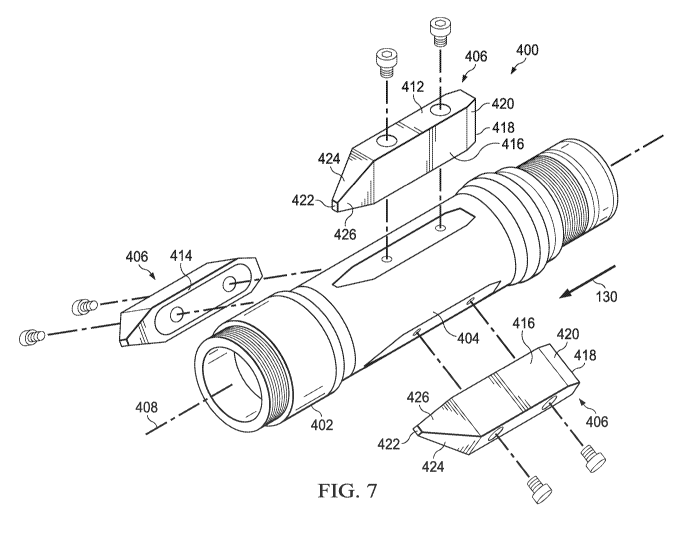
[0089]
Referring now to Figure 20, a fin 606 of a centralizer, generally designated
600, is shown. Fin 606 is substantially similar to fin 506, shown in Figures
10 to 12.
Fin 606 differs from fin 506 due to the presence of a chamfered transition
surface 607
arranged between and connecting the impact surface 618 and the wall interface
612,
such that the chamfered transition surface 607 has a larger angle (e.g., is
more
inclined) than the upstream angle (see 522, Figure 11) of the impact surface
518. The
chamfered transition surface 607 is advantageous in that the fin 606 may be
more
easily retrieved from a downhole installation (e.g., in borehole 104, Figure
1) than for
17
CA 03131793 2021-08-26
WO 2020/180926
PCT/US2020/020883
the fin 506. The provision of the chamfered transition surface 607 does not
cause
substantially greater erosive wear (e.g., does not reduce the wear life by
more than
5%, 10%, 20%, or 30%, depending on the shape, position, orientation, and size
of the
chamfered transition surface 607 relative to the impact surface 618 of the fin
606) on
the surfaces of the fin 606.
[0090]
Referring now to Figure 21, a damaged fin, generally designated 506A, is
shown. The damaged fin 506A illustrates that, after some attempts at
insertion,
retrieval, and or movement of the fin in a downhole installation (e.g., within
the a
borehole 104, Figure 1), some portions of the fin 506 may become structurally
compromised and fracture, crack, chip, or otherwise break off. In some cases,
the
broken off portion of the fin 506 may be carried away with the fluid flowing
past the
damaged fin 506A substantially immediately after the damage occurs. Figure 21
illustrates that even if an upstream portion (e.g., having the impact surface
518
originally formed on an external, upstream-facing surface thereof) of the fin
506,
between the original impact surface 518 and an upstream installation bolt
aperture 507
is removed, the fin 506 may have a redundant impact surface 509 that is only
exposed
to the erosive flow as an impact surface upon damage to, or removal of (e.g.,
by
fracture or breaking off) the original impact surface 518 of the fin 506. Upon
removal
of the original impact surface 518, the redundant impact surface 509 is
consequently
exposed to oncoming fluid flow. Although the redundant impact surface 509 may
perform better than a streamlined or smooth interface, such as the upstream
longitudinal end 318 of the prior art centralizer 300 (Figures 2 and 3), the
redundant
impact surface 509 may not provide degraded erosion prevention performance
compared to the erosion prevention performance of the original impact surface
518.
[0091] Referring now to
Figure 22, an upstream oblique view of a fifth example
embodiment of a centralizer, generally designated 700, is shown. The
centralizer 700
comprises a body 702 having a generally tubular shape (e.g., that of a hollow
cylinder), with a central reduced outside diameter section 704 arranged
between
flange sections arranged longitudinally on both opposing ends of the reduced
outside
diameter section 704. In some embodiments, the reduced outside diameter
section 704
may be in the form of a cylindrical band wrapped circumferentially around the
body
702, such that an outer surface of the reduced outside diameter section 704 is
substantially the same (e.g., within about 10%, within about 5%, within about
1%,
18
CA 03131793 2021-08-26
WO 2020/180926
PCT/US2020/020883
etc.) as the outer diameter of the body 702. The fins 706 may be attached to
either the
body or the reduced outside diameter section 704, including when the reduced
outside
diameter section 704 is in the form of a cylindrical band or tubular carrier,
for
example, using fasteners, welding, additive manufacturing, injection molding,
and the
like. In some embodiments, the reduced outside diameter section 704 is made
from a
same material as the fins 706. In some embodiments, the reduced outside
diameter
section 704 is made of a same material as the body 702. A plurality of fins,
generally
designated 706, are shown attached circumferentially to and about the reduced
outside
diameter section 704 of the centralizer 700, such that the fins are evenly
spaced (e.g.,
having a substantially uniform fin pitch) about the reduced outside diameter
section
704 and extend radially outwardly away from the reduced outside diameter
section
704. Like with fin 506, fin 706 is configured to similarly cause a localized
reduction
in velocity of fluid flow, and particularly of particulate matter entrained in
the fluid
flow, that contacts the fin 706 and to similarly cause turbulent fluid
shedding from the
impact surfaces of the fin 706. Figure 23 shows a side view of the centralizer
700.
Figure 24 shows a downstream oblique view of the centralizer 700. Figure 25
shows
a downstream end view of the centralizer 700. Figure 26 shows a cross-
sectional view
of the centralizer 700, through one of the fins 706, the cross-sectional view
being
taken along cutting line A-A of Figure 25.
[0092] Referring
now to Figure 27, an alternative embodiment of example
embodiment of a centralizer, generally designated 800, is shown. The
centralizer 800
comprises a body 802 having a generally tubular shape (e.g., that of a hollow
cylinder). In some embodiments, the centralizer 800 can have a central reduced
outside diameter section (e.g., such as 704, Figures 22-26) arranged between
flange
sections arranged longitudinally on both opposing ends of the reduced outside
diameter section. A plurality of fins, generally designated 806, are shown
attached
circumferentially to and about the body 802, such that the fins are evenly
spaced (e.g.,
having a substantially uniform fin pitch) about the body 802 and extend
radially
outwardly away from the body 804.. The fins 806 notably differ from other fins
disclosed herein (e.g., 406, 506, 606, 706) by comprising a curved transition
803
between the wall interface 812 and the downstream tail surface 820.
[0093] While
the centralizers and associated fins described herein have been
disclosed as being utilized with a hydrocarbon recovery system such as
hydrocarbon
19
CA 03131793 2021-08-26
WO 2020/180926
PCT/US2020/020883
recovery system 100, any such centralizers and fins, as well as combinations
thereof,
that are disclosed herein may be used in conjunction with any other suitable
systems
without deviating from the scope of the subject matter disclosed herein.
[0094] In
particular, the disclosed centralizers (400, 500, 600, 700, 800) and fins
(406, 506, 606, 706, 806) can be utilized in conjunction with a coiled tubing
drilling
system. The coiled tubing drilling system can comprise a reel carrying a roll
of coiled
tubing, a guide to help bend the coiled tubing through an injector and
associated
pressure containment device, an orienting device near a downhole end of the
coiled
tubing, data sensors near the downhole end of the coiled tubing, a motor near
the
downhole end of the coiled tubing, and a drilling bit. One or more of the
coiled tubing,
orienting device, data sensors, motor, and drilling bit may benefit from
either carrying
or being associated with (e.g., attached to) the centralizers (400, 500, 600,
700, 800)
and/or fins (406, 506, 606, 706, 806) disclosed herein. The centralizers
and/or fins
(406, 506, 606, 706, 806) disclosed herein can provide a desired centralizing
and/or
vibration damping effect to the coiled tubing system while still allowing the
necessary
fluid flow. In some cases, the centralizers and/or fins (406, 506, 606, 706,
806)
disclosed herein may be longitudinally reversed so that reverse flow of fluids
first
impact the above-described impact surfaces of the fins (406, 506, 606, 706,
806).
[0095] Further,
the centralizers and fins (406, 506, 606, 706, 806) disclosed can
be utilized in conjunction with a wireline logging system. The wireline
logging system
can comprise a winch configured to control dispensation of a cable, a logging
tool
configured to be deployed downhole sometimes through a casing, and a logging
unit
configure to receive and record information from the logging tool. One or more
of the
cable and logging tool may benefit from either carrying or being associated
with the
centralizers (400, 500, 600, 700, 800) and/or fins (406, 506, 606, 706, 806)
disclosed
herein.
[0096] While
some embodiments described above disclose a fin (406, 506, 606,
706, 806) being connected to a carrier (e.g., 402, 502, 602, 702, 802) by use
of a bolted
connection, other methods of attachment are contemplated. In particular, in
alternative
embodiments, a fin (406, 506, 606, 706, 806) may be connected to a carrier
(402, 502,
602, 702, 802) by being bonded to the carrier (402, 502, 602, 702, 802) , by
using a
compression fit or a slip-fit, by using a thermal fit, by using a band or a
clamp, and/or
by being integrally formed with the carrier (402, 502, 602, 702, 802). In some
CA 03131793 2021-08-26
WO 2020/180926
PCT/US2020/020883
embodiments, a fin (406, 506, 606, 706, 806) may be integrally formed with a
carrier
(402, 502, 602, 702, 802) using an additive manufacturing process.
[0097] In some
cases, the fins (406, 506, 606, 706, 806) described herein may
comprise an elastomer, polyurethane, nitrile, natural rubber, ethylene
propylene diene
monomer rubber, a temperature resistant synthetic elastomer, and/or a fluid
resistant
synthetic elastomer. Further, in some cases, a fin (406, 506, 606, 706, 806)
may
comprise a structural constituent dispersed within the primary fin material
and/or the
fin (406, 506, 606, 706, 806) may comprise structural elements such as bars or
plates
of structural material disposed within the primary fin material.
[0098] Referring now to
Figure 28, the prior art centralizer 300 is shown in a
condition after having been exposed to abrasive fluid flow. More specifically,
the prior
art centralizer 300 is shown after having been abraded and worn (e.g., eroded
due to
frictional impacts with particulate matter entrained in a fluid flow passing
around the
prior art centralizer 300) to form wash areas 301 of the fin 306 that have
experienced
a localized reduction in material due to the abrasive impacts of the
particulate matter
entrained in the fluid flow. The wash areas 301 are shown as being present on
leading
and trailing longitudinal ends 318, 319, respectively, of fins 306. In some
cases, a
wash area 301 is present on the carrier 302, between adjacent fins 306. Still
further,
in some cases abrasion may lead to a chunking area 303 on wall interface 312.
The
chunking area 303 represents a portion of the fin 306 where larger portions of
the
material of the fin 306 are removed relatively intact (e.g., not gradually, as
is the case
for erosive wear) as compared to the smoother and more gradual material
removal that
occurs in the wash areas 301.
[0099]
Referring now to Figure 29, the prior art centralizer 300 is shown in a
condition after having been exposed to abrasive fluid flow. More specifically,
the prior
art centralizer 300 is shown after having been abraded and worn (e.g., eroded
due to
frictional impacts with particulate matter entrained in a fluid flow passing
around the
prior art centralizer 300) to form wash areas 301 of the fin 306 that have
experienced
a localized reduction in material due to the abrasive impacts of the
particulate matter
entrained in the fluid flow. The wash areas 301 are shown as being present on
leading
and trailing longitudinal ends 318, 319, respectively, of fins 306. In some
cases, a
wash area 301 is present on the carrier 302, between adjacent fins 306.
21
CA 03131793 2021-08-26
WO 2020/180926
PCT/US2020/020883
[00100] Referring now to Figures 30 and 31, a fin, generally designated 906,
according to a seventh embodiment of a centralizer is shown. The fin 906 is
substantially similar to fin 406 (Figures 6 to 9), however, the fin 906
comprises a
sloped outer transition 919 between and/or connecting an upstream impact
surface
918 and a wall interface 912, such that the sloped outer transition 919 has a
larger
angle (e.g., is more inclined) than the upstream angle (see 522, Figure 11) of
the
upstream impact surface 918. The fin 906 also comprises a radially outward
downstream tail surface 924 that transitions radially inwardly toward a
truncated tip
surface 922 (e.g., so that the trailing portion of the fin 906 has a tapering,
or thinning,
profile in the radial and/or circumferential directions).
[00101] Referring now to Figures 32 and 32, a damaged fin, generally
designated
906A, is shown in a condition after having been exposed to (e.g., immersed in)
abrasive fluid flow over a period of time. Prior to being exposed to the
abrasive fluid
flow, the damaged fin 906A was substantially identical to the fin 906 of
Figures 30
and 31. More specifically, the damaged fin 906A has been abraded and worn
(e.g.,
eroded due to frictional impacts with particulate matter entrained in a fluid
flow
passing around the fin 906 of Figures 30 and 31) to form wash areas 903 of the
damaged fin 906A that have experienced a localized reduction in material due
to the
abrasive impacts of the particulate matter entrained in the fluid flow. The
wash areas
903 are shown as being present primarily at transitions (e.g., edges) between
the
upstream impact surface 918 and surfaces adjacent to (e.g., contiguous with)
the
upstream impact surface 918 and between the sloped outer transition 919 and
surfaces
adjacent to (e.g., contiguous with) the sloped outer transition 919. Wash
areas 703 are
also present around the entrances of mounting holes, which are formed on the
wall
interface 912 and/or through the thickness of the damaged fin 906A in the
radial
direction of the centralizer to which the damaged fin 906A is attached, and
between
the wall interface 912 and surfaces adjacent to (e.g., contiguous with) the
wall
interface 912.
[00102] Other embodiments of the current invention will be apparent to those
skilled in the art from a consideration of this specification or practice of
the invention
disclosed herein. Thus, the foregoing specification is considered merely
exemplary of
the current invention with the true scope thereof being defined by the
following
claims.
22