Note: Descriptions are shown in the official language in which they were submitted.
TITLE: BIPOD WITH SLING STUD MOUNT
[00011 __
FIELD OF THE DISCLOSURE
10002] The present disclosure relates generally to bipods. In particular, but
not by way of
limitation, the present disclosure relates to systems, methods and apparatuses
for a bipod
configured for coupling to a sling stud mount of a firearm.
DESCRIPTION OF RELATED ART
[0003] Modern firearms, such as rifles in particular, may be more accurately
and conveniently
fired by the shooter if the firearm is equipped with a bipod device for
supporting and
steadying the barrel. Bipods may be fixedly or removably mounted onto
firearms, and have
been found to be most convenient if they can further be retracted in a storage
position when
not in use. Exemplary bipods and mounting devices are taught in prior U.S.
Pat. No.
3,327,422 issued Jun. 27, 1967; U.S. Pat. No. 4,470,216 issued Sep. 11, 1984;
U.S. Pat.
No. 4,625,620 issued Dec. 2, 1986; and U.S. Pat. No. 4,641,451 issued Feb. 10,
1987; U.S.
Pat. No. 4,903,425 issued Feb. 27,1990; and U.S. Pat. No. 5,711,103 issued
Jan. 27,1998,
and U.S. Pat. No. 7,779,572 issued Aug. 24, 2010.
[00041 Existing bipeds attach to firearms via a number of interfaces including
M-LOK, NATO
Rail, Picatinny Rail, and the sling stud. The Harris Biped is one very common
bipod that
1
Date Recue/Date Received 2022-02-14
CA 03132383 2021-09-01
WO 2020/214803
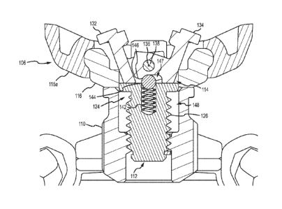
PCT/US2020/028498
attaches to the sling stud, but tends to be finicky and difficult to install.
Thus, there is a
need for a simpler and more secure method of attaching a bipod to a sling
stud, and one
that is quicker and less prone to mounting errors.
SUMMARY OF THE DISCLOSURE
[0005] The following presents a simplified summary relating to one or more
aspects and/or
embodiments disclosed herein. As such, the following summary should not be
considered
an extensive overview relating to all contemplated aspects and/or embodiments.
nor should
the following summary be regarded to identify key or critical elements
relating to all
contemplated aspects and/or embodiments or to delineate the scope associated
with any
particular aspect and/or embodiment. Accordingly, the following summary has
the sole
purpose to present certain concepts relating to one or more aspects and/or
embodiments
relating to the mechanisms disclosed herein in a simplified form to precede
the detailed
description presented below.
[0006] The present disclosure relates generally to a bipod-to-firearm
interface for a sling stud (or
sling swivel stud). More specifically, but without limitation, the present
disclosure relates
to a bipod having a firearm forend interface, a sling stud clasp assembly
optionally
including spring-loaded pawls that open and close to grasp a firearm's sling
stud, and these
pawls being biased toward an open position, and opening and closing of the
sling stud clasp
assembly being effected by rotation of a sling stud locking mechanism coupled
to the sling
stud clasp assembly. The sling stud clasp assembly can be arranged below and
partially
passing up and through an aperture in a mounting plate. The sling stud locking
mechanism
can be positioned below the firearm forend interface, and in some instances
can include a
2
CA 03132383 2021-09-01
WO 2020/214803
PCT/US2020/028498
rotating knob having a threading relationship to the sling stud clasp
assembly. More
specifically, the sling stud clasp assembly can include spring-loaded pawls
that pivot on a
pivot axis. The pivot axis can be held within a pivot holder having outer
threads on a lower
portion thereof that can threadingly couple to inner threads of the rotating
knob.
Accordingly, when the knob is rotated in a first direction, the pivot holder
is pulled
downward relative to the knob and mounting plate and consequently, the pivot
axis and the
spring-loaded pawls are also pulled downward relative to the knob and mounting
plate. As
the spring-loaded pawls are pulled downward through the aperture in the
mounting plate
they are pressed inward and can pivot or close on a sling stud thereby
grasping and locking
the sling stud to the bipod-to-firearm interface (e.g., see FIGs. 10-11).
Rotating the rotating
knob in a second direction forces the sling stud clasp assembly upward
allowing the spring-
loaded pawls to pivot outward as they clear a top of the aperture in the
mounting plate. The
pivot holder and the knob can be concentrically arranged around a vertical
axis that also
passes through a center of the sling stud (in other words, the knob and pivot
holder are
aligned along a common axis with the sling stud).
[0007] The firearm forend interface can include its own sling stud, for
instance, extending
rearward from a back of the firearm forend interface. This sling stud of the
bipod can
enable sling stud access for the user since the firearm's forend sling stud is
used to mount
the bipod and thus isn't available for a sling or other accessory attachment.
[0008] Generally, the bipod can include a housing with two leg assemblies
attached thereto. The
housing can include an aperture through which passes a pivot rod, the pivot
rod having a
threaded coupling to a locking knob arranged below the housing, wherein
turning of the
locking knob results in the pivot rod moving up or down along a vertical axis
passing
3
CA 03132383 2021-09-01
WO 2020/214803
PCT/US2020/028498
through the pivot rod and the housing. A top of the pivot rod can be coupled
to a cant nut
having a tubular shape and a longitudinal axis perpendicular to the vertical
axis. A firearm
forend interface can include an aperture having a similar shape to the cant
nut, and the cant
nut arranged within this aperture in the firearm forend interface. The firearm
forend
interface can rotate or cant around the cant nut to provide canting to a
firearm mounted to
the firearm forend interface. A pivot block can be arranged between the
housing and the
firearm forend interface and can pivot atop the housing. The pivot block can
include a
concave hollow into which a portion of a bottom of the firearm forend
interface is shaped
to rest in such that when the locking knob is tightened, the pivot block and
firearm forend
interface pivot in unison. Rotation of the locking knob pushes the cant nut
and thereby the
firearm forend interface up or down to lock or unlock the firearm forend
interface into the
concave hollow in the pivot block. The firearm forend interface can be shaped
to fit a
variety of known and yet-to-be-known accessory interfaces, such as, but not
limited, to M-
LOK, Picatinny rail, and NATO rail.
[0009] Some embodiments of the disclosure may be characterized as a bipod
assembly comprising
a firearm forend interface, a pivot holder. two pawls, and a sling stud
locking mechanism.
The firearm forend interface can have a vertical aperture shaped to receive
the pivot holder.
The pivot holder can be shaped to slidingly move vertically with the vertical
aperture in
the firearm forend interface. The two pawls can be pivotally coupled to each
other and
pivotally coupled to the pivot holder via a pivot pin. The sling stud locking
mechanism
can be threadingly coupled to the pivot holder and can be configured to cause
the vertical
movement of the pivot holder via rotation of the sling stud locking mechanism.
Upward
4
CA 03132383 2021-09-01
WO 2020/214803
PCT/US2020/028498
vertical movement of the pivot holder can cause opening of the two pawls,
whereas
downward vertical movement of the pivot holder can cause closing of the two
pawls.
[0010] Other embodiments of the disclosure can be characterized as a firearm
assembly. The
assembly may comprise a firearm having a forend. a firearm forend interface, a
pivot
holder, two pawls, and a sling stud locking mechanism. The firearm forend
interface can
be configured for coupling to a bottom of the forend and may have a vertical
aperture
shaped to receive a pivot holder. The pivot holder may be shaped to slidingly
move
vertically within the vertical aperture in the firearm forend interface. The
two pawls may
be pivotally coupled to each other and to the pivot holder via a pivot pin.
The sling stud
locking mechanism may be threadingly coupled to the pivot holder and
configured to, via
rotation of the sling stud locking mechanism, cause the vertical movement of
the pivot
holder. The movement of the pivot holder within the vertical aperture in a
first direction
may cause opening of the two pawls, and movement of the pivot holder within
the vertical
aperture in a second direction may cause closing of the two pawls
BRIEF DESCRIPTION OF THE DRAWINGS
[0011] Various objects and advantages and a more complete understanding of the
present
disclosure are apparent and more readily appreciated by referring to the
following
detailed description and to the appended claims when taken in conjunction with
the
accompanying drawings:
[0012] FIG. 1 shows a perspective view of an embodiment of the herein
disclosed bipod coupled
to a generic firearm forend;
CA 03132383 2021-09-01
WO 2020/214803
PCT/US2020/028498
[0013] FIG. 2 shows another perspective view of an embodiment of the herein
disclosed bipod
coupled to a generic firearm forend;
[0014] FIG. 3 shows two flanges that can be used on the bipod shown in FIGs. 1
and 2;
[0015] FIG. 4 shows a view of the bipod without a flange;
[0016] FIG. 5 shows a detailed view of the bipod interfacing with a sling stud
of a firearm;
[0017] FIG. 6 illustrates details of the sling stud clasp assembly and the
sling stud locking
mechanism;
[0018] FIG. 7 illustrates a detailed and exploded view of the sling stud clasp
assembly and the
sling stud locking mechanism;
[0019] FIG. 8 illustrates the pivot holder, pivot pin, and pawls in isolation
with a sling stud;
[0020] FIG. 9 illustrates another view of the pawls, pivot pin, and sling stud
shown in FIG. 8;
[0021] FIG. 10 shows the sling stud clasp assembly in the open position,
without a sling stud
shown;
[0022] FIG. 11 shows the sling stud clasp assembly in the closed position and
grasping the
firearm sling stud;
[0023] FIG. 12A shows a first position of the pawls in the sling stud clasp
assembly;
[0024] FIG. 12B shows a second position of the pawls in the sling stud clasp
assembly;
[0025] FIG. 12C shows a third position of the pawls in the sling stud clasp
assembly;
[0026] FIG. 13 shows a profile view of the firearm forend interface and a
sling stud extending
rearward from a rear of the firearm forend interface; and
[0027] FIG. 14 shows an isometric view of a left, top, rear of the firearm
forend interface in FIG.
13.
6
CA 03132383 2021-09-01
WO 2020/214803
PCT/US2020/028498
DETAILED DESCRIPTION
[0028] The word "exemplary" is used herein to mean "serving as an example,
instance, or
illustration." Any embodiment described herein as "exemplary" is not
necessarily to be
construed as preferred or advantageous over other embodiments.
[0029] FIGs. 1 and 2 show perspective views of an embodiment of the herein
disclosed bipod
coupled to a generic firearm forend 101. The bipod enables selective and
lockable cant
and pivoting and interfacing with a firearm, such as a rifle, via one of
various known
interfacing platforms (e.g., M-LOK, NATO Rail, Picatinny). The legs can also
telescope
and be stored in a position folded up and back to a position near the forend
101 of the
firearm and parallel to the barrel (e.g., rotated roughly 90 from a deployed
position). The
bipod can further include legs 102 rotationally coupled to a housing 104. The
housing 104
can include a pivot block 107 that couples to the firearm forend interface
106. In this
embodiment, the firearm forend interface 106 is configured for interfacing
with a firearm,
handguard of a firearm, etc. via the sling stud platform. A sling stud locking
mechanism
110, arranged below the firearm forend interface 106, can rotate in a first
direction to loosen
the bipod from the sling stud and allow the bipod to be removed from the
firearm. Rotating
the sling stud locking mechanism 110 in a second direction can tighten a
coupling between
the bipod and the sling stud of the firearm to secure the bipod to the
firearm. The firearm
forend interface 106 can couple to the housing 104 via the pivot block 107. In
other
embodiments this coupling can include different degrees of rotational freedom
(e.g., cant
and pivot to name two). In the illustrated embodiments, structures to allow
cant and pivot
between the housing 104 and the firearm forend interface 106 are shown, but
these are not
intended to limit the scope of the disclosure.
7
100301 The legs 102, housing 104, locking knob 108, and pivot block 107 are
substantially the
same as described in U.S. Patent Nos. 10,161,706 and 10,168,119.
[0031] FIGs. 3-5 show a sling stud clasp assembly 112 coupled to a sling stud,
such as a sling stud
that was used to couple the forend 101 to the bipod in FIG. 1. The sling stud
clasp assembly
112 is arranged within an aperture 114 in the firearm forend interface 106 and
is rotatably
coupled to and controlled by a sling stud locking mechanism 110 (e.g., a
rotating knob)
below a front overhanging portion of the Firearm forend interface 106. FIGs.
10 and 11
show a cross section of the same. FIGs. 3-5 exclude the firearm to make it
easier to view
portions of the biped that are otherwise obscured from view. However, a sling
stud 120 of
the firearm is still visible to illustrate interaction with the sling stud
clasp assembly 112
(shown in a "closed" or "locked" position or state). The sling stud clasp
assembly 112 is
arranged through an aperture 114 in the firearm forend interface 106 (this
aperture is more
easily seen in FIGs. 10 and 11). The aperture 114 can extend through the
firearm forend
interface 106, from a top to a bottom of the firearm forend interface 106, and
the sling stud
clasp assembly 112 can pass through this aperture 114 to couple to the sling
stud locking
mechanism 110 (e.g., via a threaded engagement). For instance, the sling stud
locking
mechanism 110 can form a rotational coupling to the sling stud clasp assembly
112 (the
sling stud locking mechanism 110 can rotate, which in turn causes the sling
stud clasp
assembly 112 to move up and down). The sling stud locking mechanism 110 can be
moved
toward a locked position (e.g., via rotation in a first direction) to move the
sling stud clasp
assembly 112 front an open to a closed position and thereby lock it onto the
firearm sling
stud 120. This motion can overcome a bias on the sling stud clasp assembly
112, caused
8
Date Recue/Date Received 2022-02-14
CA 03132383 2021-09-01
WO 2020/214803
PCT/US2020/028498
by a biasing component 142 and detent 144, and force the sling stud clasp
assembly 112
toward the closed position. For instance, rotation of the sling stud locking
mechanism 110
in a first direction can cause a pair of spring-loaded pawls 132, 134 of the
sling stud clasp
assembly 112 (see FIGs. 6-12) to close or rotate inward around a pivot axis
136 (see FIG.
7). Rotation, especially via a threaded engagement, can effect a large torque
able to
overcome the bias from the biasing component 142 that otherwise forces the
pawls 132,
134 toward an open position in which they are not in contact with the firearm
sling stud
120. Further details describing opening and closing of the pawls 132, 134 can
be seen in
FIGs. 10-12.
[0032] In some embodiments, the firearm forend interface 106 can comprise two
components: a
soft flange (not shown in FIG. 4, but visible as 115 in FIGs. 3 and 10-11) and
a mounting
plate 116 (shown in FIGs. 4 and 10-11). The mounting plate 116 can couple to a
bottom
of the soft flange 115 and can interface the firearm forend interface 106 to
the rest of the
bipod (e.g., to the pivot block 107). In some cases, the mounting plate 116
can include
structure for cant movement relative to the bipod housing (i.e., rotation
around an axis
parallel with the longitudinal axis of the firearm barrel).
[0033] FIG. 5 illustrates another view of the mounting plate 116, but with the
soft flange 115
removed.
[0034] FIG. 3 also shows two variations of the firearm forend interface 106: a
version having a
wider soft flange 115a (left) and a version having a narrower soft flange 115b
(right).
These and other firearm forend interfaces 106 can be adapted to different
sizes and shapes
of firearm forends, and are non-limiting. The soft flange 115 can be formed
from rubber,
9
CA 03132383 2021-09-01
WO 2020/214803
PCT/US2020/028498
cloth, polymer, or any other material unlikely to scratch the forend of the
rifle that the bipod
is being attached to (e.g., wooden forends).
[0035] FIG. 6 illustrates details of the sling stud clasp assembly 112 and the
sling stud locking
mechanism 110. The left figure shows the sling stud clasp assembly 112 in the
open
position, and the right figure shows the sling stud clasp assembly 112 in the
closed position
and clamped to a firearm sling stud 120. The sling stud locking mechanism 110
can also
include a first spring-loaded pawl 132 and a second spring-loaded pawl 134
both rotatably
coupled to a pivot holder 124 via a pivot pin 138 passing along a pivot axis
136 parallel to
a longitudinal axis of the firearm barrel. The spring-loaded pawls 132, 134
can each
include protrusions 122, 123 shaped to enter an opposing side of an aperture
in the firearm
sling stud 120 when the pawls 132, 134 close upon the firearm sling stud 120.
The pivot
holder 124 can also include a threaded lower portion 126, the cylindrical
upper portion
128, and a pawl-holding recess 130 within the cylindrical section 128 (see
FIG. 7). The
pawl-holding recess 130 can be shaped and sized to receive at least a portion
of both of the
pawls 132, 134. An outer diameter of the cylindrical section 128 can have a
similar (or
just smaller) diameter than an inner diameter of a lock aperture 148 through
the sling stud
locking mechanism 110. This enables the cylindrical section 128 to slide
vertically within
the lock aperture 148. The pivot axis 136 and pivot pin 138 can pass through
the pawls
132, 134, the cylindrical section 128 of the pivot holder 124, and the pawl-
holding recess
130. Accordingly, when the sling stud locking mechanism 110 is rotated, inner
threads
thereof interface with outer threads of the threaded lower portion 126 causing
the pivot
holder 124 to move upward or downward within the lock aperture 148. This
movement
CA 03132383 2021-09-01
WO 2020/214803
PCT/US2020/028498
pulls the pivot pin 138 with the pivot holder 124 which in turn pulls the
pawls 132, 134 up
and down, which causes opening and closing of the pawls 132, 134.
[0036] The loosening and tightening of the sling stud clasp assembly 112 is
best seen in FIGs. 10-
12. Notably, the cross section in FIG. 10 shows the sling stud clasp assembly
112 in the
open position, without a sling stud shown, and FIG. 11 shows the sling stud
clasp assembly
112 in the closed position and grasping the firearm sling stud 120. One or
both of the
spring-loaded pawls 132, 134 can include an irregular bottom surface, and
different
portions of this irregular bottom surface are presented to and contact the
detent 144 as the
pivot holder 124 moves within the aperture 114. In turn, this contact leads to
different
torques applied to the pawls 132, 134. More specifically, the irregular
surface can include
one or both of a pawl detent 146 and a pawl groove 147. Both the pawl detent
146 and the
pawl groove 147 can include curved surfaces and the pawl groove 147 can be
closer to the
pivot axis 136 than the pawl detent 146. In other words, a first radius from
the pawl detent
146 to the pivot axis 136 can be greater than a second radius from the pawl
groove 147 to
the pivot axis 136. However, the pawl detent 146 and/or pawl groove 147 can
include one
or more straight surfaces as well, or one or more straight surfaces joined by
beveled edges,
corners, or jogs. The pawl detent 146 can be arranged toward an outside of
each pawl 132,
134. The detent 144 can interact with the pawl groove 147 when the spring-
loaded pawls
132, 134 are in the open position as well as with an inside side of the detent
146 (see FIG.
12A), and can interact solely with the pawl detent 146 when the pawls 132, 134
are in the
closed position (see FIG. 12C).
[0037] FIG. 12 shows opening and closing of the pawls in three stages from
open (FIG. 12A) to
closed (FIG. 12C). In the open position the pawl groove 147 is in contact with
a top of the
11
CA 03132383 2021-09-01
WO 2020/214803
PCT/US2020/028498
detent 144 and the detent 144 is in a topmost position of the three stages
shown in FIG. 12.
Here the pawls 132, 134, via the pawl groove 147, apply little if any pressure
downward
on the top of the detent 144. The detent 144 can be arranged partially in the
vertical
aperture 140 and partly in the pawl-holding recess 130. A biasing component
142 (e.g., a
spring) can also be arranged in the vertical aperture between a bottom of the
detent 144
and a bottom of the vertical aperture 140. However, this position of the
biasing component
is not limiting. This biasing component 142 can apply a bias on the detent 144
tending to
push it upward toward the pawls 132, 134. The knob 110, the pivot holder 124,
and the
vertical aperture 140 can all be aligned along a common axis that passes
through a center
of the sling stud (as best seen in FIG. 8). This axis may also pass through
the detent 144,
and the detent 144 may move up and down along this axis.
[0038] Specifically, as the sling stud locking mechanism 110 is rotated in a
first direction, the
threaded portion 126 of the pivot holder 124 threadingly engages inner threads
of the sling
stud locking mechanism 110 and this interaction pulls the pivot holder 124
downward.
Downward movement of the pivot holder 124 brings the pivot pin 138 with it,
and with
this comes the spring-loaded pawls 132, 134 (see FIG. 12B). As the spring-
loaded pawls
132, 134 are pulled downward with the pivot holder 124, the sides of the pawls
132, 134
contact edges of the aperture 114 in the mounting plate 116 and this gradually
forces the
pawls 132, 134 inward. At the same time, as the pawls 132, 134 rotate, the
pawl detent
146 pivots downward relative to the pivot axis 136 and begins to interface
with and press
down on a top of the detent 144. This causes the biasing component 142 to
become
compressed and increase an upward bias on the detent 144, which in turn
increases its bias
on the pawl detent 146 (even as the pawls 132, 134 continue to pivot inward
toward a
12
CA 03132383 2021-09-01
WO 2020/214803
PCT/US2020/028498
closed position). In other words, as the pawls 132. 134 are closed, the bias
on them to open
increases.
[0039] As the sling stud locking mechanism 110 continues to rotate in the
first direction, the pivot
holder 124 continues to descend further pulling the pawls 132, 134 inward and
clamping
them into a horizontal aperture in the sling stud (not shown) until a fully
closed position is
reached at FIG. 12C and the bipod is secured to the sling stud and hence the
firearm.
[0040] From the closed position in FIG. 12C, the sling stud locking mechanism
110 can be rotated
in a second direction to cause the pivot holder 124 to move upward. One can
see how
upward movement of the pivot holder 124 causes the detent 144 to first contact
the pawl
detent 146 since at this angle, the pawl detent 146 sits lower in the system
than the pawl
groove 147. As this upward movement continues, the detent 144 can interact
with an
angled side of the pawl detent 146 and cause the pawls 132, 134 to pivot
outward (or begin
to open) as they move upward and clear a top of the aperture 114. This outward
pivoting
can be caused by upward pressure from the detent 144 on the pawl detent 146
(clockwise
in FIG. 11 for pawl 134). As the pivot holder 124 rises further and the pawls
132, 134
further clear the top of the aperture 114, the detent 144 continues to force
the spring-loaded
pawls 132, 134 toward the open position until they reach the position shown in
FIG. 12A.
Here, the biasing component 142 is at a maximum extension for the three
figures in FIG.
12, though it still may remain under some compression such that an upward bias
remains
on the detent 144.
[0041] A bottom outer edge of each pawl 132. 134 may include an angled surface
that aligns with
a top of the pivot holder 124 when the pawls 132, 134 are fully-opened, as
best seen in
13
CA 03132383 2021-09-01
WO 2020/214803
PCT/US2020/028498
FIGs. 10 and 12A. These angled surfaces can prevent overextension of the pawls
132, 134
(i.e., prevent excessive outward pivoting). For instance, in FIG. 12A, the
pawls 132, 134
are not able to pivot any further outward. In some embodiments, only one of
the pawls
132, 134 may include this angled surface at the bottom outer edge.
[0042] While FIGs. 10-12 show a specific irregular bottom surface to the
detent 144 that may
include a pawl detent 146 and a groove detent 147, other irregular surfaces
can also be
implemented as long as a rotational bias (or torque) is maintained on the
pawls 132, 134
throughout a range of vertical motion of the pivot holder 124.
[0043] In FIGs. 7-12 only a single pawl detent 146 and pawl groove 147 are
visible, however the
other pawl may or may not also include its own pawl detent 146 and pawl groove
147. A
bottom surface of either or both of the pawls 132, 134 can be described as
irregular as
shown throughout the figures.
[0044] A clevis 125 (see FIG. 7) can prevent the sling stud clasp assembly 112
and the sling stud
locking mechanism 110 from pulling apart and decoupling when the sling stud
locking
mechanism 110 is rotated in a second direction (e.g., a loosening direction).
FIGs. 10 and
11 show the wider soft flange 115a shown in the left of FIG. 3, though other
sizes and
shapes of soft flanges can be implemented without departing from the scope of
this
disclosure (e.g., the narrower soft flange 115b).
[0045] FIG. 8 illustrates the pivot holder 124, pivot pin 138, and pawls 132,
134 in isolation with
a sling stud 120. The pawls 132, 134 are in an open position, but one can see
how the
protrusions 122, 123 are aligned to enter a horizontal aperture through the
sling stud 120.
14
CA 03132383 2021-09-01
WO 2020/214803
PCT/US2020/028498
[0046] FIG. 9 illustrates another view of the pawls 132. 134, pivot pin 138,
and sling stud 120
shown in FIG. 8.
[0047] It should be understood that the detent 146 and groove 147 are just one
example of an
interface structure between the spring-loaded pawls 132, 134 and the detent
144, and other
interfaces are also contemplated without departing from the scope of this
disclosure.
Further, although the detent 144 is shown as a sphere, in other embodiments, a
cylindrical
plunger or curved component could also be implemented. In another embodiment,
part of
the detent 144 could be curved or even spherical, while another portion could
be cylindrical
(e.g., a lower portion could be cylindrical and an upper portion could be
curved). For
instance, the detent. 144 could have a "bullet" shape.
[0048] Non-limiting examples of the biasing component include, a compression
spring, a conical
spring, a coil spring, leaf spring, disc or Bellevile spring, barrel spring,
elliptical helical
spring, volute spring, and a pneumatic plunger. Non-limiting examples of the
detent 144
include a curved or spherical detent, a cylindrical detent, and a pointed
detent.
[0049] FIG. 13 shows a profile view of the firearm forend interface 106 and a
sling stud 1302
extending rearward from a rear of the firearm forend interface 106. FIG. 14
shows an
isometric view of a left, top, rear of the firearm forend interface 106.
Although the sling
stud 1302 is shown extending rearward parallel to a longitudinal axis of the
firearm barrel,
in other embodiments, any angle oblique to the firearm sling stud 120 can be
used, and the
sling stud 1302 can be arranged on other portions of the firearm forend
interface 106.
However, given the location of the firearm forend, the bipod legs 102, and the
sling stud
locking mechanism 110, as well as the fact that slings tend to also be coupled
to a fixture
CA 03132383 2021-09-01
WO 2020/214803
PCT/US2020/028498
toward the rear of the firearm, a rearward position for the sling stud 1302
may be optimal
for user access as well as optimal alignment with tension forces from a sling.
[0050] As used herein, the recitation of "at least one of A, B and C" is
intended to mean "either A,
B, C or any combination of A, B and C." The previous description of the
disclosed
embodiments is provided to enable any person skilled in the art to make or use
the present
disclosure. Various modifications to these embodiments will be readily
apparent to those
skilled in the art, and the generic principles defined herein may be applied
to other
embodiments without departing from the spirit or scope of the disclosure.
Thus, the present
disclosure is not intended to be limited to the embodiments shown herein but
is to be
accorded the widest scope consistent with the principles and novel features
disclosed
herein.
16