Note: Descriptions are shown in the official language in which they were submitted.
ELECTRONIC DEVICE AND METHOD FOR
CONTROLLING ELECTRONIC DEVICE
TECHNICAL FIELD
[0001] This disclosure relates to the field of communications
technologies, and
.. in particular, to an electronic device and a method for controlling an
electronic
device.
BACKGROUND
[0002] With continuous development of display technology, users are
gradually
imposing higher requirements on display performance of electronic devices. In
order
to increase a screen-to-body ratio, the design of full screen (for example,
ultra-narrow bezel) has gradually become the mainstream of current researches.
[0003] Using a mobile terminal as an example, in the related art, a front
cover of
a mobile terminal typically includes a frame region for placing components
such as
a camera or a distance detection sensor (for example, a proximity detection
sensor).
In order to implement the design of full screen, the components placed in the
front
cover of the terminal need to be re-arranged.
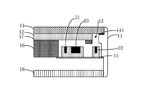
[0004] In order to reduce impact of the distance detection sensor on the
screen-to-body ratio, a design scheme of placing a distance detection sensor
under a
screen is provided in the related art. However, infrared emission under the
screen
with the screen on has greater impact on the reliability of the screen.
[0005] It can be learned that the design scheme of placing a distance
detection
sensor under the screen in the related art has a problem of relatively great
impact on
the reliability of the screen.
Date Reetie/Date Received 2023-03-02
SUMMARY
[0006] Embodiments of this disclosure provide an electronic device and a
method for controlling an electronic device, so as to resolve the problem that
the
design scheme of placing a distance detection sensor under a screen in the
related art
has a problem of relatively great impact on reliability of the screen.
[0007] In order to resolve the foregoing technical problem, this
disclosure is
implemented as follows:
[0008] According to a first aspect, an embodiment of this disclosure
further
provides an electronic device. The electronic device includes a first side and
a
second side that are disposed facing away from each other, and a frame is
disposed
between the first side and the second side.
[0009] The first side is provided with a display module, the display
module is at
least partially light-permeable, and a gap is present between the display
module and
the frame.
[0010] A first light emitting device, a second light emitting device, and a
light
receiving device are provided inside the electronic device, the first light
emitting
device and the light receiving device are both disposed below the display
module
and disposed corresponding to a light-permeable display region of the display
module, the first light emitting device emits a light signal to the outside
through the
light-permeable display region, and the second light emitting device emits a
light
signal to the outside through the gap.
[0011] According to a second aspect, an embodiment of this disclosure
further
provides a method for controlling an electronic device, applied to the
electronic
device described above. The method includes:
obtaining a working status of the display module of the electronic device;
controlling the second light emitting device to emit a light signal in a
case that the display module of the electronic device is in a light-on state,
where the
first light emitting device is in an off state; and
2
Date Reetie/Date Received 2023-03-02
controlling the first light emitting device to emit a light signal in a case
that the display module of the electronic device is in a light-off state,
where the
second light emitting device is in an off state.
[0012] According to a third aspect, an embodiment of this disclosure
further
provides an electronic device, including a processor, a memory, and a computer
program stored in the memory and capable of running on the processor. When the
computer program is executed by the processor, the steps of the foregoing
method
for controlling an electronic device are implemented.
[0013] According to a fourth aspect, an embodiment of this disclosure
further
provides a computer-readable storage medium. The computer-readable storage
medium stores a computer program, and when the computer program is executed by
the processor, the steps of the foregoing method for controlling an electronic
device
are implemented.
[0014] In the embodiments of this disclosure, the first light emitting
device and
the light receiving device are both disposed below the display module and
disposed
corresponding to the light-permeable display region of the display module; the
first
light emitting device emits a light signal to the outside through the light-
permeable
display region; and the second light emitting device emits a light signal to
the
outside through the gap. In this way, the second light emitting device can be
used to
emit a light signal when the electronic device is in a screen-on state,
thereby
reducing impact of distance detection on reliability of the screen and the
screen-to-body ratio, and also ensuring that implementation of distance
detection
when the screen of the electronic device is in different states.
BRIEF DESCRIPTION OF DRAWINGS
[0015] To describe the technical solutions in the embodiments of the
present
disclosure more clearly, the following briefly describes the accompanying
drawings
required for describing the embodiments of the present disclosure. Apparently,
the
accompanying drawings in the following description show merely some
3
Date Reetie/Date Received 2023-03-02
embodiments of the present disclosure, and a person of ordinary skill in the
art may
still derive other drawings from these accompanying drawings without creative
efforts.
[0016] FIG. 1 is a first schematic structural diagram of a cross-section
of an
electronic device according to an embodiment of this disclosure;
[0017] FIG. 2 is a schematic diagram of a light signal propagation path
according to an embodiment of this disclosure;
[0018] FIG. 3 is a second schematic structural diagram of a cross-section
of an
electronic device according to an embodiment of this disclosure;
[0019] FIG. 4 is a front view of an electronic device according to an
embodiment of this disclosure;
[0020] FIG. 5 is a first flowchart of a method for controlling an
electronic
device according to an embodiment of this disclosure;
[0021] FIG. 6 is a second flowchart of a method for controlling an
electronic
device according to an embodiment of this disclosure; and
[0022] FIG. 7 is a structural diagram of an electronic device according
to an
embodiment of this disclosure.
DESCRIPTION OF EMBODIMENTS
[0023] The following clearly and completely describes the technical
solutions in
the embodiments of the present disclosure with reference to the accompanying
drawings in the embodiments of the present disclosure. Apparently, the
described
embodiments are merely a part rather than all of the embodiments of the
present
disclosure. All other embodiments that a person of ordinary skill in the art
obtains
without creative efforts based on the embodiments of the present disclosure
shall
fall within the protection scope of the present disclosure.
[0024] An embodiment of this disclosure provides an electronic device.
The
following describes this embodiment of this disclosure with reference to FIG.
1 to
FIG. 4.
4
Date Reetie/Date Received 2023-03-02
[0025] Referring to FIG. 1, FIG. 1 is a schematic cross-sectional view of
an
electronic device according to an embodiment of this disclosure. As shown in
FIG.
1, the electronic device includes a first side and a second side that are
disposed
facing away from each other, and a frame 11 is disposed between the first side
and
the second side.
[0026] The first side is provided with a display module 12, the display
module
12 is at least partially light-penneable, and a gap 13 is present between the
display
module 12 and the frame 11.
[0027] A first light emitting device 21, a second light emitting device
22, and a
light receiving device 23 are provided inside the electronic device. The first
light
emitting device 21 and the light receiving device 23 are both disposed below
the
display module 12 and disposed corresponding to a light-peimeable display
region
of the display module 12. A light signal is emitted outside the electronic
device
through the light-permeable display region, and the second light emitting
device 22
emits a light signal to the outside through the gap 13.
[0028] In this embodiment, the display module 12 may be, but is not
limited to,
an organic light-emitting diode (Organic Light-Emitting Diode, OLED) display
module.
[0029] The first light emitting device 21 and/or the second light
emitting device
22 may be an infrared light emitting diode (Light Emitting Diode, LED), an
infrared
laser transmitter, or the like.
[0030] The light receiving device 23 may be an infrared receiving sensor.
It
should be noted that the number of the light receiving devices 23 may be one
or at
least two, which is not limited in this embodiment. For example, a plurality
of light
emitting devices may correspond to a same light receiving device, or the light
emitting device may be in one-to-one correspondence to the light receiving
device.
[0031] Specifically, at least part or all of a display region of the
display module
12 is light-permeable. The light signal emitted by the first light emitting
device 21
passes through the light-permeable display region of the display module 12 and
may
be received by the light receiving device 23 after being reflected. The light
signal
5
Date Reetie/Date Received 2023-03-02
emitted by the second light emitting device 22 passes through the gap 13 and
may
be received by the light receiving device 23 after being reflected.
[0032] In practical applications, distance measurement can be implemented
by
using the first light emitting device 21, the second light emitting device 22,
and the
light receiving device 23. Optionally, a distance between the electronic
device and a
reflective object may be calculated based on a time difference between
emitting the
light signal by the first light emitting device 21 and receiving, by the light
receiving
device 23, the light signal that is emitted by the first light emitting device
21 and
reflected by the reflective object; or a distance between the electronic
device and the
reflective object may be calculated based on a time difference between
emitting the
light signal by the second light emitting device 22 and receiving, by the
light
receiving device 23, the light signal that is emitted by the second light
emitting
device 22 and reflected by the reflective object.
[0033] It should be noted that in a proximity detection process,
proximity
determining may be performed directly based on a reflection value detected by
the
light receiving device, or proximity determining may be performed by
calculating a
distance between the electronic device and the reflective object (for example,
the
user answering the call) based on the light signal emitted by the second light
emitting device and a reflected signal received by the light receiving device.
This is
not limited in this embodiment.
[0034] A distance between the light receiving device 23 and the first
light
emitting device 21 and a distance between the light receiving device 23 and
the
second light emitting device 22 may be set properly based on an actual
requirement,
so as to ensure that the light receiving device 23 can receive light signals
that are
emitted by the first light emitting device 21 and the second light emitting
device 22
and reflected by the reflective object. Optionally, a distance between the
second
light emitting device 22 and a light receiving midpoint of the light receiving
device
23 may be 3 mm to 4.5 mm, thereby improving detection effects for a black
reflective object.
6
Date Reetie/Date Received 2023-03-02
[0035] As shown in FIG. 2, the light signal emitted by the first light
emitting
device 21 may pass through the display module 12, travels outside the
electronic
device, and then is received by the light receiving device 23 after being
reflected by
the reflective object 2. The light signal emitted by the second light emitting
device
22 may pass through the gap 13, travels outside the electronic device, and
then is
received by the light receiving device 23 after being reflected by the
reflective
object 2.
[0036] In practical applications, emitting a light signal in the screen-
on state,
that is, when the screen is displayed, by the light emitting device disposed
under the
screen easily affects the display of the screen, thereby affecting the
reliability of the
screen. Therefore, in this embodiment, in a case that the display module 12 of
the
electronic device is in a light-off state, the first light emitting device 21
located
under the display module 12 may be used to emit a light signal; and in a case
that
the display module 12 of the electronic device is in an on state, the second
light
emitting device 22 may be used to emit a light signal, thereby reducing impact
on
the screen from the light emitting device disposed under the screen, and also
ensuring implementation of distance detection when the screen of the
electronic
device is in different states.
[0037] In addition, the first light emitting device 21 and the light
receiving
device 23 are both disposed below the display module 12 and also disposed
corresponding to the light-permeable display region of the display module 12;
and
the second light emitting device 22 is disposed facing towards the gap 13
between
the display module 12 and the frame 11, so as to reduce a frame region for
placing
the devices and reduce impact of the devices on the screen-to-body ratio.
[0038] Optionally, as shown in FIG. 3, a light guide rod 31 is provided in
the
gap 13, and the second light emitting device 22 emits a light signal to the
outside
through the light guide rod 31 in the gap 13.
[0039] In this embodiment, the light signal emitted by the second light
emitting
device 22 can be received by the light receiving device 23 after passing
through the
light guide rod 31 and being reflected.
7
Date Reetie/Date Received 2023-03-02
[0040] Specifically, a material of the light guide rod 31 may be
transparent
plastic, transparent acrylic, or the like. The light guide rod 31 may be, but
is not
limited to, a rectangular structure, an L-shaped structure, or the like. The
light guide
rod 31 may be fastened on the frame 11 or a mounting bracket. The light guide
rod
31 may include a light exit surface 311 facing towards the first side and a
light
incident surface 312 facing towards the second light emitting device 22. The
light
signal emitted by the second light emitting device 22 enters the light
incident
surface 312 of the light guide rod 31 and then travels outside the electronic
device
through the light exit surface 311 of the light guide rod 31.
[0041] In this embodiment, because the light guide rod 31 is disposed in
the gap
13 between the display module 12 and the frame 11, and the light signal
emitted by
the second light emitting device 22 can be conducted to the outside of the
electronic
device through the light guide rod 31, thereby reducing impact of the second
light
emitting device on the screen-to-body ratio and also improving the light-focus
effect.
[0042] Optionally, the electronic device further includes a light-
permeable cover
plate 14, the light-penneable cover plate 14 is provided with a glue
dispensing
region 141, the light guide rod 31 is disposed directly opposite the glue
dispensing
region 141, and a light exit surface 311 of the light guide rod 31 is bonded
to the
.. glue dispensing region 141.
[0043] In this embodiment, the light-permeable cover plate 14 may be a
light-permeable cover plate such as a glass cover plate or an organic plastic
cover
plate. The light-permeable cover plate 14 is disposed on the first side and
may be
used to cover the display module 12 of the electronic device, so as to protect
the
display module 12. The light-permeable cover plate 14 is provided with a glue
dispensing region 141. As shown in FIG. 3, the glue dispensing region 141 may
be
used to secure the light guide rod 31 on the light-permeable cover plate 14.
[0044] Optionally, a width of the light exit surface 311 of the light
guide rod 31
is less than or equal to a width of the glue dispensing region 141.
8
Date Reetie/Date Received 2023-03-02
[0045] In this embodiment, the width of the light exit surface 311 of the
light
guide rod 31 is less than or equal to the width of the glue dispensing region
141.
Therefore, an additional gap does not need to be additionally disposed,
thereby
further reducing impact of the second light emitting device on the screen-to-
body
ratio and implementing the narrower-bezel design.
[0046] Optionally, the light guide rod 31 and the frame 11 are formed as
a
whole through injection molding.
[0047] In this embodiment, the light guide rod 31 and the frame 11 are
formed
as a whole through injection molding, thereby ensuring stability of the light
guide
rod and reducing the width of the gap. Optionally, as shown in FIG. 3, the
width of
the light exit surface 311 of the light guide rod 31 may be equal to the width
of the
glue dispensing region 141, thereby improving light exit effects.
[0048] Optionally, the light exit surface 311 of the light guide rod 31
comes in
contact with the glue dispensing region 141.
[0049] In this embodiment, the light exit surface 311 of the light guide
rod 31
comes in contact with the glue dispensing region 141, thereby improving light
exit
effects.
[0050] Optionally, a width of the light incident surface 312 of the light
guide
rod 31 is greater than the width of the light exit surface 311 of the light
guide rod
31.
[0051] In this embodiment, the width of the light incident surface 312 of
the
light guide rod 31 is greater than the width of the light exit surface 311 of
the light
guide rod 31, thereby improving light focus effects. For example, as shown in
FIG.
3, the light guide rod 31 has an L-shaped structure.
[0052] Optionally, the second light emitting device 22 is disposed directly
opposite the light exit surface 311 of the light guide rod 31.
[0053] In this embodiment, as shown in FIG. 3, the second light emitting
device
22 is disposed directly opposite the light exit surface 311 of the light guide
rod 31,
thereby improving light exit effects.
9
Date Reetie/Date Received 2023-03-02
[0054] Optionally, an infrared light receiving element and an ambient
light
receiving element are integrated in the light receiving device 23.
[0055] In this embodiment, the infrared light receiving element may be
used to
receive infrared light, which is, for example, infrared light that is emitted
by the
infrared light emitting element and reflected by a reflective object.
Specifically, the
infrared light receiving element may cooperate with the infrared light
emitting
element to implement distance measurement. The ambient light receiving
element,
such as a photosensitive receiving element, may be used to receive ambient
light to
implement ambient light detection.
[0056] In this embodiment, the infrared light receiving element and the
ambient
light receiving element are integrated in the light receiving device 23,
thereby
further reducing impact of the ambient light receiving element on the screen-
to-body
ratio, improving compactness of the internal space layout of the electronic
device,
and saving interior space of the electronic device.
[0057] Optionally, an infrared light emitting element, an infrared light
receiving
element, and an ambient light receiving element are integrated in the second
light
emitting device 22.
[0058] In this embodiment, the infrared light emitted by the infrared
light
emitting element may travel through the gap and then is received by the
infrared
light receiving element, to implement distance measurement. The ambient light
receiving element, such as a photosensitive receiving element, may be used to
receive ambient light to implement ambient light detection.
[0059] In this embodiment, the infrared light emitting element, the
infrared light
receiving element, and the ambient light receiving element are integrated in
the
second light emitting device 22, thereby further reducing impact of the
ambient light
receiving element on the screen-to-body ratio, also improving compactness of
the
internal space layout of the electronic device, and reducing interior space of
the
electronic device.
[0060] Optionally, as shown in FIG. 4, the first light emitting device
21, the
second light emitting device 22, and the light receiving device 23 may be
disposed
Date Reetie/Date Received 2023-03-02
in a middle region along the width direction of the electronic device, for
example, a
middle region of an earpiece end of the electronic device.
[0061] In practical applications, when making or receiving a phone call
by using
the electronic device, a user usually moves the middle region of the earpiece
end of
the electronic device to the ear. Therefore, disposing the first light
emitting device
21, the second light emitting device 22, and the light receiving device 23 in
the
middle region of the earpiece end of the electronic device leads to a more
accurate
detection result during proximity detection.
[0062] It should be noted that the first light emitting device 21 may be
located
on an upper side, a lower side, a left side, or a right side of the light
receiving device
23, which is not limited in this embodiment. FIG. 4 merely shows that the
first light
emitting device 21 is located on a lower side of the light receiving device
23.
[0063] Optionally, the first light emitting device 21, the second light
emitting
device 22, and the light receiving device 23 may be fastened on a reinforcing
plate
15, a raised bracket, a main board, or the like. Further, the first light
emitting device
21, the second light emitting device 22, and the light receiving device 23 can
be
fastened on the same reinforcing plate, raised bracket, or main board, thereby
making the internal layout of the electronic device more simple and compact.
[0064] Optionally, as shown in FIG. 1 to FIG. 3, the electronic device
may
further include but is not limited to a frame support 16, a light-shielding
foam 17
provided between the frame support 16 and the display module 12, a back cover
18,
and so on. The light-shielding foam 17 may be black light-shielding foam.
[0065] The following uses proximity detection for the electronic device
(for
example, a mobile terminal) as an example to describe this embodiment of this
disclosure.
[0066] In a case of an incoming call, the display module of the
electronic device
is in a light-on state, that is, the electronic device is in a screen-on
state. In this case,
the second light emitting device is controlled to emit a light signal for
distance
measurement. If it is detected that a distance between the electronic device
and the
reflective object is greater than or equal to a first preset value, the
display module
11
Date Reetie/Date Received 2023-03-02
may remain in the light-on state, and the second light emitting device may be
continuously controlled to emit a light signal for distance measurement. If it
is
detected that the distance between the electronic device and the reflective
object is
less than the first preset value, the display module may be turned off, that
is, the
screen is turned off, the second light emitting device is turned off, and the
first light
emitting device is controlled to emit a light signal for distance measurement.
The
first preset value may be 3 cm.
[0067] In a process in which the first light emitting device emits light
signals for
distance measurement, if it is detected that the distance between the
electronic
device and the reflective object is less than or equal to a second preset
value, the
display module may remain in the light-off state, and the first light emitting
device
may be continuously controlled to emit a light signal for distance
measurement. if it
is detected that the distance between the electronic device and the reflective
object is
greater than the second preset value, the display module may be turned on, the
first
light emitting device is turned off, and the second light emitting device
emits light
signals for distance measurement. The second preset value may be 5cm.
[0068] It should be noted that proximity determining may be performed
directly
based on a reflection value detected by the light receiving device, which is
not
limited in this embodiment.
[0069] The design solution of dual-tunnel distance detection provided in
this
embodiment can not only reduce impact of a distance detection device on the
screen-to-body ratio and reliability of the screen, but also ensure a more
accurate
detection result.
[0070] An embodiment of this disclosure further provides a method for
controlling an electronic device, applied to the electronic device provided in
any one
of the foregoing embodiments. Referring to FIG. 5, FIG. 5 is a flowchart of a
method for controlling an electronic device according to an embodiment of this
disclosure. As shown in FIG. 5, the method includes the following steps.
[0071] Step 501: Obtain a working status of a display module of an
electronic
device.
12
Date Reetie/Date Received 2023-03-02
[0072] In this embodiment, obtaining the working status of the display
module
of the electronic device may be performed when a trigger signal for distance
detection is received. Specifically, the receiving the trigger signal for
distance
detection may be receiving an incoming call signal, receiving a preset
operation, or
the like. The preset operation may be a preset operation for triggering
distance
measurement, for example, a tapping operation on a distance measurement
control.
The working status of the display module may include a light-on state and a
light-off state.
[0073] It should be noted that the obtaining the working status of the
display
module of the electronic device may also be obtaining perfointed in other
cases.
[0074] Step 502: In a case that the display module of the electronic
device is in
the light-on state, control the second light emitting device to emit a light
signal,
where the first light emitting device is in the light-off state.
[0075] In this step, when the display module of the electronic device is
in the
light-on state, the second light emitting device may be controlled to emit a
light
signal to perfoun distance measurement. In this case, the first light emitting
device
is in an off state, that is, the first light emitting device does not emit a
light signal at
this time.
[0076] Step 503: In a case that the display module of the electronic
device is in
the light-off state, control the first light emitting device to emit a light
signal, where
the second light emitting device is in the turned-off state.
[0077] In this step, when the display module of the electronic device is
in the
light-off state, the first light emitting device may be controlled to emit a
light signal
to perform distance measurement. In this case, the second light emitting
device is in
an off state, that is, the second light emitting device does not emit a light
signal at
this time.
[0078] It should be noted that the electronic device in this embodiment
may
include a structural composition of the electronic device in any one of the
foregoing
embodiments, with the same technical effects achieved. In order to avoid
repetition,
details are not described herein again. In the method for controlling an
electronic
13
Date Reetie/Date Received 2023-03-02
device provided in this embodiment of this disclosure, the first light
emitting device
is controlled to emit a light signal in a case that the display module is in
the light-off
state; and the second light emitting device is controlled to emit a light
signal in a
case that the display module is in the light-on state. This can not only
reduce impact
of distance detection on the reliability of the screen, but also ensure a more
accurate
detection result.
[0079] Optionally, after the controlling the second light emitting device
to emit
a light signal in the case that the display module of the electronic device is
in the
light-on state, the method may further include:
in a case that the display module of the electronic device is detected to
have switched to the light-off state, controlling the first light emitting
device to emit
a light signal, and turning off the second light emitting device.
[0080] After the controlling the first light emitting device to emit a
light signal
in the case that the display module of the electronic device is in the light-
off state,
the method may further include:
in a case that the display module of the electronic device is detected to
have switched to the light-on state, controlling the second light emitting
device to
emit a light signal, and turn off the first light emitting device.
[0081] In this embodiment, in a continuous distance measurement process,
if it
is detected that the display module changes from the light-on state to the
light-off
state, the first light emitting device may be controlled to emit a light
signal, and the
second light emitting device may be turned off, thereby improving accuracy of
a
detection result. If it is detected that the display module changes from the
light-off
state to the light-on state, the processor may control the second light
emitting device
to emit a light signal, and turns off the first light emitting device, thereby
reducing
impact of the distance detection on the reliability of the screen.
[0082] The following uses proximity detection for the electronic device
(for
example, a mobile terminal) as an example to describe this embodiment of this
disclosure. As shown in FIG. 6, the method for controlling an electronic
device
provided in this embodiment of this disclosure includes the following steps.
14
Date Reetie/Date Received 2023-03-02
[0083] Step 601: In a case that an incoming call is detected, control the
electronic device to be in a screen-on state, and control the second light
emitting
device to emit a light signal.
[0084] In this step, when the electronic device detects an incoming call,
if the
electronic device is in the screen-off state, the electronic device may be
controlled to
enter the screen-on state, and if the electronic device is already in the
screen-on
state, the electronic device may remain in the screen-on state, the second
light
emitting device is controlled to emit a light signal, and the light receiving
device
receives the light signal that is emitted by the second light emitting device
and
reflected by the reflective object.
[0085] In practical applications, in the case of an incoming call, the
user usually
moves the electronic device close to the ear to answer the call. In this case,
the
second light emitting device emits a light signal for proximity determining,
so as to
detect whether the electronic device is close to the ear of the user or detect
whether
the electronic device is far away from the ear of the user.
[0086] In this embodiment, proximity determining may be performed
directly
based on a reflection value detected by the light receiving device, or
proximity
determining may be performed by calculating a distance between the electronic
device and the reflective object (for example, the user answering the call)
based on
the light signal emitted by the second light emitting device and a reflected
signal
received by the light receiving device.
[0087] It should be noted that a closer distance between the electronic
device
and the reflective object (for example, the user answering the call) indicates
a
greater reflection value detected by the light receiving device. This
embodiment is
described below by using proximity determining based on the reflection value
detected by the light receiving device as an example.
[0088] Step 602: Determine whether the detected reflection value is
greater than
or equal to a first threshold.
[0089] In this embodiment, the light receiving device may include a photo
diode
(Photo Diode, PD), and the detected reflection value may be a reflection value
Date Reetie/Date Received 2023-03-02
detected by the PD. The first threshold may be set based on actual
requirements. For
example, the first threshold may be a reflection value corresponding to a
distance of
3 cm.
[0090] In this step, in a case that the detected reflection value is less
than the
first threshold, it indicates a current state being still far away, and step
603 may be
performed. When the detected reflection value is greater than or equal to the
first
threshold, step 604 is performed.
[0091] Step 603: Keep the electronic device in the screen-on state.
[0092] In this step, the electronic device may remain in the screen-on
state, and
the second light emitting device is still used to emit a light signal. After
the detected
reflection value is obtained, proceed with step 602.
[0093] Step 604: Control the electronic device to be in the screen-off
state, and
control the first light emitting device to emit a light signal.
[0094] In this step, in a case that the detected reflection value is
greater than or
equal to the first threshold, it indicates a current state being close; the
electronic
device may be controlled to be in the screen-off state, the first light
emitting device
may be controlled to emit a light signal, and the light receiving device may
receive a
light signal that is emitted by the first light emitting device and reflected
by the
reflective object. In this case, the second light emitting device is in the
turned-off
.. state.
[0095] Step 605: Determine whether the detected reflection value is less
than or
equal to a second threshold.
[0096] In this embodiment, the second threshold may be set properly based
on
an actual requirement, for example, being a reflection value corresponding to
a
distance of 5 cm.
[0097] In this step, in the case that the first light emitting device
emits a light
signal and the reflection value detected by the light receiving device is
greater than
the second threshold, it indicates a current state being close, and step 606
is
performed; otherwise, step 607 is performed.
[0098] Step 606: Keep the electronic device in the screen-off state.
16
Date Reetie/Date Received 2023-03-02
[0099] In this step, the electronic device may remain in the screen-off
state, and
the first light emitting device is still used to emit a light signal. After
the detected
reflection value is obtained, proceed with step 605.
[00100] Step 607: Control the electronic device to be in the screen-on state,
and
control the second light emitting device to emit a light signal.
[00101] In this step, in the case that the detected reflection value is less
than or
equal to the second threshold, it indicates a current state being far away,
and the
electronic device may be controlled to be in the screen-on state, and the
second light
emitting device may be controlled to emit a light signal. In this case, the
first light
emitting device is in the turned-off state.
[00102] It should be noted that proximity detection may be stopped in a case
that
termination of the call is detected.
[00103] Referring to FIG. 7, FIG. 7 is a structural diagram of an electronic
device
according to an embodiment of this disclosure. As shown in FIG. 7, the
electronic
device 700 includes:
an obtaining module 701, configured to obtain a working status of a
display module of the electronic device;
a first control module 702, configured to: control a second light emitting
device to emit a light signal in a case that the display module of the
electronic
device is in a light-on state, where a first light emitting device is in an
off state; and
a second control module 703, configured to: control the first light
emitting device to emit a light signal in a case that the display module of
the
electronic device is in a light-off state, where the second light emitting
device is in
an off state.
[00104] Optionally, the electronic device may further include:
a third control module, configured to: after the second light emitting
device is controlled to emit a light signal in the case that the display
module of the
electronic device is in the light-on state, in a case that the display module
of the
electronic device is detected to have switched to the light-off state, control
the first
17
Date Reetie/Date Received 2023-03-02
light emitting device to emit a light signal, and turn off the second light
emitting
device.
[00105] The electronic device may further include:
a fourth control module, configured to: after the first light emitting
device is controlled to emit a light signal in the case that the display
module of the
electronic device is in the light-off state, in a case that the display module
of the
electronic device is detected to have switched to the light-on state, control
the
second light emitting device to emit a light signal, and turn off the first
light
emitting device.
[00106] The electronic device 700 provided in this embodiment of this
disclosure
is capable of implementing processes that are implemented by the electronic
device
in the foregoing method embodiment. To avoid repetition, details are not
described
herein again.
[00107] In the electronic device 700 in this embodiment of this disclosure,
the
obtaining module 701 is configured to receive the trigger signal for distance
detection and obtain the working status of the display module of the
electronic
device; the first control module 702 is configured to: control the second
light
emitting device to emit a light signal in a case that the display module of
the
electronic device is in a light-on state; and the second control module 703 is
configured to: control the first light emitting device to emit a light signal
in a case
that the display module of the electronic device is in a light-off state. This
can not
only reduce impact of distance detection on the reliability of the screen and
the
screen-to-body ratio, but also ensure a more accurate detection result when
the
screen of the electronic device is in different states.
[00108] Optionally, an embodiment of this disclosure further provides an
electronic device, including a memory, a processor, and a computer program
stored
in the memory and capable of running on the processor. When the computer
program is executed by the processor, the processes of the foregoing
embodiment of
the method for controlling an electronic device are implemented, with the same
technical effect achieved. To avoid repetition, details are not described
herein again.
18
Date Reetie/Date Received 2023-03-02
[00109] An embodiment of this disclosure further provides a computer-readable
storage medium, where a computer program is stored in the computer-readable
storage medium. When the computer program is executed by a processor, the
processes of the foregoing embodiment of the method for controlling an
electronic
device are implemented, with the same technical effects achieved. To avoid
repetition, details are not described again herein. The computer-readable
storage
medium is, for example, a read-only memory (Read-Only Memory, ROM), a
random access memory (Random Access Memory, RAM), a magnetic disk, or an
optical disc.
[00110] It should be noted that the terms "include", "comprise", or any of
their
variants are intended to cover a non-exclusive inclusion, such that a process,
a
method, an article, or an apparatus that includes a list of elements not only
includes
those elements but also includes other elements that are not expressly listed,
or
further includes elements inherent to such process, method, article, or
apparatus. In
absence of more constraints, an element preceded by "includes a..." does not
preclude existence of other identical elements in the process, method,
article, or
apparatus that includes the element.
[00111] According to the description of the foregoing implementations, a
person
skilled in the art can clearly understand that the method in the foregoing
embodiments may be implemented by software in addition to a necessary
universal
hardware platfolin or by hardware only. In most cases, the former is a more
preferred implementation. Based on such an understanding, the technical
solutions
of this disclosure essentially, or the part contributing to the related art,
may be
implemented in a form of a software product. The software product is stored in
a
storage medium (such as a ROM/RAM, a magnetic disk, or an optical disc), and
includes several instructions for instructing a terminal (which may be a
mobile
phone, a computer, a server, an air conditioner, a network device, or the
like) to
perform the methods described in the embodiments of this disclosure.
[00112] The embodiments of the present disclosure are described above with
reference to the accompanying drawings, but the present disclosure is not
limited to
19
Date Reetie/Date Received 2023-03-02
such embodiments. The embodiments are only illustrative rather than
restrictive.
Inspired by the present disclosure, a person of ordinary skill in the art can
still
derive a plurality of variations without departing from the essence of the
present
disclosure and the protection scope of the claims. All these variations shall
fall
within the protection of the present disclosure.
Date Reetie/Date Received 2023-03-02