Note: Descriptions are shown in the official language in which they were submitted.
Ref. No. 68673-CA
HORIZONTAL WIRE FEED SPOOL DELIVERY SYSTEM
BACKGROUND
100011 In some welding-type applications, a welding wire feeder may be used
to feed
welding wire from a wire spool to a welding torch for a welding operation. In
some welding-
type operations, it may be desirable for welding wire feeders to be portable
and/or stackable.
SUMMARY
100021 The present disclosure relates generally to welding systems and,
more particularly,
to welding wire feeders and welding wire-feeder systems, substantially as
illustrated by and
described in connection with at least one of the figures, as set forth more
completely in the
claims.
100031 According to a first aspect, a wire-feeder system comprises: a base
platform; a spool
hub mounted to the base platform perpendicular to the base platform and
configured to support
a wire spool; a drive roll assembly mounted to the base platform, and having
one or more sets
of drive rollers configured to feed wire from the wire spool toward a welding
torch; and a wire
guide assembly mounted to the base platform separately from both the wire
spool and the drive
roll assembly, the wire guide assembly configured to guide the wire from the
wire spool
supported on the spool hub to the one or more sets of drive rollers.
100041 In certain aspects, each drive roller of the one or more sets of
drive rollers is
configured to rotate about an axis of rotation that is perpendicular to the
base platform.
100051 In certain aspects, the base platform is horizontal.
100061 In certain aspects, the base platform comprises a plurality of
supports to support a
second wire-feeder system above the base platform.
100071 In certain aspects, the plurality of supports comprises at least
three supports to
support a base platform of the second wire-feeder system.
1
Date Recue/Date Received 2021-10-05
Ref. No. 68673-CA
100081 In certain aspects, the wire guide assembly comprises a first guide
feature having a
first wire pass-through and a second guide feature having a second wire pass-
through, wherein
each of the first guide feature and the second guide feature protrude from the
base platform.
100091 In certain aspects, the first guide feature and the second guide
feature are each
removably coupled to the wire guide assembly.
100101 In certain aspects, the first guide feature is positioned between
the wire spool and
the second guide feature.
100111 In certain aspects, the first wire pass-through is larger than the
second wire pass-
through.
100121 In certain aspects, the wire guide assembly comprises a wire pass-
through that is
tapered from an inlet to an outlet.
100131 In certain aspects, the base platform comprises a plurality of
wheels to allow the
base platform to move across a surface.
100141 In certain aspects, the base platform comprises a set of forklift
pockets.
100151 In certain aspects, the base platform comprises a hoist attachment
to enable the base
platform to be suspended.
100161 In certain aspects, the wire-feeder system is configured to drive
wire having a
diameter that is between 1/16 and 1/8 inches.
100171 According to a second aspect, a method for configuring a wire-feeder
system in a
welding-type system comprises: loading a wire spool to a spool hub mounted to
a base
platform, wherein the spool hub 150 is perpendicular to the base platform;
passing welding
wire from the wire spool to a wire guide assembly that is separate from the
wire spool; and
driving the welding wire from the wire guide assembly to a welding torch via a
drive roll
assembly having one or more sets of drive rollers.
2
Date Recue/Date Received 2021-10-05
Ref. No. 68673-CA
100181 In certain aspects, the method further comprises the step of
stacking a second wire-
feeder system on top of the wire-feeder system.
100191 In certain aspects, each drive roller of the one or more sets of
drive rollers is
configured to rotate about an axis of rotation that is perpendicular to the
base platform.
100201 According to a third aspect, a wire-feeder system comprises: a base
platform; a
spool hub mounted to the base platform perpendicular to the base platform and
configured to
support a wire spool; a drive roll assembly mounted to the base platform, and
having one or
more sets of drive rollers configured to feed wire from the wire spool toward
a welding torch,
wherein each drive roller of the one or more sets of drive rollers is
configured to rotate about
an axis of rotation that is perpendicular to the base platform; and a wire
guide assembly
mounted to the base platform separately from both the wire spool and the drive
roll assembly,
the wire guide assembly configured to guide the wire from the wire spool
supported on the
spool hub to the one or more sets of drive rollers, wherein the wire guide
assembly comprises
a first guide feature having a first wire pass-through and a second guide
feature having a second
wire pass-through.
100211 In certain aspects, the first guide feature is positioned between
the wire spool and
the second guide feature, and wherein the first wire pass-through is larger
than the second wire
pass-through.
100221 In certain aspects, the base platform comprises a set of forklift
pockets.
100231 In certain aspects, the base platform comprises a plurality of
supports to support a
second wire-feeder system stacked above the base platform.
DRAWINGS
100241 The foregoing and other aspects, features, and advantages of the
devices, systems,
and methods described herein will be apparent from the following description
of particular
embodiments thereof, as illustrated in the accompanying figures; where like or
similar
3
Date Recue/Date Received 2021-10-05
Ref. No. 68673-CA
reference numbers refer to like or similar structures. The figures are not
necessarily to scale,
emphasis instead being placed upon illustrating the principles of the devices,
systems, and
methods described herein.
100251 Figure 1 illustrates an example welding system, in accordance with
aspects of this
disclosure.
100261 Figure 2a illustrates a top plan view of an example implementation
of the welding-
type system of Figure 1.
100271 Figure 2b illustrates a side view of the example implementation of
the welding-type
system of Figure 1.
100281 Figure 3a illustrates a front perspective view of an example wire
guide assembly
according to a first aspect.
100291 Figure 3b illustrates a rear perspective view of the example wire
guide assembly of
Figure 3a.
100301 Figure 3c illustrates a cross-sectional side view of an example wire
guide assembly
according to a second aspect.
100311 Figure 4 illustrates three example wire feeders systems stacked upon
one another,
in accordance with aspects of this disclosure.
100321 Figure 5 illustrates two example wire feeders systems stacked upon a
hand cart, in
accordance with aspects of this disclosure.
100331 Figure 6 illustrates an example method for configuring a wire-feeder
system in a
welding-type system.
DESCRIPTION
100341 References to items in the singular should be understood to include
items in the
plural, and vice versa, unless explicitly stated otherwise or clear from the
text. Grammatical
conjunctions are intended to express any and all disjunctive and conjunctive
combinations of
4
Date Recue/Date Received 2021-10-05
Ref. No. 68673-CA
conjoined clauses, sentences, words, and the like, unless otherwise stated or
clear from the
context. Recitation of ranges of values herein are not intended to be
limiting, referring instead
individually to any and all values falling within and/or including the range,
unless otherwise
indicated herein, and each separate value within such a range is incorporated
into the
specification as if it were individually recited herein. In the following
description, it is
understood that terms such as 'first," -second," -top," -bottom," -side," -
front," -back," and
the like are words of convenience and are not to be construed as limiting
terms. For example,
while in some examples a first side is located adjacent or near a second side,
the terms 'first
side" and -second side" do not imply any specific order in which the sides are
ordered.
100351 The terms -about," -approximately," -substantially," or the like,
when
accompanying a numerical value, are to be construed as indicating a deviation
as would be
appreciated by one of ordinary skill in the art to operate satisfactorily for
an intended purpose.
Ranges of values and/or numeric values are provided herein as examples only,
and do not
constitute a limitation on the scope of the described embodiments. The use of
any and all
examples, or exemplary language (-e.g.," such as," or the like) provided
herein, is intended
merely to better illuminate the embodiments and does not pose a limitation on
the scope of the
embodiments. The terms -e.g.," and for example" set off lists of one or more
non-limiting
examples, instances, or illustrations. No language in the specification should
be construed as
indicating any unclaimed element as essential to the practice of the
embodiments.
100361 The term -and/or" means any one or more of the items in the list
joined by -and/or."
As an example, ``x and/or y" means any element of the three-element set {(x),
(y), (x, y)}. In
other words, ``x and/or y" means one or both of x and y". As another example,
``x, y, and/or
z" means any element of the seven-element set {(x), (y), (z), (x, y), (x, z),
(y, z), (x, y, z)}. In
other words, ``x, y, and/or z" means one or more of x, y, and z."
Date Recue/Date Received 2021-10-05
Ref. No. 68673-CA
100371 The term ``welding-type system," as used herein, includes any device
capable of
supplying power suitable for welding, plasma cutting, induction heating, CAC-A
and/or hot
wire welding/preheating (including laser welding and laser cladding),
including inverters,
converters, choppers, resonant power supplies, quasi-resonant power supplies,
etc., as well as
control circuitry and other ancillary circuitry associated therewith.
100381 The term ``welding-type power" refers to power suitable for welding,
plasma
cutting, induction heating, CAC-A and/or hot wire welding/preheating
(including laser welding
and laser cladding). As used herein, the term ``welding-type power supply"
and/or ``power
supply" refers to any device capable of, when power is applied thereto,
supplying welding,
plasma cutting, induction heating, CAC-A and/or hot wire welding/preheating
(including laser
welding and laser cladding) power, including but not limited to inverters,
converters, resonant
power supplies, quasi-resonant power supplies, and the like, as well as
control circuitry and
other ancillary circuitry associated therewith.
100391 The terms -circuit" and -circuitry" includes any analog and/or
digital components,
power and/or control elements, such as a microprocessor, digital signal
processor (DSP),
software, and the like, discrete and/or integrated components, or portions
and/or combinations
thereof.
100401 The terms -control circuit" and -control circuitry," as used herein,
may include
digital and/or analog circuitry, discrete and/or integrated circuitry,
microprocessors, digital
signal processors (DSPs), and/or other logic circuitry, and/or associated
software, hardware,
and/or firmware. Control circuits or control circuitry may be located on one
or more circuit
boards, that form part or all of a controller, and are used to control a
welding process, a device
such as a power source or wire feeder, motion, automation, monitoring, air
filtration, displays,
and/or any other type of welding-related system.
6
Date Recue/Date Received 2021-10-05
Ref. No. 68673-CA
100411 The term -memory" and/or ``memory device" means computer hardware or
circuitry to store information for use by a processor and/or other digital
device. The memory
and/or memory device can be any suitable type of computer memory or any other
type of
electronic storage medium, such as, for example, read-only memory (ROM),
random access
memory (RAM), cache memory, compact disc read-only memory (CDROM), electro-
optical
memory, magneto-optical memory, programmable read-only memory (PROM), erasable
programmable read-only memory (EPROM), electrically-erasable programmable read-
only
memory (EEPROM), flash memory, solid state storage, a computer-readable
medium, or the
like.
100421 The term torch," -welding torch," ``welding tool," or -welding-type
tool" refers to
a device configured to be manipulated to perform a welding-related task, and
can include a
hand-held welding torch, robotic welding torch, gun, or other device used to
create the welding
arc.
100431 The term ``welding mode," ``welding process," ``welding-type
process," or ``welding
operation" refers to the type of process or output used, such as current-
controlled (CC), voltage-
controlled (CV), pulsed, gas metal arc welding (GMAW), flux-cored arc welding
(FCAW), gas
tungsten arc welding (GTAW), shielded metal arc welding (SMAW), spray, short
circuit,
and/or any other type of welding process.
100441 The present methods and systems may be realized in hardware,
software, and/or a
combination of hardware and software. Example implementations include an
application
specific integrated circuit and/or a programmable control circuit. The present
methods and/or
systems may be realized in a centralized fashion in at least one computing
system, or in a
distributed fashion where different elements are spread across several
interconnected
computing systems. Any kind of computing system or other apparatus adapted for
carrying out
the methods described herein is suited. A typical combination of hardware and
software may
7
Date Recue/Date Received 2021-10-05
Ref. No. 68673-CA
be a general-purpose computing system with a program or other code that, when
being loaded
and executed, controls the computing system such that it carries out the
methods described
herein. Another typical implementation may comprise an application specific
integrated circuit
or chip. Some implementations may comprise a non-transitory machine-readable
(e.g.,
computer readable) medium (e.g., FLASH drive, optical disk, magnetic storage
disk, or the
like) having stored thereon one or more lines of code executable by a machine,
thereby causing
the machine to perform processes as described herein.
100451 In some welding-type operations, such as gas metal arc welding
(GMAW), welding
wire may be fed by a wire feeder to a torch for a welding operation. Welding
large weldments,
such as those used for buildings, structural members, rail, mining, off-shore,
and the like, often
employ heavy weld spools with weld wire having a larger diameter. For example,
larger
weldments sometime run spools of wire that have a diameter of 1/8 or 3/32
inches. Depending
on the spooled wire length, these spools can weight about 25 to 100 pounds,
typically about 50
to 60 pounds. Existing wire feeders typically employ a vertically-mounted wire
spool assembly
that directs the wire to the driver roller via various wire guides coupled to
the vertically-
mounted wire spool assembly or the driver roller. In some applications or job
sites, it may be
desirable to move the wire feeder to different locations at the job site in
order to avoid driving
the wire from the wire feeder to the torch over a long distance. Therefore, it
is also desirable
for wire feeders to be portable.
100461 Employing heavy, larger diameter wire increases the wear and tear on
the welding
equipment, while also making it more difficult to store and to transport
around the job site. For
example, existing systems can suffer from inlet guide wear, drive assembly
wear, mobility
concerns, and a need for improved over all ruggedness for the large weldment
environment.
As can be appreciated, addressing these issues would result in less equipment
down time, less
8
Date Recue/Date Received 2021-10-05
Ref. No. 68673-CA
repair, and increased mobility/safety. Further, as will be described, the wire
feeder disclosed
herein will also be easier to stack, store, and deploy; thus, improving fleet
management.
100471 The present disclosure relates to a wire-feeder system that includes
a horizontally-
mounted wire spool assembly and an external wire guide assembly. Employing a
horizontally-
mounted wire spool assembly and an external wire guide assembly can offer a
number of
advantages. For example, it is easier to load and unload a horizontally-
mounted wire spool
(e.g., a fifty or sixty pound spool of welding wire). Further, mounting the
wire spool
horizontally improves the weight distribution, thus improving the ability to
move the feeder.
Additionally, a horizontally-mounted wire spool design improves storage and
deployment of
the wire-feeder system (e.g., on a cart, sled, with the power source,
forklift, casters, etc.). For
example, a wire-feeder system with a horizontally-mounted wire spool is more
compact,
balanced, and may be more easily stacked. Finally, the external wire guide
assembly improves
the longevity of the drive system by reducing the load on the inlet guides and
drive assemblies.
An external wire guide assembly can also more readily repaired or replaced.
Therefore, the
wire-feeder system of the present disclosure may feed weld wire of a larger
diameter as
compared to conventional suitcase wire feeders while increasing reliability,
portability, and
ease of use on the jobsite.
100481 Figure 1 illustrates an example welding system 100 for performing
welding-type
operations. As shown in the welding system 100 of Figure 1, a power supply 102
and a wire-
feeder system 104 are coupled via conductors or conduits 106. In the
illustrated example, the
power supply 102 is separate from the wire-feeder system 104, such that the
wire-feeder system
104 may be positioned near a welding location at some distance from the power
supply 102.
Terminals are typically provided on the power supply 102 and on the wire-
feeder system 104
to allow the conductors or conduits 106 to be coupled to the systems so as to
allow for power
9
Date Recue/Date Received 2021-10-05
Ref. No. 68673-CA
and gas to be provided to the wire-feeder system 104 from the power supply
102, and to allow
data to be exchanged between the two devices.
100491 The system 100 is configured to provide welding wire 112 from a
welding wire
source 114, power from the power supply 102, and shielding gas from a
shielding gas supply
116, to a welding torch 118. The welding torch 118 may be any type of arc
welding torch, (e.g.,
GMAW, GTAW, FCAW) and may allow for the feed of a welding wire 112 (e.g., an
electrode
wire) and gas to a location adjacent to a welding work piece 108. A work cable
110 is run to
the welding work piece 108 so as to complete an electrical circuit between the
power supply
102 and the welding work piece 108 via a clamp 126.
100501 The welding system 100 is configured for weld settings (e.g., weld
parameters, such
as voltage, wire feed speed, current, gas flow, inductance, physical weld
parameters, advanced
welding programs, pulse parameters, etc.) to be selected by the operator
and/or a welding
sequence, such as via an operator interface 120 provided on the power supply
102. The operator
interface 120 will typically be incorporated into a front faceplate of the
power supply 102, and
may allow for selection of settings such as the weld process, the type of wire
to be used, voltage
and current settings, and so forth. In particular, the example system 100 is
configured to allow
for welding with various steels, aluminums, or other welding wire that is
channeled through
the welding torch 118. Further, the system 100 is configured to employ welding
wires with a
variety of wire sizes. For example, between 1/16 and 1/8 inches, though other
sizes are
contemplated. These weld settings are communicated to a control circuit 122
within the power
supply 102. The system may be particularly adapted to implement welding
regimes configured
for certain electrode types.
100511 The control circuit 122, operates to control generation of welding
power output that
is supplied to the welding wire 112 for carrying out the desired welding
operation.
Date Recue/Date Received 2021-10-05
Ref. No. 68673-CA
100521 The welding torch 118 applies power from the power supply 102 to the
welding
wire 112, typically by a welding cable 124. Similarly, shielding gas from a
shielding gas supply
116 is fed through the wire-feeder system 104 and the welding cable 124.
During welding
operations, the welding wire 112 is advanced through a jacket of the welding
cable 124 towards
the welding torch 118 via the wire-feeder system 104.
100531 The work cable 110 and clamp 126 allow for closing an electrical
circuit from the
power supply 102 through the welding torch 118, the welding wire 112
(electrode), and the
welding work piece 108 for maintaining the welding arc during the operation.
100541 The control circuit 122 is coupled to power conversion circuit 128.
This power
conversion circuit 128 is adapted to create the output power, such as pulsed
waveforms applied
to the welding wire 112 at the welding torch 118. Various power conversion
circuits may be
employed, including choppers, boost circuitry, buck circuitry, inverters,
converters, and/or
other switched mode power supply circuitry, and/or any other type of power
conversion
circuitry. The power conversion circuit 128 is coupled to a source of
electrical power as
indicated by arrow 130. The power applied to the power conversion circuit 128
may originate
in the power grid, although other sources of power may also be used, such as
power generated
by an engine-driven generator, batteries, fuel cells, or other alternative
sources. The power
supply 102 illustrated in Figure 1 may also include an interface circuit 132
configured to allow
the control circuit 122 to exchange signals with the wire-feeder system 104.
The power supply
102 may comprise a network interface 166 configured to communicate data (e.g.,
measurements, commands, etc.) with another device; whether a remote server,
computer, or
the wire-feeder system 104 (via its network interface 138).
100551 The wire-feeder system 104 includes a complimentary interface
circuit 134 that is
coupled to the interface circuit 132. In some examples, multi-pin interfaces
may be provided
on both components and a multi-conductor cable run between the interface
circuit to allow for
11
Date Recue/Date Received 2021-10-05
Ref. No. 68673-CA
such information as wire feed speeds, processes, selected currents, voltages
or power levels,
and so forth to be set on either the power supply 102, the wire-feeder system
104, or both.
Additionally or alternatively, the interface circuit 134 and the interface
circuit 132 may
communicate wirelessly and/or via the weld cable.
100561 The wire-feeder system 104 includes a wire feed controller 136
operatively coupled
to the welding wire source 114, the first wire feeder motor 140, etc. The wire
feed controller
136 may comprise a network interface 138, an operator interface 142, an
interface circuit 134,
and a control circuit 144. The wire-feeder system 104 also includes control
circuit 144 coupled
to the interface circuit 134. As described below, the control circuit 144
allows for wire feed
speeds to be controlled in accordance with operator selections and/or stored
sequence
instructions, and permits these settings to be fed back to the power supply
102 via the interface
circuit 134. The control circuit 144 is coupled to an operator interface 142
on the wire feeder
that allows selection of one or more welding parameters, particularly wire
feed speed. The
operator interface may also allow for selection of such weld parameters as the
process, the type
of wire utilized, current, voltage or power settings, and so forth. The
control circuit 144 may
also be coupled to gas control valving 146 which regulates and measures the
flow of shielding
gas from the shielding gas supply 116 to the welding torch 118 via the
conductors or conduits
106. In general, such gas is provided at the time of welding, and may be
turned on immediately
preceding the weld and for a short time following the weld operation. The
shielding gas supply
116 may be provided in the form of pressurized bottles.
100571 The wire-feeder system 104 includes components for feeding wire to
the welding
torch 118 and thereby to the welding operation, under the control of control
circuit 144. A wire
spool 148 is mounted on a spool hub 150 and configured to rotate relative to a
structure (e.g.,
the base platform 202 described below) via the spool hub 150. The wire spool
148 is physically
removable from the spool hub 150 of the wire-feeder system 104 to allow the
user to replace
12
Date Recue/Date Received 2021-10-05
Ref. No. 68673-CA
the wire spool 148 as needed (e.g., when depleted). In some examples, the
spool hub 150 is
configured to support a wire spool 148 weighing between 25 and 100 pounds, or
between 50
and 60 pounds. To accommodate the weight of the wire spool 148, the spool hub
150 may be
fabricated from thicker gauge materials and/or comprise bearings (e.g., ball
bearings) to enable
the wire spool 148 to rotate more smoothly.
100581 An inlet of the drive roll assembly 164 is connected to an outlet of
the welding wire
source 114 via one or more connectors and an external wire guide assembly 152.
In some
examples, however, the wire feeder inlet may be directly connected to the
outlet of the welding
wire source 114.
100591 In operation, welding wire 112 is unspooled from the wire spool 148
and is
progressively fed to the welding torch 118 by the drive roll assembly 164. The
wire spool 148
may be associated with a clutch 154 that disengages the wire spool 148 when
welding wire 112
is to be fed from the wire spool 148 to the welding torch 118. The clutch 154
may also be
regulated, for example by the control circuit 144, to maintain a minimum
friction level to avoid
free spinning of the wire spool 148. The first wire feeder motor 140 of the
drive roll assembly
164 may be provided within a housing 156 that engages with wire feed rollers
158 via a driving
gear 160 to pull wire from the wire spool 148 and push it toward the welding
torch 118. A
second wire feeder motor may be provided (e.g., in push-pull arrangement) in
the welding torch
118 to pull the welding wire 112 via a second drive roll assembly.
100601 In practice, the driving gear 160 is mechanically coupled to the
first wire feeder
motor 140 and is rotated by the first wire feeder motor 140 to drive the wire
from the wire
spool 148. The driving gear 160 is mechanically coupled with one or more sets
of wire feed
rollers 158. As illustrated, each set of wire feed rollers 158 includes a set
of two wire feed
rollers 158 biased towards one another (with the welding wire 112 in between)
to apply
adequate pressure by the two rollers to the welding wire 112. In other
aspects, where it is
13
Date Recue/Date Received 2021-10-05
Ref. No. 68673-CA
desirable to omit the driving gear 160, at least one of the wire feed rollers
158 is mechanically
coupled to the first wire feeder motor 140. Some systems may include multiple
rollers of this
type, such as the dual drive roll assembly 164 represented in Figure 2a, which
has two sets of
wire feed rollers 158. In some examples, the wire-feeder system 104 is
configured to feed 1/8
inch wire. In some examples, the wire-feeder system 104 is configured to feed
3/32 inch wire.
100611 A tachometer 168 or other sensor may be provided for detecting the
speed of the
first wire feeder motor 140, the wire feed rollers 158, or any other
associated component so as
to provide an indication of the actual wire feed speed. Signals from the
tachometer 168 are fed
back to the control circuit 144 such that the control circuit 144 can track
the length of wire that
has been fed. The length of wire may be used directly to calculate consumption
of the wire
and/or the length may be converted to wire weight based on the type of wire
and its diameter.
100621 When a wire spool 148 is installed, an operator may input
information about the
wire spool 148, for example via the operator interface 142. The control
circuit 144 may receive
this information and determine an initial amount of wire able to be fed from
the wire spool 148,
for example by weight or by length of wire. For example, the operator may
input a spool serial
number, and the control circuit 144 may determine a weight or length of wire
by looking up
the spool type in memory of the control circuit 144 or in an external
database. In some
examples, the user may input weight or wire length information and/or wire
type information
into the operator interface 142. The control circuit 144 can then track
consumption of the wire,
for example based on signals received from the tachometer 168.
100631 The control circuit 144 may control the operator interface 142 to
indicate when an
amount of wire remaining in the wire spool 148 is less than a threshold
amount. An operator
may then be aware that the wire spool 148 should be replaced soon. In some
examples, the
operator interface 142 may display an amount of wire (e.g., by weight or
length) remaining in
the wire spool 148. In some examples, the control circuit 144 may send a
command to stop or
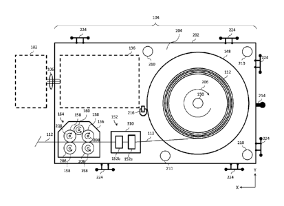
14
Date Recue/Date Received 2021-10-05
Ref. No. 68673-CA
disable a welding operation when an amount of wire remaining in the wire spool
148 is less
than a threshold amount.
100641 In some examples, the welding wire source 114 includes a sensor 162
to determine
an amount of wire remaining in the wire spool 148. For example, the sensor 162
may be a scale
to measure the weight of the wire spool 148. Signals from the scale (sensor
162) are fed back
to the control circuit 144 such that the control circuit 144 can track a
consumption of welding
wire by weight. As described above, the operator interface 142 may display an
amount of wire
remaining in the wire spool 148 (e.g., by weight or length) and/or indicate
when an amount of
wire remaining in the wire spool 148 is less than a threshold amount. In some
examples, the
control circuit 144 may send a command to stop or disable a welding operation
when an amount
of wire remaining in the wire spool 148 is less than a threshold amount. In
some examples,
rather than a scale, the sensor 162 may be a light sensor which measures
approximately how
much wire is left in the spool. In some examples, a light sensor may determine
when an amount
of wire remaining on the spool is less than a threshold amount. In some
examples, multiple
light sensors may be used to determine when the amount of wire remaining is at
various
threshold amounts.
100651 In some examples, the wire-feeder system 104 may include a sensor
162 that detects
when a welding wire source 114 is connected to the wire-feeder system 104. For
example, the
sensor 162 may be a radio frequency identification (-RFID") reader which reach
a RFID tag
on the wire spool 148. The RFID reader may receive information about the wire
spool 148, for
example a wire type, wire length, or wire weight. The information is sent to
the control circuit
144. The control circuit 144 may track a consumption of the wire spool 148
based on the initial
information received from the sensor 162 and/or monitoring use of the wire.
The control circuit
144 may adjust one or more settings of the wire-feeder system 104 based on the
wire type
information. The control circuit 144 may also transmit the received wire type
information to
Date Recue/Date Received 2021-10-05
Ref. No. 68673-CA
the power supply 102 (e.g., via the interface circuit 134). The control
circuit 122 of the power
supply 102 may then adjust one or more settings of the power supply 102 based
on the received
wire type. In some examples, the control circuit 144 of the wire-feeder system
104 or the
control circuit 122 of the power supply 102 may determine whether a selected
welding process
or selected weld settings are compatible with the received wire type. In some
examples, the
operator interface (e.g., operator interfaces 120, 142) may indicate that the
received wire type
is not compatible with the selected welding process or selected weld settings.
Other possible
wireless technologies that the sensor 162 may use include Bluetooth, Bluetooth
low energy,
near field communication, ZigBee, RuBee, or the like.
100661 As illustrated, the wire-feeder system 104 includes an external wire
guide assembly
152 connected between the welding wire source 114 and the inlet of the drive
roll assembly
164. The external wire guide assembly 152 guides wire received from the
welding wire source
114 to the wire feed rollers 158. The external wire guide assembly 152 avoids,
or at minimum
mitigates, inlet guide wear issues at the drive roll assembly 164 and improves
longevity of the
drive roll assembly 164 by presenting welding wire 112 without the added side
loads and force
that are presented by heavy wire on a large wire spool 148. While the external
wire guide
assembly 152 will be primarily described in connection with a horizontally-
mounted wire spool
148, it can alternatively be used with vertically mounted spools and drive
assemblies.
100671 Figures 2a and 2b illustrate, respectively, top plan and side
elevation views of an
example implementation of the welding-type system 100 of Figure 1. As
illustrated, the wire
feed controller 136, drive roll assembly 164, external wire guide assembly
152, and wire spool
148 may be positioned on a base platform 202. The base platform 202 may be
generally planar
to define a horizontal surface 204 to which the various components are
attached, such as the
wire feed controller 136, drive roll assembly 164, external wire guide
assembly 152, and wire
spool 148.
16
Date Recue/Date Received 2021-10-05
Ref. No. 68673-CA
100681 Unlike traditional wire-feeder systems, each of the wire spool 148
and drive roll
assembly 164 are mounted horizontally on the horizontal surface 204. For
example, wire spool
148 is mounted to the horizontal surface 204 of the base platform 202 and
configured rotate
about a spool axis of rotation 206 via the spool hub 150. As illustrated, the
spool axis of rotation
206 is substantially perpendicular to the horizontal surface 204. Mounting the
wire spool 148
horizontally also allows for a lower provide, single component wire spool
cover. For example,
the wire spool cover may be shaped as a short cylinder (e.g., the height being
dictated by height
of the wire spool 148 in the Z-direction) with an open end to allow the wire
spool cover to fit
over and enclose the wire spool 148.
100691 While the spool axis of rotation 206 is illustrated as 90 degrees
relative to the
horizontal surface 204, those of skill in the art would appreciate that the
spool axis of rotation
206 may not be exactly 90 degrees, rather, the spool axis of rotation 206 can
deviate from the
90 degrees. To that end, in one example, the spool axis of rotation 206 may be
mounted at an
angle that is between 45 and 90 degrees. In another example, the spool axis of
rotation 206 may
be mounted at an angle that is between 80 and 90 degrees relative to the
horizontal surface 204.
In yet another example, the spool axis of rotation 206 may be mounted at an
angle that is
between 85 and 90 degrees relative to the horizontal surface 204.
100701 A horizontally-mounted wire spool 148 works in conjunction with the
external wire
guide assembly 152 to improve wire feeding of large wire spools. For example,
a horizontally-
mounted wire spool 148 improves the weight distribution of the wire-feeder
system 104 with
the wire spool 148 loaded, thus improving the weld operator's ability to move
the wire-feeder
system 104 around the job site to a welding location, whether via a cart,
sled, power source,
etc. Weight distribution also improves a crane's ability to lift the wire-
feeder system 104, as
well as proving storage of the wire-feeder system 104 with a more compact
design with a lower
center of gravity. A low center of gravity enable use of a very low and
compact transportation
17
Date Recue/Date Received 2021-10-05
Ref. No. 68673-CA
sled on slides to allow for improved mobility, safety, and use on multiple
surfaces and job sites.
A horizontal feeder concept coupled with the external wire guide assembly 152
also facilitates
a quick change single touch wire spool change.
100711 In some examples, the wire spool 148 may be locked in place on the
spool hub 150.
For example, a locking mechanism may prevent the wire spool 148 from spinning
on the spool
hub 150 (e.g., which may occur without a locking mechanism when the welding
wire source
114 is moved) except for when an operator manually feeds wire through the
guide 152 or when
the drive components of the feeder pull the wire through the guide 152.
100721 The drive roll assembly 164 includes one or more sets of drive
rollers 158
configured to drive welding wire 112 from the wire spool 148, through the wire
guide assembly
152, and to a welding torch 118. As illustrated, each of the drive rollers 158
is configured to
rotate about a roller axis of rotation 208 that is substantially perpendicular
to the horizontal
surface 204.
100731 The components of the wire feed controller 136, drive roll assembly
164, external
wire guide assembly 152, and wire spool 148 may be modular to enable the
operator to quickly
replace components in the event a malfunction occurs. In other aspect, a
modular configuration
enables an operator to use or repurpose an existing device as the base
platform 202. For
example, a wooden pallet may be used as the base platform 202, if desired.
Further, a modular
configuration allows disassembly or removal of components without disassembly
the entire
system. For example, the drive assembly or portions thereof can be removed
while leaving the
motor in place. As a result, a larger motor can be used and replaceable parts
can be installed
with the motor in situ.
100741 The external wire guide assembly 152 is configured to guide wire
from the wire
spool 148 to the outlet. In some examples, the wire guide assembly 152 is
configured to guide
wire having a diameter that is between 1/16 and 1/8 inches. In some examples,
the wire guide
18
Date Recue/Date Received 2021-10-05
Ref. No. 68673-CA
assembly 152 is configured to guide 3/32 or 1/8 inch wire. As will be describe
below, the
illustrated wire guide assembly 152 comprises a first guide feature 152a
having a first wire
pass-through 302a and a second guide feature 152b having a second wire pass-
through 302b.
Each of the first guide feature 152a and the second guide feature 152b are
coupled to a guide
base 310 and configure to extend upward from the horizontal surface 204. While
a guide base
310 is illustrated, the first guide feature 152a and the second guide feature
152b may be coupled
directly to the horizontal surface 204, thereby obviating the need for a guide
base 310.
100751 While the first guide feature 152a and the second guide feature 152b
are illustrated
as rectangular prisms shaped to define the first and second wire pass-throughs
302a, 302b,
other shapes are completed, such as cylindrical features, a rectangular frame,
a flat panel with
a pass-through, or the like. As illustrated, the first guide feature 152a is
positioned between the
wire spool 148 and the second guide feature 152b. In this arrangement, the
first guide feature
152a serves as the inlet to the external wire guide assembly 152 and the
second guide feature
152b serves as the outlet to the external wire guide assembly 152.
100761 Figure 3a illustrates a front perspective view (the inlet side) of
the wire guide
assembly 152, while Figure 3b illustrates a rear perspective view (the outlet
side) of the wire
guide assembly 152 according to a first aspect. Figure 3c illustrates a cross-
sectional side view
of an example wire guide assembly 152 according to a second aspect, where the
wire guide
assembly 152 has a tapered wire pass-through 302c (e.g., shaped as a conical
frustum). In either
example, the wire guide assembly 152 may be rounded or beveled at its edges
314 to reduce
friction and/or scraping of the welding wire 112 as it passes through the wire
pass-through. In
other aspects, the wire guide assembly 152 may include bearings (e.g., ball
bears) or similar
devices to reduce friction between the welding wire 112 and the wire guide
assembly 152 (e.g.,
at the wire pass-through).
19
Date Recue/Date Received 2021-10-05
Ref. No. 68673-CA
100771 In certain aspects, the first guide feature 152a and the second
guide feature 152b
may be modular to enable easy replacement or adjustment of one or both guide
features 152a,
152b in the event of damage, wear and tear, etc. For example, the first guide
feature 152a (as
an inlet) may experience greater wear and tear than the second guide feature
152b (as an outlet),
thus it may be advantageous (e.g., more cost efficient) to replace just the
first guide feature
152a. To that end, the first guide feature 152a and the second guide feature
152b may be
removably coupled to the wire guide assembly 152 or the base platform 202. For
example, the
first guide feature 152a and the second guide feature 152b may be removably
coupled to the
guide base 310 or directly to the horizontal surface 204 of the base platform
202 via one or
more mechanical fasteners 112, such as screws, bolts, clips, snaps, etc.
Further, the first guide
feature 152a and the second guide feature 152b may be repositioned relative to
one another to
accommodate a particular wire guide path. In one example, the guide base 310
(or horizontal
surface 204) may including multiple attachment points to enable the user to
adjust the spacing
and/or angle between the first guide feature 152a and the second guide feature
152b or position
relative to the drive roll assembly 164 or the wire spool 148.
100781 As illustrated in Figure 3a and 3b, the first wire pass-through 302a
may be larger
than the second wire pass-through 302b. In operation, the larger first wire
pass-through 302a
helps to guide the welding wire 112 as the wire unspools toward the smaller
second wire pass-
through 302b. As can be appreciated, the welding wire 112 moves laterally as
it unspools from
the wire spool 148. A larger first wire pass-through 302a helps to reduce wear
at the first point
of contact of the external wire guide assembly 152, while also helping to
control and guide the
welding wire 112 toward the second wire pass-through 302b. The second wire
pass-through
302b, in turn, further restricts the lateral movement of the welding wire 112
before passing the
welding wire 112 to the drive roll assembly 164. In lieu of two separate guide
features, a single
guide feature may be provided with a single wire pass-through, for example, as
illustrated in
Date Recue/Date Received 2021-10-05
Ref. No. 68673-CA
Figure 3c. As illustrated, the guide feature may define a wire pass-through
(e.g., a tunnel) that
is tapered from the inlet 312a to the outlet 312b. In this example, the larger
end of the tapered
wire pass-through 302c serves the function of the inlet 312a, akin to the
first wire pass-through
302a, while the smaller end of the single wire pass-through serves the
function of the outlet
312b, akin to the second wire pass-through 302b.
100791 Referring back to Figures 2a and 2b, the base platform 202 may be
fabricated form
metal, wood, plastic, composites, or a combination thereof. In certain
aspects, the base platform
202 may be a repurposed structure, such as a wooden pallet. The topside (i.e.,
the horizontal
surface 204) and underside are preferable planar (i.e., flat) to enable
stacking, loading, and ease
of portability.
100801 The base platform 202 may comprises a plurality of supports 210 to
support a
second wire-feeder system 104b above the horizontal surface 204 of a first
wire-feeder system
104a. Each of the plurality of supports 210 may be shaped as a column, post,
block, or the like
and can be fabricated from metal, wood, plastic, composites, or a combination
thereof. The
height of the plurality of supports 210 may be dictated by the height of the
tallest object
mounted to the horizontal surface 204, thereby ensuring proper clearance when
a second wire-
feeder system 104b is stacked on the first wire-feeder system 104a. The
plurality of supports
210 may comprise at least three supports 210 to support a base platform 202 of
the second
wire-feeder system 104b, but additional supports 210 may be provided (e.g.,
one at each corner
of the base platform 202).
100811 As a result of this configuration, the wire-feeder system 104 may be
configured to
easily stack (e.g., multiple wire-feeder system 104 can be stacked on top of
each other).
Stacking the wire-feeder systems 104 minimizes space taken up by the multiple
wire-feeder
systems 104 thereby enabling a job site to preserve valuable floor space
without sacrificing
production. Stacking the wire-feeder systems 104 also allows for welding
operation to continue
21
Date Recue/Date Received 2021-10-05
Ref. No. 68673-CA
when a wire spool 148 is depleted by allowing the operator to switch wire-
feeder systems 104
while a spool is replaced. In some examples, an operator may have multiple
wire-feeder
systems 104, and can quickly replace one wire-feeder system 104 with another
wire-feeder
system 104 in the event of a malfunction or when the wire spool 148 is spent.
100821 By way of illustration, Figure 4 illustrates an example where three
wire feeders
systems (illustrated as a first wire-feeder system 104a, a second wire-feeder
system 104b, and
a third wire-feeder system 104c) are stacked on top of one another, where the
bottom-most first
wire-feeder system 104a further comprises a plurality of wheels 212.
Similarly, Figure 5
illustrates an example where two wire feeders (illustrated as a first wire-
feeder system 104a
and a second wire-feeder system 104b) are stacked on a hand cart 502 (or other
wheeled or
mobile structure, such as a dolly, sled, vehicle, portable power source,
etc.). In the illustrated
example, the second wire-feeder system 104b can be lowered onto the first wire-
feeder system
104a via a cable 506 (or a rope).
100831 In operation, an operator can quickly switch from one wire source to
another wire
source (e.g., disconnect one wire-feeder system 104 from the power supply 102
and connect a
different wire-feeder system 104). In some examples, different wire sources 15
may include
different wire types (e.g., wire size or wire material). For example, an
operator may have two
or more wire-feeder systems 104, each with a different type of welding wire
112. Various
welding operations may require the use of a different wire type. For example,
one operation
may require 1/8 inch wire while a second operation may require 3/32 inch wire.
An operator
may connect the wire-feeder system 104 including the appropriate wire type for
the particular
operation to the power supply 102. Then, when the operator performs a
different second
welding operation that requires a different wire type, the operator can
disconnect the first wire-
feeder system 104a from the wire feeder and connect a second wire-feeder
system 104b that
includes the appropriate wire type for the second welding operation.
22
Date Recue/Date Received 2021-10-05
Ref. No. 68673-CA
100841 To increase mobility, the base platform 202 may comprise a plurality
of wheels 212
(e.g., casters, which may include a braking function, directional wheel lock,
etc.) on the
underside (i.e., the surface opposite the horizontal surface 204) to allow the
base platform 202
to move across a surface 222 (e.g., the ground, floor, etc.). While wheels 212
are illustrated,
other devices are contemplated depending on the type of surface 222, such as
skids, floats, etc.
In another aspect, one or more wire-feeder systems 104 may instead be stacked
and/or mounted
to (or otherwise ported by) a hand cart 502, which may include a push/pull
handle 504. The
push/pull handle 504 may be removable from hand cart 502 or foldable to
facilitate compact
storage. In certain aspects, the wire-feeder systems 104 may include carrying
handles 224. For
example, as illustrated in Figure 2a, the carrying handles 224 may be
positioned at the edges
or on the sides of the base platform 202 and may be spaced around the base
platform 202 to
enable for two or more people to carry it. An example of which is illustrated
in Figure 5, where
the second wire-feeder system 104b is shown in broken lines. The base platform
202 may
further include a tow coupler 214 (illustrated as a trailer hitch with a ball)
to enable attachment
of a wheeled base platform 202 to a vehicle or another base platform 202
(e.g., as part of a
train).
100851 The base platform 202 may further comprises a set of forklift
pockets 218 to enable
a fork lift to readily transport and/or stack the wire-feeder systems 104. In
some example, each
side of the base platform 202 may comprises a set of forklift pockets 218 to
enable the fork lift
to approach and lift the wire-feeder system 104 from any direction.
100861 In some examples, the base platform 202 comprises one or more hoist
attachments
216 (e.g., rings, shackles, etc.) to enable the base platform 202 to be
suspended by a crane or
other hoist via a cable 506. The hoist attachment(s) 216 may be positioned
such that the base
platform 202 is level relative to the surface 222 when suspended via the cable
506 (e.g., at the
center of gravity in the X-Y plane so as to avoid tipping).
23
Date Recue/Date Received 2021-10-05
Ref. No. 68673-CA
100871 Figure 6 illustrates an example method 600 for configuring a wire-
feeder system
104 in a welding-type system 100. At step 602, a wire spool 148 is mounted to
a horizontal
surface of a base platform such that the wire spool 148 is configured to
rotate about a spool
axis of rotation 206 that is perpendicular to the horizontal surface. At step
604, welding wire
112 is passed from the wire spool 148 to a wire guide assembly 152 that is
separate from the
wire spool 148. At step 606, the welding wire 112 is driven from the wire
guide assembly 152
to a welding torch 118 via a drive roll assembly 164 having one or more sets
of drive rollers
158. At step 608, a second wire-feeder system 104b is stacked on top of the
wire-feeder system
104a. The second wire-feeder system 104b may be supported by, for example,
supports 210 on
the wire-feeder system 104a.
100881 While the present method and/or system has been described with
reference to
certain implementations, it will be understood by those skilled in the art
that various changes
may be made and equivalents may be substituted without departing from the
scope of the
present method and/or system. In addition, many modifications may be made to
adapt a
particular situation or material to the teachings of the present disclosure
without departing from
its scope. For example, block and/or components of disclosed examples may be
combined,
divided, re-arranged, and/or otherwise modified. Therefore, the present method
and/or system
are not limited to the particular implementations disclosed. Instead, the
present method and/or
system will include all implementations falling within the scope of the
appended claims, both
literally and under the doctrine of equivalents.
24
Date Recue/Date Received 2021-10-05