Note: Descriptions are shown in the official language in which they were submitted.
CA 03133454 2021-09-13
WO 2020/190836
PCT/US2020/022898
BATTERY PACK
Cross-Reference to Related Applications
[0001] This application claims priority to US Provisional Patent
Application Serial
No. 62/818,851, filed March 15, 2019, titled BATTERY PACK, the entirety of
which is
hereby incorporated by reference herein.
Field of the Invention
[0002] The present invention relates to batteries. More particularly,
the present
invention relates to a battery pack that can be used interchangeably with a
variety of devices.
Back2round of the Invention
[0003] Technology has become increasingly intertwined with our daily
lives, where
we use technology for both communication and comfort. However, in order to use
those
technological devices, those technological devices require a power source to
function.
While indoors, lights, air condition, and other technological devices are
either already built
into the building or can be plugged into a wall socket. However, it is
generally not possible
to simply plug in while outdoors due to the lack of a power source. While
extension cords
and batteries allow people to use their devices outdoors, they both have their
disadvantages.
[0004] Extension cords may extend the area where the device may be used,
but
extension cords still require the device to be plugged into a wall socket
thereby restricting
where the user may use their devices. Batteries, on the other hand, allow the
devices to be
portable. However, disposable batteries create waste and do not produce
sufficient power to
run some devices. Other times, a rechargeable battery may only be compatible
with one
1
CA 03133454 2021-09-13
WO 2020/190836
PCT/US2020/022898
specific device. It is therefore desirable for a battery able to produce
enough power to allow
a variety of devices to run, as well as being compatible with several
different devices.
[0005] Due to the heat and humidity, people often desire a method to
cool
themselves. Fans can generate a breeze which can help people feel cooler.
Fans, however,
are generally plugged into a wall socket, thereby restricting where they can
be used. Other
fans are small portable fans that use disposable batteries, and are only
capable of generating
a small breeze. It is therefore desirable for a fan to be portable and capable
of generating a
strong breeze. In addition to fans, flashlights, fluid pumps, and Bluetooth
speakers all
require power sources. Many must be plugged into a wall socket, or require
disposable
batteries or a specific rechargeable battery. Disposable batteries produce
more waste, while
proprietary rechargeable batteries can be inconvenient. It is therefore
desirable for devices,
such as fans flashlights, fluid pumps, and Bluetooth speakers to all be
compatible with the
same rechargeable battery.
[0006] Millions of people go camping every year, and "glamping" is
becoming more
popular with people who want to enjoy the comforts of home, while still being
outdoors.
People may want light and air conditioning while camping. Further, campers
also often
bring their technological devices (e.g., a cell phone), which may run out of
power.
Therefore, it is desirable for a tent that contains both lighting and cooling
systems, and/or is
able to charge technological devices.
[0007] Similarly, people also bring their technological devices, which can
run out of
power, while using shelters. In addition to the lack of charging stations in a
typical shelter,
there can be hundreds of tents set up at large events, making it difficult to
identify an
individual shelter at a distance. Therefore, it is desirable for a shelter to
be able to charge
technological devices and be readily identifiable from a distance.
2
CA 03133454 2021-09-13
WO 2020/190836
PCT/US2020/022898
Summary of the Invention
[0008] The present invention provides a battery that can be
interchangeably used with
a variety of technological devices. The battery includes a first battery
section located and
positioned at the first battery end, and a second battery section located and
positioned at the
.. second battery end. The first battery section includes a first battery
section face, which as a
first flap, a second flap, and a middle section. The first flap and second
flap may each be
selectively lifted to expose at least one USB-A port and/or USB-C port
underneath. The
USB ports may be used to charge technological devices that are connected to
the USB port
through a USB plug or to recharge the battery. The battery may include at
least one
indicator to signal the amount of power and/or if the battery is charging. The
middle section
may further include a light source, which may serve as a flashlight.
[0009] The second battery section includes at least one prong that
allows the battery
to selectively engage with a charging station to recharge the reusable
battery. The charging
station includes a central cavity for receiving the battery, where the battery
can be inserted
.. into the central cavity and engage the charging station. The battery may
also be inserted into
various technological devices to power those devices, allowing those devices
to be used
without a required specific battery. For example, the battery may be used with
fans,
lanterns, tents ¨ including lighting a tent as well as cooling a tent,
flashlights, Bluetooth
speakers, fluid pump, and light source within a shelter.
Brief Description of the Drawin2s
[0010] Fig. 1 is a perspective view of an example embodiment of a
battery;
[0011] Fig. 2 is a perspective view of the battery of Fig. 1, with
certain elements
removed to show elements thereunder;
3
CA 03133454 2021-09-13
WO 2020/190836
PCT/US2020/022898
[0012] Fig. 3 is a perspective view of the battery of Fig. 1 engaged
with an example
embodiment of a charging station;
[0013] Fig. 4s atop plan view of the charging station and battery of
Fig. 3;
[0014] Fig. 5 is a perspective view of an example embodiment of a fan;
[0015] Fig. 6 is a perspective view of an example embodiment of a lantern;
[0016] Fig. 7 is a perspective view of an example embodiment of a
flashlight;
[0017] Fig. 8 is a perspective view of an example embodiment of a
fluid pump;
[0018] Fig. 9 is an elevation view of the fluid pump of Fig. 8;
[0019] Fig. 10 is a perspective view of an example embodiment of a
Bluetooth
speaker engaged with a battery;
[0020] Fig. 11 is a perspective view of an example embodiment of a
tent with a
ground vent and a peak vent;
[0021] Fig. 12 is an enlarged perspective view of the ground vent
embodiment of
Fig. 11;
[0022] Fig. 13 perspective view of another example embodiment of a tent
with a
ground vent;
[0023] Fig. 14 is an enlarged perspective view of the peak vent
embodiment of Fig.
11;
[0024] Fig. 15 is a perspective view of another example embodiment of
a tent with a
lighting system;
[0025] Fig. 16 is a perspective view of an interior portion of the
tent of Fig. 15;
[0026] Fig. 17 is an elevation view of an example embodiment of a
control panel in a
tent;
[0027] Fig. 18 is an elevation view of an example embodiment of a
storage pouch and
a USB outlet;
4
CA 03133454 2021-09-13
WO 2020/190836
PCT/US2020/022898
[0028] Fig. 19 is a perspective view of an example embodiment of a
shelter; and
[0029] Fig. 20 is a perspective view of an example embodiment of
control panel of
for the shelter of Fig. 19.
Detailed Description of the Invention
[0030] The invention will now be described with reference to the
drawing figures, in
which like reference numerals refer to like parts throughout. For purposes of
clarity in
illustrating the characteristics of the present invention, proportional
relationships of the
elements have not necessarily been maintained in the drawing figures.
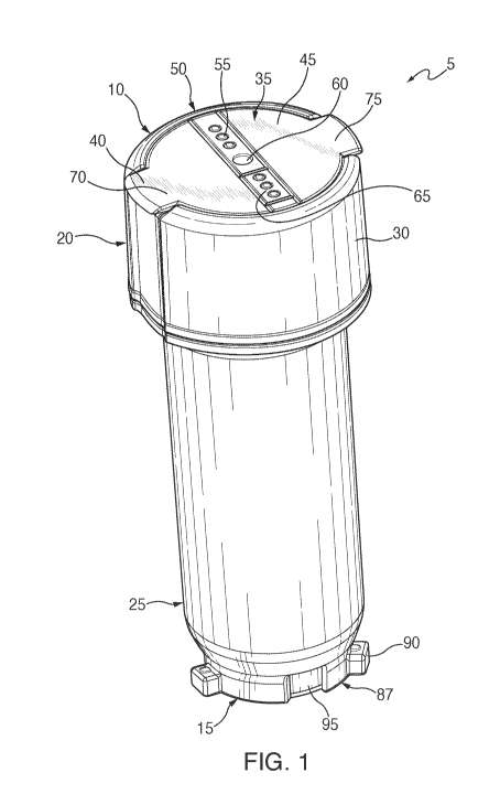
[0031] As illustrated in Fig. 1, a battery 5 includes a first battery end
10 and a second
battery end 15. The battery 5 preferably includes a first battery section 20
and a second
battery section 25. The first battery section 20 is preferably located and
positioned at the first
battery end 10. The second battery section 25 extends from the first battery
section 20 to the
second battery end 15. The first battery section 20 may have a larger width
than the second
.. battery section 25.
[0032] The first battery section 20 includes a first battery section
sidewall 30 and a
first battery section face 35. The first battery section sidewall 30 extends,
from the second
battery section 25 to the first battery section face 35. The first battery
section face 35 is
positioned at the first battery end 10, and may have a first flap 40, a second
flap 45, and a
middle section 50.
[0033] In one embodiment, the middle section 50 may be a narrow band
that extends
across the first battery section face 35, and is further located and
positioned substantially
along the diameter of the first battery section face 35. The middle section 50
may include at
least one indicator 55, which may be embodied as an LED (light emitting
diode). The at least
one indicator 55 may signal to a user the amount of power remaining in power
storage
5
CA 03133454 2021-09-13
WO 2020/190836
PCT/US2020/022898
elements of the battery 5 and/or if the battery 5 is charging or is charging
another device, as
will be explained in more detail hereinafter. The power storage elements (not
shown) may be
lithium-ion storage elements or the like, as would be understood. The middle
section 50 may
further include a light source 60 that allows the battery 5 to be used as a
flashlight. However,
.. in other embodiments, the light source 60 may be located and positioned
elsewhere on the
battery S.
[0034] The indicator(s) 55 and the light source 60 are in electronic
communication
with a printed circuit board (PCB) (not shown). The PCB may include resistors,
controllers,
and other electronic and data components that may be required to operate
and/or control the
battery S. The PCB is also in electronic communication with a power source
(not shown).
The power source can provide power to the indicator 55, light source 60, and a
device
plugged into the battery 5, and the PCB may read when the indicator 55, light
source 60, or
device is being powered and/or when power should be provided to the indicator
55, light
source 60, or device. A button 65 may also be provided for activating the
light source 60.
[0035] Turning back to Fig. 1 and as stated previously, the first battery
section 20 of
the battery 5 includes the first flap 40 and the second flap 45, located and
positioned on
opposite sides of the middle section 50. The first flap 40 and the second flap
45 are each
shown in Fig. 1 as semicircular in shape, mirroring one another on either side
of the middle
section 50. The first flap 40 includes a first tab 70 and the second flap 45
includes a second
tab 75, which extend from the first flap 40 and second flap 45, respectively,
opposite the
middle section 50.
[0036] The first and second tabs 70, 75 are preferably located and
positioned along
the circumference of the first battery section face 35. The first and second
tabs 70, 75 may be
used to hingedly lift the first and second flaps 40, 45, respectively. Lifting
the first and
.. second flaps 40 and 45 exposes the area of the first battery section face
35 underneath the
6
CA 03133454 2021-09-13
WO 2020/190836
PCT/US2020/022898
first and section flaps 40 and 45. In alternative embodiments, however, either
or both of the
flaps 40 and 45 may instead be removable from the battery 5.
[0037] In one embodiment, proximate the second battery end 15, the
second battery
section 25 includes a main charging and re-charging section 87. This section
87 may include
at least one prong 90 for helping to selectively secure the battery 5 into a
charging station or
a product. Other securing structures are also envisioned. The section 85
further includes
electrical contacts for receiving power from a charging station, or providing
power to a
product.
[0038] In yet another embodiment, the battery 5 may not include a main
charging and
recharging section 87 or at least one prong 90, but may instead only include
the electrical
contacts 95. The contacts 95 may be substantially similar to the at least one
contact of the
charging station 85. The contacts 95 may be located and positioned elsewhere
on the battery
5, as appropriate.
[0039] As can be seen in Fig. 2 in which the flaps 40 and 45 have been
removed, the
flaps 40 and 45 cover and protect a first charging port 85 and a second
charging port 80. The
first charging port 85 may be a Universal Serial Bus-A (USB) port 85, and the
second
charging port 80 may be a USB-C port 80. The first and second charging ports
80 and 85
will be referred to herein as USB-A port 85 and USB-C port 80 for ease of
reference,
although other types of charging ports are envisioned. A device may be
connected to a USB
cable (not shown), and the USB cable may then be plugged into the USB-A port
85. The
device may thereby be powered via the USB-A port instead of the main charging
and
recharging section 87. Alternatively, a power source may be connected to a USB-
C cord (not
shown), and the USB-C cord may then be selectively plugged into the USB-C port
80, which
allows the battery 5 to be charged therethrough, instead of via the electrical
contacts 95. The
battery 5 therefore is able to power various technological devices in multiple
ways, as a
7
CA 03133454 2021-09-13
WO 2020/190836
PCT/US2020/022898
battery or as a battery pack. The same is true for charging the battery 5. In
alternative
embodiments, the first battery section face 35 may have different types of USB
ports.
[0040] As illustrated in Fig. 3, the battery 5 may be inserted into a
charging station
105. The charging station 105 preferably includes at least one cavity 110,
each for receiving
.. a battery 5. Each cavity 110 is therefore shaped and sized so a battery 5
can selectively
engage and mate with the charging station 105. As shown in Fig. 3, the
charging station 105
may include multiple cavities 110 so that more than one battery 5 may be
charged at the same
time.
[0041] In the embodiment of Fig. 4, the cavity 110 may include at
least one prong
groove 115. The at least one prong groove 115 is shaped and sized so that the
at least one
prong 90 of the battery 5 may selectively engage with the at least one prong
groove 115.
Once received by a prong groove 115, the battery 5 may be twisted and the
prong 90 may
move within a track 120 in the charging station 120. Such rotation may also
bring the
contacts 95 of the battery 5 into engagement with corresponding electrical
contacts 125 of the
charging station 105. Once engaged and the charging station 105 is plugged
into a wall
socket, the battery 5 may be charged via contacts 95, 125 so that it can power
other devices.
Figs 3 and 4 illustrate a two-socket charger, with one socket empty. Other
numbers of
sockets may be provided for the charging station 105. Thus, a battery 5 may be
charged via
its electrical contacts 95, or via the USB-C port 80. The battery 5 may
discharge through its
electrical contacts 95, or through the USB-A port 85. It therefore can act as
a rechargeable
battery or as an external battery pack. It may also be daisy-chained with
other batteries 5, by
connecting the USB-A port 85 on one battery 5 to the USB-C port 80 on another
battery 5.
This can be done with as many batteries 5 in series as desired.
[0042] As seen in Fig. 5, a fan 200 includes a fan mount 205 with a
first fan mount
end 210 and a second fan mount end 215. The fan mount 205 as shown has a
circular cross
8
CA 03133454 2021-09-13
WO 2020/190836
PCT/US2020/022898
section, but may have other cross sectional shapes in alternative embodiments.
The fan
mount 205 is adjacent to and abuts a fan hinge 216 at the first fan mount end
210. The fan
hinge 216 preferably allows the fan 200 to rotate. The fan hinge 216 is
adjacent to and abuts
a protective guard 220. The protective guard 220 is preferably a cage-like
structure that
.. surrounds standard fan components, such as a motor and blades.
[0043] The second fan mount end 215 of the fan mount 205
includes a fan
central cavity 225. The fan central cavity 225 is preferably a cavity at the
second fan mount
end 215 that extends into the fan mount 205 and towards the first fan mount
end 210. The
fan central cavity 225 is shaped and sized so that a battery 5 may be inserted
within. The fan
central cavity 225 is preferably substantially similar to the cavity 110 of
the charging station
105. Therefore, depending on the embodiment of the battery 5, the fan central
cavity 240
may include at least one fan prong groove (not shown), substantially similar
to the prong
groove 115 of the cavity 110, as well as corresponding electrical contacts for
receiving power
from the battery 5.
[0044] In addition to, or concurrently with providing power to the fan 200,
the battery
5 may also charge or power another device through its USB-A port 85, or
receive additional
power via its USB-C port 80. The battery 5 can also be removed so that the
battery 5 may be
recharged or may be removed so that the battery 5 may be used with another
device.
[0045] The second fan mount end 215 of the fan mount 205 is preferably
adjacent to
.. and abuts a fan leg connector section 246. In one embodiment, the fan leg
connector section
246 engages the fan mount 205. The fan leg connector section 246 further
includes at least
one fan leg groove 248. The fan leg groove 248 may be a U-like groove shaped
and sized so
that at least one fan leg 250 may fit within the fan leg groove 248.
[0046] The at least one fan leg 250 projects away from the fan mount
205. The at
least one fan leg 250 is preferably pivotally connected to the fan leg
connector section 246.
9
CA 03133454 2021-09-13
WO 2020/190836
PCT/US2020/022898
The shape of the fan leg groove 248 and the pivoting engagement preferably
allows the fan
leg 250 to bend or fold. The at least one fan leg 250 may fold upwards so that
when the fan
legs 250 are folded, the fan legs 250 are adjacent to the fan mount 205. The
fan 200 may
therefore be folded so that the fan 200 is more portable. The second fan mount
end 215 of
the fan mount 205 may further include a fan ring which allows the fan 200 to
be hung upside
down from a surface, such as a ceiling, roof, or other structure.
[0047] As seen in Fig. 6, the battery 5 may also be inserted into a
first embodiment of
a lantern 300, as will be explained in more detail hereinafter. The first
embodiment of the
lantern 300 may include a first lantern end 302 and a second lantern end 304,
with a lantern
base 306 located and positioned at the second lantern end 304. The base 306
may include a
first base face 308 and a second base face 310. The second base face 310 is
adjacent to and
abuts a surface (e.g. table, ground, or ledge) when the lantern 300 is placed
on the surface.
A globe 314 extends from the first base face 308. The globe 314 is preferably
transparent or
translucent.
[0048] A heat sink 318 has a first heat sink end 320 and a second heat sink
end 322.
The heat sink 318 may include a slotted portion 324 preferably located and
positioned above
the globe 314. The slotted portion 324 preferably includes at least one slot
326 for air flow
purposes. The heat sink 318 is adjacent to and abuts a light source 328. The
light source
328 is located and positioned within the globe 314, and extends downwardly
from the heat
sink 318. Thus, the light source 328 is suspended from the top of the lantern
300.
[0049] A top portion 330 of the lantern 300 preferably has a top face
332 and a top
sidewall 334 circumscribing the top face 332. The top portion 330 may extend
from the heat
sink 318. The top portion 330 preferably includes at least two top portion
apertures 336 that
extend through the top sidewall 334. A pair of top portion apertures 336 are
preferably
located and positioned on opposite sides of the top sidewall 334. The top
portion apertures
CA 03133454 2021-09-13
WO 2020/190836
PCT/US2020/022898
336 are shaped and sized so that a handle 338 may extend into and through the
top portion
apertures 336. In one embodiment, the top portion 330 has two top portion
apertures 336
and a curved half circle shaped handle 338, which includes a hook (not shown)
at both ends
of the handle 338, may be inserted into the top portion apertures 336 and used
to secure the
handle 338 to the top portion 330. The top portion 330 further includes a top
portion
aperture (shown with a battery 5 installed therein). The top portion aperture
is preferably
located and positioned in the center of the top portion 330 and also extends
through the top
portion 330. The top portion aperture may have the same structure as any other
battery
receptacle discussed herein.
[0050] Once the battery 5 has been selectively inserted into the lantern
central cavity,
the battery 5 may act as a power source and provide power to the first
embodiment of the
lantern 300. The lantern 300 may further include a dial or control switch 344.
In one
embodiment, the control switch 344 is located and positioned on the top
portion 330 of the
lantern 300. The control switch 344 may turn the light source 328 on or off,
as well as
controlling the brightness of the light source 328.
[0051] Other lantern-style embodiments are also envisioned. For
example, lanterns in
which the battery 5 is inserted from below, with corresponding light sources
extending up
from the bottom, rather than down from the top. may be used.
[0052] In addition to the fan 200 and various embodiments of the
lantern 300, the
battery 5 may further be compatible with a flashlight 400, shown in Fig. 7.
The flashlight
400 may have a first flashlight end 405 and a second flashlight end 410. The
flashlight 400
further includes a flashlight housing 415 that has a first flashlight housing
section 420 and a
second flashlight housing section 425. The first flashlight housing section
420 is located at
the first flashlight end 405, while the second flashlight housing section 425
is located at the
second flashlight end 410. The first flashlight housing section 420 is
preferably a cylindrical
11
CA 03133454 2021-09-13
WO 2020/190836
PCT/US2020/022898
member, as is the second flashlight housing section 425. The first flashlight
housing section
420 may have a larger circumference than the second flashlight housing section
425. The
first flashlight housing section 420 includes an LED or bulb (not shown) which
is the light
source for the flashlight 400, and a reflector (not shown) that is preferably
a funnel-like
shape surrounding the LED to form a focused beam of light. The reflector may
be made out
of an aluminum-coated plastic. The first flashlight housing section 420
further includes a
lens 430 that extends over the first flashlight end 405 to prevent the LED
from breaking. A
bezel 435, which may be an annular ring, may be placed over the lens 430 to
secure the lens
430 to the flashlight 400.
[0053] The second flashlight housing section 425 includes a flashlight
battery cavity
440 located and positioned at the second flashlight end 410 and extends
towards the first
flashlight end 405. The flashlight cavity 446 is shaped and sized so that the
battery 5 may be
inserted into the flashlight cavity 440 so that the flashlight 400 may
selectively engage with
the battery S. The battery cavity 440 of the flashlight 400, and all other
such cavities
discussed herein, may have the same structure as any other battery receptacle
discussed
herein.
[0054] When the battery 5 is inserted into the flashlight cavity 440
and selectively
engages with the flashlight 400, a switch 445 may be actuated thereby
completing the
electrical connection causing the flashlight 400 to turn on. In one
embodiment, the switch
445 may have a low light setting and a high light setting. The second
flashlight end 410 may
further include a loop aperture where a string may be inserted into and
through to make a
loop so that a user may insert their hand through the loop to reduce the
possibility of
dropping the flashlight 400.
[0055] Turning to Fig. 8, the battery 5 may further be compatible with
a fluid pump
500. The fluid pump 500 includes a housing 505 that surrounds the components
of the fluid
12
CA 03133454 2021-09-13
WO 2020/190836
PCT/US2020/022898
pump 500. The housing 505 preferably has a first housing end 510 and a second
housing
end 515, as well as a first housing face 520 and a second housing face 525. In
one
embodiment, the housing 505 may be generally circlar with a nozzle 530 located
and
positioned at the first housing end 510. The nozzle 530 may be inserted into
an aperture of
an object that the fluid pump 500 is being used to fill with fluid.
[0056] The housing 505 further includes a first protrusion 535 that
projects away
from the first housing face 520, and a second protrusion 540 that projects
away from the
second housing face 525, illustrated in Figs. 8 and 9. Both the first
protrusion 535 and the
second protrusion 540 may be circular projections. In one embodiment, the
second
protrusion 540 may have a larger circumference than the first protrusion 535.
The first
protrusion 535 includes at least one pump aperture 545 that allows for fluid
intake through
protrusion 535. At the first housing end 510, the housing 505 may also include
a receiver
550 shaped and sized so that an accessory nozzle 555 may be secured within the
indention
550. The accessory nozzle 555 may selectively engage the nozzle 530 when it is
inserted
onto the nozzle 530. When the accessory nozzle 555 is placed onto the nozzle
530, the
accessory nozzle 555 allows the nozzle 530 to be inserted into a smaller
aperture of an
object, where the fluid pump 500 is being used to fill the object with the
fluid, than what
otherwise might not be possible.
[0057] The housing 505 also includes a pump cavity 560, (shown with a
battery 5
installed therein), located and positioned at the second housing end 515 and
extends towards
the first housing end 510. Once the battery 5 has been inserted into the pump
cavity 560, the
battery 5 may provide power to standard components of a fluid pump, such as a
motor and
impeller. The fluid pump 500 may therefore take in fluid through the first
protrusion 535
and/or the second protrusion 540 and pump out the fluid through the nozzle
530. The battery
.. 5 is therefore compatible with several different devices, including the
fluid pump 500.
13
CA 03133454 2021-09-13
WO 2020/190836
PCT/US2020/022898
[0058] In addition to the fluid pump 500, the battery 5 may further be
compatible
with a speaker 600, shown in Fig. 10. The speaker 600 includes a first speaker
end 605 and
a second speaker end 610. The speaker 600 further includes a housing 615,
which may have
a circular cross section. In alternative embodiments, the housing 615 may be
other cross
sectional shapes. The housing 615 includes a speaker cavity 620 that extends
from the first
speaker end 605 towards the second speaker end 610. The speaker cavity 620 is
shaped and
sized so that the battery 5 may be inserted into the speaker cavity 620. When
the battery 5
selectively engages with the speaker 600, the battery 5 provides power to
standard
components of the speaker 600. For example, the housing 615 may further
include various
components such as an amplifier, drivers, and input. For example, the input
may be a
Bluetooth module. These components are all preferably located and positioned
within the
housing 615, surrounding the speaker cavity 620. The speaker may further
include buttons
635 that may turn the speaker 600 on and off, as well as controlling the
volume, and music,
generally. The speaker 600 is powered by the battery 5, which is also
interchangeable or
compatible between other technological devices.
[0059] The battery 5 may also be compatible with a tent 700, as will
be described in
more detail hereinafter. The tent 700 includes at least two tent poles 702,
and tent walls 704,
illustrated in Fig. 11. In one embodiment, the tent poles 702 are preferably
cylindrical
members, and may be hollow to reduce their weight. The at least two tent poles
702 may
further be rigid or bendable. In embodiments when the at least one tent pole
702 is
bendable, the tent poles 702 may be linked together through elastic cords
extending through
the hollow center of the at least two tent poles 702. The tent poles 702 may
be inserted into
the at least one angled joint fitting 703 to connect the tent poles 702 to one
another, forming
the structure of the tent 700.
14
CA 03133454 2021-09-13
WO 2020/190836
PCT/US2020/022898
[0060] The tent 700 may further include a ground sheet (not shown)
that is located
and positioned adjacent to and abuts the ground when the tent 700 has been set
up. The tent
700 further includes at least three tent walls 704, where each tent wall 704
extends between
the at least two tent poles 702 to create a barrier or wall. Each tent wall
704 is preferably
.. adjacent to at least two other tent walls 704 and the ground sheet (not
shown). The tent 700
therefore has a ground sheet (not shown) and at least three tent walls 704
that project
upwards and away from the ground sheet. The at least three tent walls 704
preferably meet
to form a peak 706. Both the ground sheet and tent walls 704 are preferably
waterproof
Other tent structures are also envisioned, as would be understood.
[0061] In one embodiment shown in Fig. 12, the ground sheet and the tent
walls 704
may each include at least one tent loop 708, which is an extra piece of
material that creates a
loop or aperture shaped and sized so that a tent pole 702 may be inserted into
and through
the tent loop 708. In other embodiments, the tent loop 708 may engage a tent
hook 710,
which may be hooked onto the tent poles 702. In yet another embodiment, the
tent hook 710
may be attached directly to the tent wall 704, also allowing the tent wall 704
to engage with
the tent pole 702. The ground sheet and tent walls 704 are therefore able to
selectively
engage the tent poles 702 so that the ground sheet and tent walls 704 may be
stretched or
held between the tent poles 702 to form the structure of the tent 700.
[0062] The tent 700 may further include at least one ground vent 711.
In one
embodiment, the at least one ground vent 711 may be located and positioned at
a comer or
junction of adjacent tent walls 704. In other words, the at least one ground
vent 711 may be
located where two adjacent tent walls 704 abut one another. In one embodiment,
the at least
one ground vent 711 is preferably located closer to the ground sheet rather
than the peak 706
of the tent 700. The ground vent 711 includes a first ground vent flap 714 and
a second
ground vent flap 716. A first side 718 and 720 of the first ground vent flap
714 and the
CA 03133454 2021-09-13
WO 2020/190836
PCT/US2020/022898
second ground vent flap 716, respectively, are adjacent to and abut the tent
wall 704. A
second side 722 and 724 of the first ground vent flap 714 and the second
ground vent flap
716, respectively, are adjacent to and abut each other. The first ground vent
flap 714 and
second ground vent flap 716 are preferably angled, creating an upside V-like
shape. The
ground vent 711 therefore has an opening 725, closer to the ground, which
extends into the
ground vent 711.
[0063] The second sides 722 and 724 of the first ground vent flap 714
and the second
ground vent flap 716 preferably includes a tent hook 710 or tent loop 708
allowing the
ground vent 711 to engage the tent pole 702. When the ground vent 711 has been
attached
to the tent pole 702, the ground vent 711 is preferably pulled towards the
tent pole 702 so
that the ground vent 711 is a triangular pyramid-like shape. The ground vent
711 further
includes a mesh area 726 located and positioned in the area underneath the
first ground vent
flap 714 and the second ground vent flap 716 when the ground vent 711 is
selectively
engaged to the tent pole 702. The mesh area 726 is preferably part of the tent
wall 704, and
is a mesh-like material capable of allowing air circulation. The at least one
ground vent 711
allows air to flow into the tent 700. The ground vent 711 and its opening 725
are preferably
angled and located so that air may flow upwards into the tent 700.
[0064] In another embodiment and as shown in Fig. 13, the ground vent
711 may be
located and positioned on a tent wall 704, instead of at a corner or
intersection of two tent
walls 704. The ground vent 711 may include the first ground vent flap 714, the
second
ground vent flap 716, and a ground vent top 727. The first and second ground
vent flaps 714
and 716 may be triangle-like shapes, while the ground vent top 727 may be a
rectangular-
like shape. The first side 718 of the first ground vent flap 714 and the first
side 720 of the
second ground vent flap 716 are both adjacent to and abut the tent wall 704.
The second
sides 722 and 724 of the first ground vent flap 714 and the second ground vent
flap 716,
16
CA 03133454 2021-09-13
WO 2020/190836
PCT/US2020/022898
respectively, are adjacent to and abut the ground vent top 727. The ground
vent top 727
extends between the first and second ground vent flaps 714 and 716. The ground
vent 711
may be positioned in an extended position, away from the tent wall 704,
through tent poles
702. The first ground vent flap 714, the second ground vent flap 716, and the
ground vent
top 727 preferably create a triangle-like shape that projects away from the
tent wall 704.
The ground vent 711 therefore has an opening 725, closer to the ground. The
ground vent
711 also preferably has a mesh area 726 as part of the tent wall 704, at the
area underneath
the ground vent 711. The mesh area 726 may allow air circulation into the
interior portion
of the tent 700.
[0065] The tent 800 may also include a peak vent 712, shown in Fig. 14.
While the
peak vent 712 may also allow air to flow into the tent, the peak vent 712
preferably allows
air to travel out of the tent as the air currents rise in hot weather. The
peak vent 712
preferably has at least two peak sides 728. The peak vent 712 preferably has
as many peak
sides 728 as there are tent walls 704, but may have a different number of peak
sides 728 in
other embodiments. The peak vent 712, and its peak sides 728, may therefore
extend along
the peak 706. In another embodiment, the peak vent 712 may include two peak
sides 728
that engages and extends or project away from the tent walls 704 or tent loops
708. The
peak sides 728 may be attached to the tent walls 704 or tent loops 708, while
two tent peak
poles 730 preferably engages the peak vent 712 substantially in the center of
the peak 706,
on both sides of the peak 706. The peak vent 712 therefore forms a triangular
shape over the
peak 706 of the tent 700. Other structures for the peak vent are also
envisioned.
[0066] Similarly to the first and second ground vent flaps 714 and
716, the peak sides
728 are preferably made out of the same material as the tent walls 704.
However, in
alternative embodiments, the peak sides 728 may be made out of a different
material or
materials. The area underneath the peak vent 712 is preferably made out of a
mesh-like
17
CA 03133454 2021-09-13
WO 2020/190836
PCT/US2020/022898
material, therefore allowing air to pass through the peak 706. The tent 700
may therefore be
cooler due to the ground vents 711 and peak vent 712 because the cool air can
enter the tent
700 through the ground vent 711 and warm air can exit through the peak vent
712.
[0067] In addition to the ground vents 711 and peak vent 712, the tent
700 may
include at least one light source 732, as shown in Figs. 15 and 16. The at
least one light
source 732 may be located and positioned along the at least one tent pole 702.
The at least
one light source 732 may be further located and positioned in an interior
portion 734 and/or
exterior portion (not shown) of the tent 700. The light source 732 may
therefore provide
light inside of the tent 700 so that people can see while inside the tent 700,
and/or provide
.. light outside of the tent so that people can better see the tent 700 from a
distance or can see
while near the tent 700 due to the light source 732. The tent 700 may further
include a tent
fan 736 in an interior portion 734 of the tent 700, preferably near the peak
706. The tent fan
736 may provide air flow to cool the interior portion 734 of the tent 700.
[0068] Both the light source 732 and the tent fan 736 may be
controlled by a control
panel 738, illustrated in Fig. 16. The control panel 738 is therefore
mechanically and
electronically connected to either or both of the light source 732 and the
tent fan 736. The
control panel 738 may include dials, switches, and/or buttons. The dials,
switches, and/or
buttons may turn the light source 732 and the tent fan 736 on or off, as well
as preferably
controlling the brightness of the light source 732 and the strength of the
wind generated by
the tent fan 736. The control panel 738 may also control the direction of the
wind generated
by the tent fan 736, as well as the speed of the rotation of the tent fan 736
blades.
[0069] The control panel 738, and therefore the light source 732 and
tent fan 736,
may be powered the at least one battery 5. The control panel 738 may include
one or more
battery cavities for receiving one or more batteries, as discussed above. The
control panel
738 may be located and positioned on a tent pole 702, in the interior portion
734 of the tent
18
CA 03133454 2021-09-13
WO 2020/190836
PCT/US2020/022898
700. In yet another embodiment, additionally or alternatively, there could at
least one
additional battery 5 located within a power pack 741, as seen in Fig. 17. The
power pack
741 may include at least one cavity for receiving a battery 5, as discussed
above. The
batteries 5 within the power pack 741 are electronically and mechanically to
the light source
732, tent fan 736, and/or the USB ports 752 to provide power to same. Separate
controls for
each may also be provided, as would be understood.
[0070] Turning to Fig. 18, the tent 700 may further include at least
one storage pouch
748 located and positioned on the tent walls 704. The storage pouches 748 may
include a
storage pouch opening 750 allowing items to be placed within the storage pouch
748. The
tent 700 may also include at least one USB port 752 that may be used to charge
electronic
devices. The USB port 752 is preferably in electronic and mechanical
connection with at
least one battery 5 . The USB port 752 may be located and positioned above a
storage pouch
748 so that the electronic device may be placed within the storage pouch 748
as it is
charging. The battery 5 may therefore be the power source for the light source
732, the tent
.. fan 736, and any electronic devices that are plugged into the USB port to
be charged.
[0071] The battery 5 is preferably further compatible with a shelter
800, shown in
Fig. 19. The shelter 800 includes a frame assembly 805 and a canopy 810. The
frame
assembly 805 includes at least three leg members 815, a truss assembly 820,
and a roof
assembly 825. When the shelter 800 has been assembled, the leg members 815 are
adjacent
to and abut the ground. The leg members 815 extend upwards, and the truss
assembly 820
extends between the leg members 815. The truss assembly 820 preferably allows
for
scissor-like folding for deployment and collapsing of the frame. The roof
assembly 825
preferably also allows for expansion and collapsing.
[0072] Once the shelter 800 has been assembled, the roof assembly 825
supports the
canopy 810. The canopy 810 preferably extends over the frame and creates a
pyramid-like
19
CA 03133454 2021-09-13
WO 2020/190836
PCT/US2020/022898
shape. In one embodiment, the canopy 810 has a skylight 830 preferably located
and
positioned at the peak of the canopy 810. The canopy 810 is preferably made
out of an
opaque material, while the skylight 830 is preferably made out of a
transparent or translucent
material. The skylight 830 may include a shelter light source (not shown) or
the shelter light
source may be located and positioned underneath the skylight 830. In one
embodiment, the
light source 835 may be RGB light emitting diodes. The light source 835 may
therefore
shine through the skylight 830 preferably providing light within the shelter
800, and also
allowing people to see and find the shelter 800 from a distance. In another
embodiment, the
light source 835 may extend throughout the entire canopy 810, so that the
entire canopy 810
can be lit instead of just the skylight 830. The light source 835 may also be
different colors
(e.g., red, blue, green, purple).
[0073] The light source may be controlled by a shelter control panel
840, as seen in
Fig. 20. The shelter control panel 840 may include a variety of switches,
dials, and/or
buttons. The shelter control panel 840 may be in mechanical and electrical
communication
with the light source 840. The shelter control panel 840 can turn the light
source on and off,
as well as preferably control the brightness and color of the light source
835. The shelter
control panel 840 also includes a cavity which is shaped and sized so that a
battery 5 may be
inserted within the shelter control cavity. As such, the shelter control panel
840 may act as a
power station for the shelter 800. The battery 5 is therefore the power source
for the light
source 840. The battery 5 may also be compatible with a variety of
technological devices.
[0074] As is evident from the foregoing description, certain aspects
of the present
invention is not limited by the particular details of the examples illustrated
herein, and it is
therefore contemplated that other modifications, applications, variations, or
equivalents
thereof, will occur to those skilled in the art. Many such changes,
modifications, variations
and other uses and applications of the present constructions will, however,
become apparent
CA 03133454 2021-09-13
WO 2020/190836
PCT/US2020/022898
to those skilled in the art after considering the specification and the
accompanying drawings.
All such changes, modifications, variations and other uses in applications
which do not
depart from the spirit and scope of the present inventions are deemed to be
covered by the
inventions which are limited only by the claims which follow.
21