Note: Descriptions are shown in the official language in which they were submitted.
SYSTEMS AND METHODS TO TREAT PFAS AND OTHER
PERSISTENT ORGANIC COMPOUNDS AND OXIDIZABLE MATTER IN
AQUEOUS FLUIDS
TECHNICAL FIELD
[0004] The present technology generally relates to devices, apparatus, and
methods
to treat Per- and polyfluoroalkyl substances (PFAS) including
perfluorooctanoic acid (PFOA)
and Perfluorooctanesulfonic (PFOS) and other telomeres; other recalcitrant
chemicals and
substances in water, aqueous fluids, condensates, concentrates and brines, and
spent solid
adsorbent media using two forms of cavitation, electrochemical oxidation, and
supplemental
reagent precursors.
[0005] The disclosed technology combines: hydrodynamic cavitation;
acoustic
sonication; electrochemical oxidation; and supplemental reagents to create
powerful
oxidizing conditions and oxidants that destroy oxidizable compounds,
substances, and
contaminants. The disclosed technology applies water pressure to derive
hydrodynamic
cavitation, acoustic energy to produce ultrasonic cavitation, and electric
power to inert
dimensionally stable electrodes with a wide electrochemical potential window
range in
- 1 -
Date Recue/Date Received 2022-11-24
CA 03133475 2021-09-13
WO 2020/205635 PCT/US2020/025482
aqueous fluids, containing supplemental precursor reagents and contaminants
requiring
treatment. Various elements and components of the technology described herein
are
assembled and applied in an integrated singular system or plurality of systems
to generate
powerful mixed oxidants that attack and destroy said substances within the
system that also
enhances destructive oxidation conditions.
BACKGROUND
[0006] Per- and polyfluoroalkyl substances (PFAS) including
perfluorooctanoic acid
(PFOA), Perfluorooctanesulfonic (PFOS), Gen-X compounds and related telomeres;
other
emerging contaminants that include organic compounds that comprise endocrine
disruptors,
and a variety of pharmaceuticals; and many more historic organic chemicals
characterized
by strong highly stable molecular bonding are problematic contaminants that
create risk to
human health and the environment. These types of substances bioaccumulate
within
humans and other living things when contaminated food and water is consumed.
PFAS in
particular, are often referred to as "forever chemicals" because they do not
degrade naturally
by design due to extremely strong carbon-fluoride chemical bonds. Because
these
substances are: widely incorporated throughout a multitude industries for
products used and
consumed by society; extremely stable; non-reactive; soluble in water; and
prone to
migration and uptake by living organisms where they biomagnify, such
contaminant
chemicals are ubiquitous throughout food chains, aquatic systems,
manufacturing
processes, and are inadequately addressed by conventional upfront treatment
and
downstream waste management systems. PFAS, and in particular PFOA and PFOS,
are
linked to various adverse health conditions such as: infant and youth growth
inhibition;
behavioral issues; interference with hormones; elevated levels of cholesterol;
hypertension;
thyroid diseases; immune system disorders, as well as testicular, kidney,
liver and other
cancers. PFAS and such recalcitrant organic compounds resistant to degradation
and
treatment are known to be toxic and thus are risks to human health and the
environment.
New means and methods to "break" the environmental and societal cycles of PFAS
and
other such contaminants that prevent their migration is essential. Contaminant
destruction
terminates the problem.
-2-
CA 03133475 2021-09-13
WO 2020/205635 PCT/US2020/025482
[0007] Currently, desired PFAS treatment objectives for commercial
applications
focus on the removal of PFAS from its current cycles through the environment
and society
in general. From a waste management perspective, PFAS exists in liquids and
solids. For
solids/soil, long-term fixation of PFAS in these materials will ideally
prevent its leaching and
migration to water. Such technology is well outside of the scope of the
present disclosure,
however, until such technology is developed and accepted, management of PFAS
in solid
matrices will remain problematic, particularly for landfills, as an example,
where interned
solid waste containing PFAS such as soil, biosolids, general refuse and the
like has and will
continue to release and leach PFAS into landfill leachate that must be
subsequently
managed.
[0008] For liquids, such as drinking and contaminated site groundwater,
the most
common PFAS treatment remedy is accomplished by technologies such as granular
activated carbon adsorption, ion exchange resins, or membrane separation
(e.g., reverse
osmosis). PFAS impacted fluid disposal by deep well injection may be another
option.
Unfortunately, these treatment methods do not destroy PFAS, but rather, they
transfer PFAS
mass from one media (water) to another, i.e., a solid or a subsurface geologic
formation.
For water treatment media, contaminant removal capacity will be reached and
the must be
managed as a solid waste either by incineration or thermal regeneration, or if
landfills are
willing to accept the material, by internment. Incineration and thermal
regeneration at high
temperature is acceptable at this time as a means to destroy PFAS, however,
there is
concern high temperature by-product intermediaries of PFAS can migrate via air
emissions
from thermal processing facilities to downwind receptors. Further, thermal
processing
facilities generate ash or residual solid material fines that may retain PFAS
that was not
completely destroyed. Also, such processing facilities are not always
geographically
convenient to a PFAS source site, thus adding material transportation cost to
those that are
already elevated for energy, and processing, and then also those for disposal
of the
processed material if it is not returned to market as a regenerated service
grade produced.
When landfilled, PFAS-loaded solid media has the real potential of leaching
from the media
and enter the leachate of the landfill, where leachate treatment will be
required to remove
PFAS prior to discharge to a local POTW or other permitted effluent discharge.
With this
option, PFAS cannot be assuredly removed from the "PFAS cycle." While deep
well injection
-3-
CA 03133475 2021-09-13
WO 2020/205635 PCT/US2020/025482
may provide a disposal option in some locales where water tables are fully
protected, these
disposal facilities are also not always geographically proximate to the fluid
source, and large
volumes of low PFAS concentration cannot be cost effectively transported to
the well unless
conveyed by pipeline, and here again, PFAS is not destroyed. In these cases,
carbon, ion
exchange resins, or membrane separation are the common remedies being
practiced, along
with, for example reverse osmosis to yield high quality effluent yet a highly
concentrated
reject fluid that is extremely problematic to dispose.
[0009] In response to the elevated and foreseeable need for a method to
destroy
PFAS in waters and fluid researchers are evaluating many destruction
approaches in the
lab. There has been over the past few years and continues to be extensive
laboratory
studies being devised and performed that examine biodegradation, thermal
processing
(desorption and incineration, plasma, etc.), and oxidative approaches to
identify and
evaluate PFAS destruction. Most oxidative approaches rely on well-known
processes such
as metal/peroxide reactions (e.g., Fenton's), and various approaches that
singularly utilize
or combine electrochemical oxidation using innovative electrode materials,
including Boron-
doped diamond (BDD), ultrasound, ultraviolet light, microwave, chemical
oxidants, catalysts,
and others. All of these singular technologies have produced results that show
promise to
destroy PFAS compound. Those that have combined technologies have found
enhanced
results. However, whether applied singularly or in a combined approach, the
achieved
treatment results were inadequate to meet the current target of 70 ppt
advisory level or
struggled to meet the extremely low level 6-10 ppt limits regulatory agencies
are now
considering in an acceptable timely manner. Treatment times reported in the
literature often
requires up to 3 hours or more of processing time is required with aggressive
applications
of energy, and reagents even when in an operating in a
reprocessing/recirculation loop to
achieve low level contaminant concentrations in treated effluent. Further,
many approaches
that utilize reagents have encountered exhaustion of oxidation capacity due to
high
stoichiometric ratios of reagent to contaminant. Lab-scale studies are also
not usually
performed on real-world waters and fluids, but on laboratory grade water and
analytical
grade reagents at small scale that do not often incorporate other constituents
found in
wastewater or a water sourced from a contaminated site.
-4-
CA 03133475 2021-09-13
WO 2020/205635 PCT/US2020/025482
[0010]
There is a need for an innovative destructive PFAS technology to address
PFAS in water and fluids, and spent media at locations where PFAS cleanup and
remediation is performed, as well at locations where PFAS is found in
wastewater such as
manufacturing and plating operations. Such a technology needs to: be flexible
to address
other contaminants hosted in waters to be treated; operate in a reliable and
controllable
manner; produce high quality effluent with low ng/L (ppt ¨ part per trillion)
concentrations of
PFAS; handle steady or intermittent volumes at a productive flow rate.
Further, the
technology needs to be a low consumer of energy and chemical reagents. The
present
technology disclosed herein addresses these and other problematic issues
identified in the
research and with technologies currently available.
It combines multiple oxidation
technologies that include hydrodynamic, acoustic, electrochemical, static
methods that not
only destroy PFAS in aqueous fluids, but also other co-contaminates that can
compete for
oxidants and/or interfere with mineralization reactions using multiple means
to maximize
powerful oxidant production and oxidizing conditions with the ability to
replenish oxidants
that are exhausted during their intended purpose of oxidizing contaminants.
Importantly,
the combined methods each contribute to help reduce the energy required by the
other, and
in particular electric power, and reagent consumption. The technology utilizes
adjustable
water pressure from pumps to create hydrodynamic cavitation, that can reduce
power needs
for ultrasound acoustic energy, that in turn, reduces power demands from the
electrochemical oxidation cell. These methods also engage substances and
reactants in
water such as sulfate and carbonate, or added to water such as hydrogen
peroxide, that
have less oxidative potential than what is needed to achieve adequate
treatment levels of
the contaminants and converts them to oxidants with potentials that approach
that of fluorine
gas to not only achieve water quality objectives, but on a continuous
realistic flow rate.
BRIEF DESCRIPTION OF THE DRAWINGS
[0011]
Figure 1 is a schematic diagram illustrating a basic flow and component
configuration in accordance with various embodiments of the technology
described herein
where supplemental reagents can be separately added to water to be treated in
a mix tank.
-5-
CA 03133475 2021-09-13
WO 2020/205635 PCT/US2020/025482
[0012] Figures 1A, 1B, and 1C illustrate in-line embodiments of the
technology
described herein where supplemental reagents may be separately added to water
to be
treated in-line via a piping manifold.
[0013] Figure 2 is a schematic diagram illustration of an in-line
sinusoidal mixing
reactor according to various embodiments of the technology described herein,
along with
various optional component embodiments that may also form a part of the
disclosed
technology.
[0014] Figure 2A illustrates an embodiment of an ultraviolet light
reactor suitable for
use as an optional component of the overall system described herein.
[0015] Figure 3 illustrates a flow-through hydrodynamic/acoustic energy
cavitation
reactor in accordance with various embodiments of the technology described
herein.
[0016] Figure 3A illustrates two opposing cavitation nozzles in a bubble
swarm
"collider" configuration that can replace a single nozzle on a cavitation
reactor.
[0017] Figure 4 illustrates an electro-chemical cell
that
introduces/induces/initiates/performs electro-chemical oxidation reactions
between
contaminants, water, supplemental reagents and/or those substances produced by
and
within the conditions created by the technology described herein.
[0018] Figures 5A, 5B, and 5C illustrate various embodiments of a
cavitation/electro-
chemical oxidation reactor suitable for use with embodiments of the technology
described
herein.
[0019] Figures 6a-1 and 6a-2 illustrate a granular media treatment
process suitable
for use with various embodiments of the technology described herein, with
Figure 6a-1
showing a single absorber unit configured for in-service water treatment and
Figure 6A-2
depicting an example of the same absorber of 6A-1, but in an off-line
operational mode
where its media is being processed.
[0020] Figure 6B illustrates an embodiment of the technology described
herein, with
a plurality of carbon treatment absorbers charged with granular activated
carbon in a serial
treatment train and in which each absorber and their respective media can be
individually
-6-
CA 03133475 2021-09-13
WO 2020/205635 PCT/US2020/025482
removed from water treatment service and singularly processed by the
technology described
herein.
[0021] Figure 7 illustrates an embodiment of the technology described
herein
configured to treat oxidizable compounds, substances and materials in fluids
such as
reverse osmosis reject or membrane separation concentrates, extraction or
regeneration
brines, and other such fluids where treatment using a recirculation
operational mode may
be required to achieve a desired outcome, and where the oxidizing fluid
generated by the
technology described herein is used as a supplemental reagent.
[0022] Figure 8 illustrates an embodiment of the technology described
herein that can
be included as a component of a larger treatment system and that can treat
landfill leachate
and other complex fluids requiring additional treatment process steps
supplemental to
substance oxidation or other benefits.
[0023] Figure 9A illustrates a passive media reactor device that can be
incorporated
into embodiments of the technology described herein.
[0024] Figure 9B illustrates a tri-axial single-plate mixing reactor that
can be
incorporated into embodiments of the technology described herein.
[0025] Figure 9C illustrates a dual-plate tri-axial mixing reactor
suitable for large flows
or those that require prolonged contact with reactive media within mixer
chambers that can
be incorporated into embodiments of the technology described herein.
DETAILED DESCRIPTION
[0026] The technology described herein generally relates to devices,
apparatus, and
methods to treat Per- and polyfluoroalkyl substances (PFAS) and related
telomeres
including perfluorooctanoic acid (PFOA) and Perfluorooctanesulfonic (PFOS),
and other
recalcitrant highly stable organic compounds, substances, organic matter,
infectious
pathogens, endocrine disruptors, pharmaceutical, and otherwise oxidizable
material in
water, aqueous fluids, condensates, concentrates, brines, and spent solid
adsorbent media.
The disclosed technology couples and combines: two forms of cavitation;
electrochemical
oxidation; enhanced low-energy static mixing; and supplemental reagents to
create powerful
-7-
CA 03133475 2021-09-13
WO 2020/205635 PCT/US2020/025482
oxidizing conditions and oxidants within and by the process components that
destroy
oxidizable compounds, substances, and contaminants. The equipment applies
water
pressure to derive hydrodynamic cavitation, acoustic energy to produce
ultrasonic
cavitation, and electric power to inert dimensionally stable electrodes with a
wide
electrochemical potential window range in aqueous fluids containing
supplemental precursor
reagents and hosted contaminants requiring treatment.
[0027] The elements and components of the disclosed technology are
assembled and
applied in an integrated singular system or plurality of components and
systems that allow
for continuous flow processing, or batch treatment operation with
recirculation as may be
desired based. Collectively the disclosed systems and components maximize
efficient
transfer of electrons through a variety of devices and reactants to generate
these oxidizing
conditions and powerful oxidizing agents qualified as some of the most
elevated oxidizing
potentials known next to Fluorine gas. Some mixed oxidants that are produced
by the
technology described herein, such as percarbonates and persulfates, have
latent stability
that propagate ongoing subsequent oxidation reactions after processed fluid is
discharged
from the disclosed equipment and treatment components. This latency is
importantly
beneficial for treatment of broad contaminant diversity, and the range of
concentrations and
stabilities typically found within most sources of water that commonly host a
mixture of
contaminants requiring treatment. Another feature of the technology described
herein is its
ability to generate latent oxidants, but also oxidants with pro-longed
effective reactivity. Yet
another benefit of the technology described herein is that it provides
significant flexibility to
control the types and concentrations of the oxidant types and their ratios to
best align with
the specific contaminants and substances present. This allows for customized
process
design and subsequent operations to meet a range of needs related to untreated
water and
contaminant characteristics and water treatment objectives determined by
regulatory or re-
use water quality compliance limitations
[0028] The technology described herein can be applied in-line/in-stream
on impacted
water, aqueous fluids, wastewater, condensates, concentrates and brines, as
well as to the
treatment of contaminants adsorbed to solid media such as granular or powder
activated
bituminous, lignite, coconut and other such carbons as well as other media
types. The
-8-
CA 03133475 2021-09-13
WO 2020/205635 PCT/US2020/025482
disclosed technology is directly applicable to: condensates containing organic
compounds
derived from the regeneration of spent activated carbons; reverse osmosis and
other
separation/extraction technology reject or recovered concentrate fluids; and
those resultant
from the regeneration of ion exchange resins and other such media. Further,
the processing
of pure or treated water with appropriate reagent precursors using the
technology described
herein produces a variety of oxidizing fluids and solutions with viable long-
term latency and
retained oxidation potential for use in manufacturing, chemical treatment
processes,
disinfection applications and in situ remediation of soil and water tables
that are not all
exclusive to ex situ water treatment within the equipment and apparatus
disclosed.
[0029] The present technology is suitable for scale up to large flow
operations,
however, small scale systems that are simple to operate, portable and easily
maneuvered
are well suited for onsite/on-demand production of oxidizing fluids and
disinfection solutions
for direct application. Other small systems are well suited for use in
laboratory and testing
facility settings, and miscellaneous other applications, and where small to
mid-size systems
might appropriately address water pre-treatment and/or post-production needs
for
manufacturing purposes as well as for wastewaters sourced from various
manufacturing
systems, facilities, and operations. Large systems are also viable, however
other disclosed
embodiments provide for an ideal application to treatment media that capture
and remove
contaminants from high flow rates with lower concentrations of contaminants.
Granular
activated carbon, as an example of one such sportive media, is well proven,
highly accepted
and widely used to treat contaminated drinking and groundwater among other
applications.
[0030] As stated elsewhere in the specification, the technology described
herein is
well suited to treat such media that contains such contaminants, even when
contaminants
are highly concentrated within the spent media. The use of media such as
activated carbon,
ion exchange resins or other extraction/transfer technologies coupled with
onsite treatment,
regeneration and destruction of PFAS and other organic substances is one
application of
the embodied technology. With destruction of problematic substances in solid
media, the
present technology can break the migration cycle of PFAS and other such
contaminants that
are known to migrate through the ecosystem, and as such, mitigate
environmental liability
and risk to human health and the environment.
-9,.
CA 03133475 2021-09-13
WO 2020/205635 PCT/US2020/025482
[0031] The disclosed technology provides a primary function of destroying
organic
compounds and substances that are extremely stable, recalcitrant, persistent,
highly
soluble, mobile in the environment, and not readily degraded by natural means
using
methods and means disclosed herein. With the ability to treat and destroy
these highly
problematic substances, more labile contaminants are readily treated,
particularly when they
may be hosted in water and fluids that also contains more stable forms.
[0032] Four (4) primary components of the present technology that work in
concert to
destroy organic compounds and other said matter in solution include: 1)
hydrodynamic
cavitation; 2) acoustic cavitation; 3) electrochemical oxidation; and 4) low-
energy passive
mixing - all coupled and integrated with supplemental reagents to facilitate
the formation of
oxidants, and oxidizing conditions within the system to remove electrons from
target
contaminants to achieve contaminant destruction. Other embodied components and
functions that may be provided to further facilitate the reactions provided by
the present
technology may include: filtration/solids separation; magnetic molecular
alignment; UV
irradiation; and provisions to facilitate or engage catalyst material and/or
nanoparticle
participation in process reactions.
[0033] Desired degradation products produced by the disclosed treatment
technology
typically include: carbon dioxide; dissolved halide salts when halogenated
organic
compounds and substances; and residual mixed oxidant species when organic
substances
and compounds are in water or fluids to be treated. Considering other aspects,
the present
technology avoids the generation of separable solids prior to the destruction
of, for example,
PFAS. Formation and/or separation of solids from water prior to PFAS
destruction will yield
solids that will likely contain PFAS. This creates problematic secondary waste
handling,
processing, and management and disposal issues, and in particular, PFAS is not
destroyed.
One purpose of the present technology can be to destroy PFAS and such
substances so
that their future potential to migrate from partially treated by-products and
waste streams
into the ecosystem is terminated. Destruction of PFAS and other recalcitrant
substances in
water and fluids, and for example, plating wash and rinse waters, prior to the
removal of
dissolved heavy metals, solid fines, and other such matter separable from
source water
-10-
CA 03133475 2021-09-13
WO 2020/205635 PCT/US2020/025482
using conventional treatment technology is an embodiment and beneficial
application of this
technology
[0034] As stated earlier in this disclosure, one function of the
treatment technology
described herein can be to facilitate the transfer of electrons effectively
and efficiently to
destroy contaminants in water. Another function of the technology described
herein can be
to engage electron transfer in the production of substances that can be
further activated
within the process reactions to form strong oxidants, for example sulfates and
carbonates.
The overarching purpose of such transfers is to initiate, facilitate, and
prolong
oxidation/reduction reactions with the atoms, ions, and molecules that makeup
contaminants, supplemental reactants, and reactants created by and within the
equipment
and components of the process system. These oxidation/reduction reactions are
defined by
transfer, that is, the loss or gain, of electrons from or to a substance in a
chemical reaction.
Reactions facilitated by the present technology are both oxidative and
reductive. A
substance is oxidized if it undergoes a loss of electrons, and the oxidation
state of the
substance is increased. If the oxidation state of a substance is decreased,
that substance
is reduced. For example, oxidation of zero valent iron (ZVI) expressed
chemically as Fe
becomes Fe+2 with the loss of two electrons, and with the loss of yet another
electron, Fe+2
becomes Fe+3. Conversely, Fe+3 is reduced when if gains an electron and become
Fe+2.
Redox reactions occur in pairs, so a 1/2 reaction consists of the oxidation or
loss of electrons,
and the other % reaction consists of the reduction side or gain of electrons
in the reaction
system. The direction of an oxidation/reduction reaction of a substance is
driven by the
strength or tendency of substance to lose or accept electrons, and that a
measure of that
tendency is the Reduction/Oxidation (Redox) potential for that particular
substance, or
simply, the oxidation potential is the ease at which an electron can be
donated or acquired.
Redox potential is measured in volts (V) and each substance has its own
defining redox
potential as referenced to a standard hydrogen electrode (SHE) that has an
assigned
accepted potential of 0.00 V. The more positive oxidation potential of a
substance based
on the SHE measurement, the more powerful that substance is as an oxidant,
i.e. the more
readily it will release electrons and increase its oxidation state. The lower
the oxidation
potential, the more readily the substance will accept electrons and decrease
its oxidation
state.
-11..
CA 03133475 2021-09-13
WO 2020/205635 PCT/US2020/025482
[0035] The disclosed technology facilitates the generation of oxidants
with extremely
elevated levels of oxidation potential. Based upon the extreme stability of
PFAS and similar
substances, the higher the oxidation potential of oxidant needed to destroy
said substances.
Table 1, below, provides list of common oxidants and their published oxidation
potential in
volts (V), with Fluorine gas being the most powerful.
TABLE 1
Oxidation Potential for Common Oxidants
Oxidant Oxidation Potential (V)
Fluorine (F2) 3.0
Hydroxyl radical ¨ acidic pH (-OH) 2.8
Sulfate radical (-504-) 2.6
Singlet (atomic) Oxygen (-0) 2.4
Ozone (03) 2.1
Persulfate (S205-) 2.1
Hydroxyl radical ¨ neutral pH (-OH) 1.8
Peroxymonosulfate (H505-) 1.8
Hydrogen Peroxide (H202) 1.8
Carbonate radical (-0O3-) 1.8
Perhydroxyl radical (H02-) 1.7
Percarbonate (as Sodium percarbonate) 1.6
Chlorine dioxide (CI02) 1.5
Chlorine (Cl2) 1.4
Oxygen (02) 1.2
Hypochlorous Acid (HOCI) 0.95
[0036] With respect to the present technology, typical contaminates found
in water to
be treated and types and range of supplement reagents that can be added, and
Table 1,
oxidants utilized, generated, produced, and/or otherwise active in process
reactions even if
-12-
CA 03133475 2021-09-13
WO 2020/205635 PCT/US2020/025482
short-lived include: oxygen, percarbonate as sodium percarbonate;
Peroxymonosulfate,
hydrogen peroxide, ozone, singlet oxygen, and importantly, sulfate, hydroxyl,
and carbonate
radicals, While not desired for PFAS treatment due to the low oxidation
potentials and the
possibility of halogenating organic compounds during the process or
potentially inhibiting
desired reaction through interferences and/or equilibrium issues, hypochlorous
and
hypobromous (not listed) acids are important for disinfection purposes.
[0037] These oxidants in water react with organic compounds also carried
in the
water. When the oxidants carried by water come in contact with organic
compounds
adsorbed in a media, e.g., activate carbon, the organic compounds, such as
PFAS are also
destroyed. While hydroxyl radicals are extremely reactive and powerful, they
are short-lived.
The sulfate/persulfate radical process has greater latency. Ozone as a gas, is
also very
powerful, but upon their formation to a gas, the surface tension of the
bubbles minimizes
active interaction between dissolved PFAS and organic compounds and the
gaseous ozone
oxidant within the bubble. Reduction of ozone bubble size to enhance the
surface area of a
bubble will increase the amount of ozone interaction for the same mass of
ozone generated,
i.e., more reactive surface area for same mass of ozone. Keeping fluids under
pressure
when ozone is generated will increase levels of dissolved ozone vs. gaseous
ozone, thus
enhance availability for participation in oxidation reactions.
[0038] The present technology also utilizes reduction processes to
facilitate
treatment. Many researchers have investigated the oxidation of chlorinated
organic
compounds. As an example, one identified organic species that can potentially
be
generated from chlorinated compound oxidation is chlorate, a terminal
oxidation end-
product. When present, chlorate requires reduction to further its treatment.
On embodiment
of the present technology, as discussed elsewhere, is the use of a media
reactor (passive
or active) that is charged with zero-valent iron. Chlorate with the reactions
between FeO,
Fe+2, and Fe+3 here electron transfer again will facilitate effective
treatment within the
present technology.
-13-
CA 03133475 2021-09-13
WO 2020/205635 PCT/US2020/025482
[0039] PROCESS TREATMENTS
[0040] Cavitation
[0041] To better describe the importance of cavitation to the present
technology, a
brief discussion of the phenomenon is merited. In general, cavitation is the
result of
alternating high and low pressures induced to a fluid in rapid sequence that
propagate
compression waves within and through a fluid. Further, cavitation can be
classified as either
"inertial" or "non-inertial" (or transient and stable) where a simple
delineation between the
two for purposes of the disclosed technology is where "inertial" cavitation is
when a void or
bubble collapses violently and quickly in a liquid, and "non-inertial"
cavitation occurs when a
cavitation bubble oscillates in size or shape due to influences in the fluid.
The present
technology uses fluid-dynamic and ultrasonic acoustic energy to create both
two types of
cavitation that are essential to the performance of the present technology.
[0042] Purposeful fluid-dynamic methods facilitate inertial cavitation that
create
pressure changes in cavitation chamber causing expansion and contraction of
water or the
fluid resulting in voids or cavities (or bubbles) that form, grow and collapse
where bubbles
are filled with vapor sourced from the fluid itself. Violent inertial
cavitation bubble collapse
generates bubble content and surface temperatures that can surpass 45000C with
pressures of roughly 1000 atm that are extreme physical and chemical
conditions for
aqueous liquids that form hydroxyl and then peroxide radicals from water
itself. Equally
importantly, when water is displaced, the created pressure gradients in the
water provide
intense micro mixing, thus intimate contact of constituents in and with water.
When water
contains contaminants requiring treatment, and if supplement reagents are
added, not only
are hydroxyl and peroxide radicals formed, so too are other oxidants such as
persulfates
and percarbonates, that are then activated by cavitation to their powerful
sulfate and
carbonate radical forms. These oxidants formed from the water and the water's
constituents
then begin to attack oxidizable species.
[0043] The present technology applies purposely aligned nozzles or
cavitation jets that
are feed with the source or feed water at a high enough pressure through a
small diameter
orifice which empties into a larger chamber to cause a differential water
velocity and
pressure to overcome the vapor pressure of the fluid and its contents
necessary to initiate
-14..
CA 03133475 2021-09-13
WO 2020/205635 PCT/US2020/025482
cavitation. These rapid changes cause the formation of fluid pressure
gradients that initiate
cavitation bubble formation that are similar in both size and longevity. With
an adequate
feed pressure and differential, cavitation bubbles will also form a bubble
swarm that will
propagate throughout and past the cavitation reaction chamber in which the
cavitation
nozzle empties. Although an essential and important component of the current
technology
because of the formation of oxidants and the intense mixing, hydrodynamic
cavitation
caused by nozzles is limited in its ability to generate controlled pressure
gradient intensity
and frequency, being restricted by the design of the hardware components
(pressure,
velocity, internal volumes and orifice diameter as examples), thus and thus
bubble
characteristics. Therefore, treatment efficacy by this component of the
technology is largely
limited to the treatment of broad-spectrum labile contaminants. As a benefit,
however,
hydrodynamic cavitation components and can cost effectively and readily attack
and easily
destroy less stable organic substances and matter in water, particularly when
these
contaminants are mixed in the fluid with more recalcitrant forms. Further,
hydrodynamic
cavitation will initiate the destruction of stable contaminant by attacking
their functional
groups or weak bonds within longer molecular chains. As another benefit,
inertial cavitation
bubble swarms can be directed to collide with each other from opposing nozzles
to increase
energy within the chamber, but also aimed at target plates to cause cavitation
erosion and
corrosion of target material as included in this disclosed technology to
release particles,
nanoparticles and ions to the water that contribute and/or participate in
contaminant
destruction reactions. Lastly, the beneficial generation of the short-lived
hydroxyl radical
and more latent oxidant precursors that are excited and also present in the
reactor chamber
and in condition for the second from of cavitation of the present technology
that is imposed
to water and fluid within the same reaction chamber.
[0044] Ultrasonic energy caused acoustic cavitation creates oscillating
bubbles that fall
under the definition of non-inertial cavitation for purposes of this
disclosure. Non-inertial
cavitation does not necessarily cause explosive bubble collapse, but is does
cause a bubble
of gas is forced to oscillate in a fluid under the presence of an acoustic
field. The bubble
oscillates because the gas molecules inside oscillate in the acoustic field,
pushing the liquid
away during rarefaction before letting it rush back in during compression. As
a result, the
bubble gets larger before suddenly becoming smaller without necessarily
collapsing. This
-15-
CA 03133475 2021-09-13
WO 2020/205635 PCT/US2020/025482
oscillation causes mixing, but also continued reactions within the bubble and
on surfaces
that also create intense heat and pressure, that cause reactions with water
and its
constituents to form hydroxyl radicals and oxidants that treat contaminants.
[0045] Ultrasonic cavitation is also controllable with respect to energy
watts, acoustic
intensity, and frequency modulation. While transducer frequency is controlled
during the
design of the disclosed technology, multiple transducers can be provided of
different
frequencies and the power supply units can modulate the frequency to those
transducers to
fluctuate above and below the design. Further, power to the transducer can
also be easily
adjusted during operation. This allows for tuning of the ultrasonic components
with other
system components to accommodate a variety of contaminants and their
concentrations in
source water.
[0046] Unlike hydrodynamic cavitation that propagates throughout the
reaction
chamber, acoustic energy derived cavitation distorts and dissipates
incrementally with
distance from the transducer radiating surfaces. As a means to overcome this
limitation, the
present technology uses a "cross-fire" alignment between hydrodynamic nozzles
and sono-
transducers (rods, horns, or rectangularly aligned piezoelectric cells)
positioning. The
intense mixing from the nozzles also causes turbulent well mixed flow that
facilitates fluid
and constituent movement into the acoustic field. Ultrasonic power application
and
frequency modulation also prevents synchronous cavitation pressure gradients
caused by
unchanging inertial cavitation bubble and bubble swarm patterns while
maintaining overall
cavitation activity within the chamber with an adjustable dominant frequency
that can be
optimized to specific application of the technology to water and its
constituents. Further,
adjustments can be made during operations to accommodate varying
characteristics of
source water, but that can also integrate with power adjustments to the
electrochemical
oxidation cell also related to the use of varied supplemental reagents. The
combination of
cavitation types cause multiple harmonic frequencies that are conducive the
generation of
the variety of mixed oxidants necessary to oxidize stable and less stable
organic matter in
the source water being processed. It is suspected that these cavitation
pattern differences
may also have direct consequences in the excitement of various chemical
molecules and
their variety of bond energies. Lastly, ultrasonic acoustic cavitation can
provide both non-
-16-.
CA 03133475 2021-09-13
WO 2020/205635 PCT/US2020/025482
inertial and inertial types of cavitation. This is a benefit to the present
technology when the
hydrodynamic nozzle's inertial cavitation patterns can be complimented with
another
frequency concomitantly with the added benefit of frequency modulation to
efficiently
produce effective oxidizing conditions and activate oxidants that will attack
target
contaminants, but also to prepare the water and constituents for
electrochemical oxidation.
[0047] Electrochemical Oxidation
[0048] The technology described herein includes the use of one or more
electrochemical oxidation (ECO) electrolytic cells. These units can be
configured with
dimensionally stable electrodes such as graphite, stainless steel, tungsten,
and/or boron-
doped diamond (BDD) materials. Depending upon the polarity, voltage, and
amperage in
which DC is applied, these cells will water and its constituents to create
oxidants through
electron transfer as well as facilitate direct destruction of recalcitrant
organic species, such
as PFAS, by direct electron transfer at BDD electrode surface via anode
oxidation. Standard
volt potentials of various chemicals and contaminants processed by the
technology dictate
that an over/under potential for a given application that can be optimized
during treatability
studies required for the often-competing broad-spectrum of constituents in
water being
treated. However, and in particular, boron-doped diamond (BDD) is the
preferred electrode
material embodied in the present invention. A nanocrystalline thin diamond
film with boron
doping for conductivity is deposited on a robust mechanically stable
conductive base
material such as niobium. This produces an electrode that is dimensionally
stable,
chemically inert, highly and conductive with a reactive surface with the
greatest known
overpotential range for electrochemical applications, and are therefore the
critically preferred
material of construction for electrodes used with ECO's disclosed within the
present
invention.
[0049] This component and its wider overpotential range feature can be
important to
the disclosed system as that highly efficient electron transfer can occur with
very limited
generation of oxygen, and hydrogen (and heat) during water hydrolysis to
alternatively
generate hydroxyl radicals, hydrogen peroxide, ozone, single oxygen and others
depending
upon the constituents in and/or supplemented to the water and fluid being
treated. Further,
its ability to effectively utilize a high current density allows for the
production of more oxidants
..17..
CA 03133475 2021-09-13
WO 2020/205635 PCT/US2020/025482
from water and the water's constituents as well utilize those produced by
cavitation, and the
supplemental reagents at lower power rates, and where the evolution of
unwanted hydrogen
and oxygen can be minimized when higher power is required. While BDD
electrodes alone
can and destroy target contaminants, such as PFAS, by direct anodic oxidation,
the BDD
electrochemical cell and treatment reactions to destroy such contaminants can
still be
prolonged, requiring repeated treatment to assure electrode surface-to-
contaminant contact,
and unacceptable amounts of electric power. When combined with the other
embodiments
of the present technology described herein, additional oxidants created or
supplemented
from outside of the cell that require activation can be at the cathode and/or
engaged in the
highly oxidative conditions created within the electrochemical cell to achieve
desired
performance objectives. As another benefit, contaminant compounds and
substances
and/or those that are partially treated by cavitation, often requiring step-
wise
demineralization to fluoride and carbon dioxide can be attacked by the
oxidants and
oxidizing conditions created in the cell. Still yet another benefit of the
cavitation and
electrochemical oxidation cell treatment of target contaminants is that the
combined
processing will address both 1st and 2nd order rate constants of complex
stable organic
compounds and substances as well as their intermediaries with a variety of
functional
groups. Lastly and while only contemplated, the regeneration of sulfate ions
to persulfate,
and carbonate to percarbonate at the BDD anode after their respective radicals
are
exhausted concomitantly with activation at the cathode may provide still
another benefit of
the present technology as oxidants and their remnants from cavitation
treatment reach the
BDD electrochemical cell.
[0050] Low-Energy Passive Mixing
[0051] A mixing component is used with the present technology that: is
enclosed from
the atmosphere and capable of separating process derived gases, such as carbon
dioxide,
hydrogen, and/or oxygen; provides for intimate contact with water and its
constituents to
facilitate process reactions; requires little to no energy such as needed for
mixers or feed
pumps; and that can be piped directly to an upstream or downstream component
of the
present technology. Further, the mixer should also be able to have other
options that can
be installed within so that process reactions can be monitored for overall
system control, but
-18-
CA 03133475 2021-09-13
WO 2020/205635 PCT/US2020/025482
also to enhance and provide additional oxidation conditions for process
performance by
serving as a reactor.
[0052] An in-line sinusoidal reaction mixer is embodied within the present
technology
as described in greater detail elsewhere in this disclosure. In general, the
unit is a pipe bent
with equal or differing radii with pipe runs that can also have expanding and
contracting
inside diameter reaches. The mixing reactor is disclosed. This is important as
oxygen from
the atmosphere can be detrimental and compromise the desired reaction of the
technology
and impact the generation and performance of the oxidants created in the
process at various
locations in the technology where mixing is important. As a flow-through
component, it can
be fed by an upstream pump without the need for one being dedicated to this
component.
This minimizes energy requirements as further supported by the elimination of
in-line
paddles, blades and other obstructions and impediments to flow that
unnecessarily increase
pump pressure requirements
[0053] The mixer is designed to accommodate other treatment process
components
such as catalyst screen chambers, magnetic fields, and UV lamps, among others,
and
couple with other embodiments of the technology. The mixing reactor will allow
for latent
oxidation in process reactions at critical junctures of disclosed systems. Its
design allows for
flexible insertion at various locations in a system of the technology as
illustrated in the
Figures.
[0054] Supplemental Reagents
[0055] The present technology has a benefit of generating oxidants and
conditions
necessary to treat contaminants if precursor constituents are present in the
water or fluid
being treated. As indicated in Table 1, oxidants with the highest oxidation
potential have the
ability to contribute greatest amount of electron transfer necessary to break
chemical bonds
of recalcitrant substance molecules, namely the carbon-fluoride (C-F) bonds
that make
PFAS so stable and non-reactive. While powerful oxidants are not the only
means the
present technology provides electrons to the destructive process reactions,
these oxidants
are critical and essential. As previously discussed, the effects of the
inertial and non-inertial
cavitation bubbles are critical, but cavitation alone cannot adequately
produce desired
treatment performance efficacy. Similarly, the electrochemical oxidation cell
performs
-19..
CA 03133475 2021-09-13
WO 2020/205635 PCT/US2020/025482
multiple critical functions, with one being oxidation of P FAS molecules
directly on the surface
of the cathode with direct electron transfer. Other reactions caused by the
cell are also
critical, including the generation of hydroxyl radicals, hydrogen peroxide,
singlet oxygen, and
other mixed oxidants using the constituents in fluid being treated where such
constituents
were in source water or if they were put into a reactive state with cavitation
where
electrochemical reactions can further benefit and propagate the oxidation
process.
However, when constituents in the fluid being treated do not have adequate
concentrations
of constituents to be converted to the most powerful of oxidants, or the ratio
of production
rate to contaminant concentration levels do not align with stoichiometric
requirements and
contaminant and fluid residence and contact time within technology components
are
inadequate, supplemental reagents are required to boost the production of the
most powerful
oxidants and thus encourage robust and aggressive electron transfer required
to attack
stable molecular bonds including C-F as provided by the technology.
[0056] Several types of reagents can facilitate the production of these
essential and
powerful oxidants that the equipment of the technology cannot produce in
adequate quantity
or quality given the need for elevated flow rates and extremely low
concentrations of
contaminants in treated water. Examples of preferred supplemental reagents are
those that
contribute to the production and generation of hydroxyl, sulfate, and
carbonate radicals that
are the most powerful oxidants. While the process equipment can generate
hydroxyl
radicals and hydrogen peroxide directly from water, the addition of hydrogen
peroxide will
allow for enhanced hydroxyl radical production. Another example of precursor
limitation
within source water would be sulfate and carbonate concentrations. The
technology utilizes
hydroxyl radicals in the production of persulfate and percarbonate precursor
species to their
respective radical forms. While hydroxyl radicals can be more powerful, they
are non-
selective and thus have a broad-spectrum and are rapidly consumed, whereas
sulfate and
carbonate radicals have lower oxidation potentials, and/or they are more
selective and thus
have a latency of oxidative potential to destroy contaminants that start to
degrade but have
not fully destroyed by carbon chain cleavage and molecular functional groups.
[0057] To enhance the reactions of the present technology, preferred
supplemental
reagents include: hydrogen peroxide, and sodium compounds of sulfate and
carbonate.
-20-
CA 03133475 2021-09-13
WO 2020/205635 PCT/US2020/025482
Application of commercially available Peroxymonosulfate and/or the use of
sodium
persulfate and/or sodium percarbonate are very beneficial and should be
provided if cost
effective, but if not, sodium sulfate and sodium carbonate are preferable.
These later
reagents, in addition to being oxidant precursors when in the conditions of
the disclosed
technology, also provide the added benefit of increasing fluid conductivity
which directly
relates to a reduction in water resistance within the electrode gap between
the cathode and
anode of the electrochemical oxidation cell, thus reducing electric power
demand. As
oxidant precursors, the technology will generate sulfate and carbonate
radicals in the water
and when activated by process conditions, for example, hydrodynamic and
acoustic
cavitation and within the electrode gap, convert to their more powerful
oxidant radical forms.
[0058] Another preferred supplemental reagent is sulfuric acid that lowers
pH to acidic
levels where oxidation reactions are most productive and efficient. It also
provides sulfate
ions for contribution to the persulfate-sulfate radical reactions and protons
that also have
been reported as a favorable influence and participant in said reactions. When
fluid pH is
in the alkaline condition where oxidation reactions can be adversely affected,
the use of
liquid carbon dioxide will not only lower pH, it will also generate
supplemental carbonate as
part of the hydroxide neutralization reaction.
[0059] Ozone is another supplemental reagent that can be provided with the
present
technology using an ozone generator in a manner that minimizes gas bubble
diameter. To
be most effective, ozone must also be applied in the presence of ultraviolet
light for the
generation of hydroxyl radicals that oxidize contaminants and where UV light
will activate
persulfate and/or percarbonate to their most powerful oxidant radical forms.
[0060] Sodium chloride is also an effective supplemental reagent in certain
technology
applications, for example the production of hypochlorous acid for use as a
disinfection
solution and other weak oxidizing fluid where the chloride will not
potentially contribute to
undesired production of chlorinated organic compounds, such as chlorate, or
interfere or
compete with the production of oxidants with much higher oxidation potentials,
but where
pathogen treatment with the destruction of bacteria and/or inactivation of
viruses is desired
and where oxidant latency is favorable.
-21-
CA 03133475 2021-09-13
WO 2020/205635 PCT/US2020/025482
[0061]Other available and cost-effective supplemental reagents are suitable
for use when
they can contribute to efficient and effective production of the powerful
oxidants by the
present technology needed to treat PFAS and other persistent, stable, and
recalcitrant
compounds characterized with strong molecular bonding. Notably supplemental
reagents
that contain calcium, barium and other alkaline earth metals should be avoided
as these can
lead to problematic fouling and scaling within and on technology component
surfaces when
sulfate and/or carbonate are present as the fouling precipitation reactions
with these metals
in their dissolved state will preferentially react with sulfate and/or
carbonate, thus also
removing them from the necessary oxidation reactions.
[0062] GENERAL SYSTEM
[0063] Figure 1 is a schematic diagram illustrating a basic flow and
component
configuration of the technology as described herein where supplemental
reagents are
separately added to a mix tank. Figures 1A, 1B, and 1C illustrate an in-line
embodiment of
the present invention where reagents are separated added to a mix tank.
Figures 1B and
1C illustrate additional embodied examples of the technology described herein
showing
some components in singularity and plurality configuration options, and where
supplemental
reagents can be added in-line through a manifold. Figure 1 also depicts a
configuration
option where an oxidizing fluid or disinfection solution is produced and can
be stored for later
use.
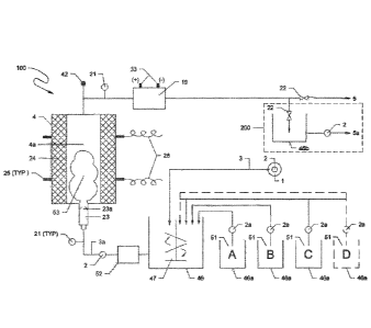
[0064] Figure 1 depicts a generalized basic version of a system 100 for
in-line water
treatment with some optional components shown. An off-line version 200 of the
system 100
allows for the production of an oxidizing fluid or disinfection solution when
using treated
water or a clean water source and an optional collection tank to store the
produced water.
Water or aqueous fluid 1 to be treated is transferred by pump 2 via conduit 3
into a mix tank
46 where a single reagent 51 is, or multiple reagents 51 (A, B, C, D. etc.)
are, fed by (a)
respective chemical feed pump(s) 2a into the mix tank 46 where the reagents 51
and feed
water 1 are blended using a rotating spindle or paddle mixer 47, or by other
means that are
also embodied in the disclosed process, including, for example, the sinusoidal
mixing reactor
as shown in Figure 2 replaces mix tank 46 and the hydrodynamic mixer 47.
-22-
CA 03133475 2021-09-13
WO 2020/205635 PCT/US2020/025482
[0065] Water and reagent mixture from tank 46 are fed by pump 2 through
contaminated water piping 3a into a cavitation "nozzle" comprising a shell 23
that houses
the nozzle's orifice tip 23a. An optional ozonator 52 is also shown in-line
prior to the intake
of pump 2. The nozzle typically decreases in cross-sectional area from the
point of fluid
entrance into the tip until it is at its smallest diameter at the nozzle tip
orifice where fluid then
enters an enlarged cross-section area of the discharge end of the shell 23.
The shell 23
may also be tapered from the outlet of the shell 23 back to point where fluid
enters the nozzle
23. A wide variety of designs and styles of nozzles may be suitable for use
with appropriate
engineering and trials that when utilized in accordance with this disclosure.
The overall
intent of this hydrodynamic cavitation nozzle 23/23a is to increase fluid flow
velocity and
pressure and then abruptly decrease the flow velocity and pressure when flow
enters the
enlarged area immediately downstream of the nozzle orifice. This, further
enhanced with
the pressure drop that occurs when fluid leaves the nozzle shell 23, causes
the rapid
formation and collapse of cavitation bubbles in the fluid as it enters into
the enlarged
cavitation chamber 4a of the cavitation reactor 4 and where cavitation bubbles
form a bubble
swarm 53 as discussed elsewhere in this disclosure specification. An
ultrasonic generator
(not shown) delivers electric power controlled for frequency, watts, and
amperage via the
power cables 26 to coaxial terminals 25 connected to the piezoelectric cell
transducers 24
where electric energy is converted to acoustic energy in accordance with the
ultrasonic
output frequency or frequencies of the transducers. The generator controls
output to the
transducers to increase or decrease power intensity and by modulating the
frequency of
power delivered to the transducers around their pre-set designs.
[0066] As shown in Figure 1, the cavitation reactor 4 creates both
hydrodynamic and
acoustic ultrasonic cavitation within the fluid being treated where both
cavitation forms are
created within the water of the cavitation reactor 4 in its cavitation chamber
4a and the
constituents including supplemental reagents carried by the water, and the
water itself,
cause the formation of oxidizing conditions and chemical oxidants as described
in greater
detail elsewhere in this disclosure to treat contaminants in water.
[0067] The cavitation reactor 4 comprises the hydrodynamic cavitation
nozzle 23/23a
and the cavitation chamber 4a where cavitation caused by the hydrodynamic
cavitation
-23-
CA 03133475 2021-09-13
WO 2020/205635 PCT/US2020/025482
nozzle 23/23a is enhanced from cavitation caused by the ultrasonic piezo-
electric cells 24
mounted to the sidewalls of the cavitation chamber 4a within which is the
bubble swarm 53.
The cavitation reactor 4 is preferably positioned vertically with feed water
introduced at the
bottom and water egress at the top of the reactor 4 where outlet piping can be
fitted with a
liquid/gas separation valve 42 if gas removal is needed, for example to remove
carbon
dioxide or other gases from contaminant destruction. Water is then directed
past a
monitoring/sensor and control point 21 into the electro-chemical oxidation
cell 19 where
water and its carried constituents including various oxidants, partially or
untreated
contaminants, and propagating cavitation bubbles from the cavitation reactor 4
are
subjected to the electrochemical oxidation conditions and reactions created by
the
electrolytic cell. A variety of commercially available ultrasonic reactors may
be viable for
use in the treatment system described herein, provided that hydrodynamic
cavitation is also
created within the cavitation reactor, and where a bubble swarm is created
that can pass
through and egress the reactor 4 such that water is in hydrodynamic and
acoustic energy
derived cavitation resonance and the bubble swarm can flow into an electro-
chemical reactor
19 that is electrically connected at terminals 33 to a power source (not
shown). In another
preferred embodiment, water from the reactor 4 can enter an in-line static
mixer such as the
sinusoidal mixing reactor 300 depicted in Figures 1A, 1B, and 1C in other
preferred
embodiments where oxidation reactions can both proceed and be enhanced in all
configurations and geometries prior to processing by the electrochemical
oxidation cell to
accommodate the various ranges of selectivity and rate of contaminants'
scavenging by the
various oxidants and mixtures thereof.
[0068] The system 100 as shown in Figure 1 has a direct discharge 5 from
the
electrochemical oxidation cell 19 and illustrates an in-line embodiment of the
process
equipment, and where another embodiment can be configured as a manufacturing
process
(incorporating system 200) for a strong oxidation fluid or disinfection
solution product 5a
produced by the process equipment. In this embodiment, feed water 1 can be
sourced from
treated or clean water so that the generated oxidant fluid may be retained in
a storage tank
46b prior to outlet 5a delivery for use at another time or location. When the
oxidizing fluid
manufacturing process configuration (incorporating system 200) is preferred as
well as with
configuration 100, reagent(s) 51A, B, C, D may be selected depending upon the
desired
-24-
CA 03133475 2021-09-13
WO 2020/205635 PCT/US2020/025482
qualities of the final end-product. As examples for the configuration
including system 200:
groundwater, rain, lake or stream, ocean, etc. water and industrial grade
supplemental
reagents may be desired for a general use; potable water and food grade
reagents for
another level of quality; and whereas, use of laboratory grade deionized water
and high
purity analytical grade reagents will provide for uses where impurities would
be not be
desired as in the pharmaceutical industry or other applications where trace
contaminants
would be problematic for final use applications for outlet 5a water.
[0069] Figure 1 also shows at least one location where an ozone generator
52 with
venturi injection can be positioned before pump 2 in-line 3a prior to
cavitation nozzle 23/23a.
In this location, the ozone outlet venturi injector of the generator 52 will
deliver ozone to the
lower pressure water prior to pump 2 that will increase water pressure in pipe
3a prior to the
cavitation tube 23/23a. It is well known that ozone gas bubbles will be
compressed when
under pressure, and the bubble volume, and thus surface area, will be
minimized with some
ozone advantageously driven into a more dissolved equilibrium state within the
water. This
will facilitate contact between the gas bubbles, ozone molecules in solution,
and
contaminants within the water, thus increasing the efficiency of constituent
reactions with
ozone and overall oxidation reactions within the apparatus.
[0070] For both the in-line system 100 and manufactured product
(incorporating
system 200) processes, a variety of process control sampling ports, monitoring
points,
sensors, meters, and other instruments' positions 21 may be provided within
and between
system components. Data and/or sensor signals obtained from these locations
may also be
used to engage or actuate valves 22, and/or pumps 2 and 2a that may also be
manually
operated in more basic applications of the process equipment.
[0071] Referring to Figure 1A, the example presented illustrates another
configuration
of an in-line treatment process of the system 100. Differing from Figure 1,
the supplemental
reagents 51 stored in tank 46 are added to the water being treated via a
chemical feed pump
or pumps 2a that deliver reagents to an in-line manifold 54. Figure 1A also
illustrates serial
alignment in singularity of various process components, but with a plurality
of serial device
sequences that include a sinusoidal mixing reactor 300 and an electro-chemical
cell reactor
19 with each singular device train positioned on either side of the cavitation
reactor 4.
-25-
CA 03133475 2021-09-13
WO 2020/205635 PCT/US2020/025482
Multiple process control and monitoring points 21 are depicted throughout the
system 100.
One benefit of this configuration and serial device alignment of a plurality
of components is
to provide additional oxidation conditions that may be needed to further
polish the water
being treated, and yet another important application would be where more
easily oxidized
substances or a high loading of substances are treated in the first series of
components and
the cavitation reactor, and then subsequent treatment is performed where
concentrations of
remaining substances, and/or oxidation by-products and intermediaries are then
treated
prior to discharge. While not shown, yet another embodiment would be the
addition of yet
a third, or more, serial system(s), with or without another cavitation reactor
4.
[0072] Figure 1B, like Figure 1A also includes an in-line delivery method
of
supplemental reagents. Unlike Figure 1A, however, Figure 1B includes a flow
divergence
where water splits into a parallel plurality of single system components
consisting of a
sinusoidal mixing reactor 300, an electrochemical oxidation cell 19 and a
cavitation nozzle
23/23a. Flow confluence from the nozzles is within the cavitation chamber 4a
of the
cavitation reactor 4. Another embodiment illustrated in Figure 1B is the
inclusion of an
optional or alternative transducer rod 24a (provided in addition to or
substituting for
transducers 24) that is inserted along the vertical centerline of the
cavitation reactor 4. The
rod 24a may be sized based on frequency, diameter, length, and material of
construction.
The positioning of the rod within the chamber may also be offset from the
centerline and
accompanied by additional rods to provide a plurality of rod transducers that
may be of the
same or different frequencies and geometric measurements. While Figure 1B
depicts four
(4) transducers 24 mounted to the sidewalls of the reactor chamber, and a
single transducer
rod 24a, the transducers 24 may be reduced in number and adjacent to or
opposing others
across the chamber, depending on performance of a single or plurality of rods
on any given
fluid and its constituents being treated if a rod or rods are provided.
[0073] Figure 1C presents yet another example of a singularity and
plurality of
equipment components. It illustrates an in-line processing with a singular
reagent manifold
54 for supplemental reagent delivery, and then fluid divergence into a
plurality of singular
process components serially aligned where components include a sinusoidal
mixing reactor
300, an electrochemical oxidation cell 19, a cavitation reactor 4, another
sinusoidal mixing
-26-
CA 03133475 2021-09-13
WO 2020/205635 PCT/US2020/025482
reactor 300, and yet another electrochemical oxidation cell 19 before fluid
converges prior
to its outlet 5. A benefit of this configuration, with the potential to
increase the plurality using
multiple serial alignments allows for increased retention, thus process time
within the system
without decreasing feed flow rate. Process redundancy from parallel systems
will also allow
for servicing any single serial alignment without requiring shut-down the
entire processing
system. Another benefit would be to utilize a singular parallel system for
treatment of a
single absorber in a treatment train (Figure Series-6). Still another benefit
would be to
achieve treatment objectives for the entire process where two or more
constituents are
problematic and require slightly different process variable settings and that
the blended end-
product meets all discharge or treatment objectives relative to overall
contaminant
concentrations and their respective destruction within each singular device
alignment.
Without diverging from the present invention, component sequencing order can
be adjusted
within series alignments of illustrated components between the plurality of
alignments such
that the combined outcomes of the re-sequenced, or differently sequenced
component
alignments produce a composite outcome of treated water that meets overall
treatment
objectives for the fluid being processed.
[0074] The components of the systems 100 and 200 depicted in Figures. 1,
1A, 1B
and 1C and optional devices also embodied in this disclosure that contact
water being
treated and various supplemental reagents should be made from materials that
are inert and
non-reactive to the severe cavitation and oxidizing conditions created within
equipment
components. Further, materials should not contribute or leach constituents
into the fluid as
a result of contact and direct exposure to the fluids and their
characteristics. Ideally, high
quality stainless steel is the preferred material, however, ceramics,
plastics, aluminum, steel,
etc. can be used for specific applications where less harsh operating
objectives are followed,
noting that any material that contacts fluids being treated will be exposed to
both corrosive
and erosive conditions within the cavitation and other reactors. Further, and
specifically for
cavitation components to be most efficient, the materials should not dampen or
absorb the
energy within the cavitation chambers that would compromise critical
cavitation bubble
formation and collapse. Electrochemical oxidation cell electrode components
are discussed
elsewhere in this specification, however with respect to cell housings that
hold electrodes
and/or contact the fluid, they should have similar properties to those
discussed above,
-27-
CA 03133475 2021-09-13
WO 2020/205635 PCT/US2020/025482
however, conductivity between component parts must be properly insulated and
grounded
to eliminate unwanted conductivity, short-circuiting, and certainly for
safety.
[0075] Sinusoidal Mixing Reactor
[0076] Figure 2 depicts an embodiment of an in-line flow-through
sinusoidal
serpentine pipe/tube mixing reactor 300 suitable for use in the system
described herein. The
mixing reactor as depicted shows various feature examples that can be
incorporated
optionally and singularly or in plurality into its design for functional
mixing of aqueous fluid
or water with reactants created by or delivered to the mixing reactor 300 and
received by or
released to the system described herein. Supplemental to blending water with
its
constituents, the unit 300 provides additional time for various reactions to
occur while
importantly providing for additional oxidation and other embodiments,
depending upon the
various optional devices incorporated into the design of the unit for any
given application.
The mixing reactor causes limited backpressure and hydraulic head loss while
also serving
as a passive flow-through mixing and reaction device for reactants in the
fluid. An in-line
component as that depicted, or one that provides the same functionality, may
be inserted at
any location between or after various process components of the water
treatment system to
maximize desired mixing and process reaction performance outcomes. As
illustrated in the
Figure 1-series, the mixing reactor 300 is positioned after supplemental
reagent addition to
water before it is processed by the electrochemical oxidation cell 19, and
also after the
cavitation reactor 4. In another embodiment that is not shown, the mixing
reactor may
alternatively be positioned after either or both of the electrochemical
oxidation cells. In either
configuration sequence, water in hydrodynamic and acoustic cavitation
resonance is
critically and preferably delivered through the mixing reactor to the
electrochemical oxidation
cell as embodied in the present invention.
[0077] When installed within the water treatment systems described
herein, the
sinusoidal serpentine mixing reactor 300 shown in Figure 2 provides for in-
line mixing and/or
reactions of a flowing fluid with and between its carried constituents,
including those that
may have been generated in a process system component upstream of the fluid
inlet 3,
and/or when supplied to the fluid in or prior to entering the mixing reactor.
It is well reported
and known that in-line mixing is accomplished by means of increasing contact
areas of
-28-
CA 03133475 2021-09-13
WO 2020/205635 PCT/US2020/025482
striated flow caused by differential velocity between layers of flow within
the fully flooded
pipe or tube. Unlike other serpentine mixing devices, the mixing reactor
described herein
includes: decreasing and increasing pipe/tube alignment curvature radii 45
(for example RI ,
R2, R3); constriction 43 and expansion 44 of pipe/tube cross-sectional area;
gas outlet(s)
42; optional in-line screen, catalyst retaining/ granular solid
extraction/reaction enhancing
devices 34 (e.g., also UV reactor 34a); a lack of flow obstacles such as
pipe/tube joints or
fittings, paddles, blades or other abrupt flow impactors and no motorized or
energy
consuming hydrodynamic devices so that fluid leaving the unit at the fluid
outlet 5 is mixed
adequately for subsequent treatment, processing or discharge with limited
pressure drop.
To further differentiate from a conventional serpentine mixing device, the
mixing reactor also
provides for the generation and delivery of oxidants via the ozone generator
and injection
feature 52 coupled with enhancing devices 34 (e.g., also UV reactor 34a) to
facilitate
contaminant and constituent alteration, i.e., the formation of new oxidants,
and the oxidative
destruction of the contaminant substances and compounds.
[0078] As shown in Figure 2, the tube includes curvilinear radii changes
45 spaced
along the overall plane of the unit within the pipe/tube run length of the
mixer. The unit may
be constructed from a variety of material choices such as stainless steel,
HDPE, PVC, etc.,
however, its longevity and resistance to degradation from the chemistry and
other
characteristics of the fluid being treated are necessary design criteria,
particularly with the
strength of the oxidants being created, as well as potential contamination
sourced from the
materials of construction that may contain PFAS bearing telomeres such as PFOS
and
PFOA among others in TFE or PTFE common in pipe fitting joint compounds.
[0079] In-line mixing performance is based upon flow velocity
differentials of fluid
flowing within a flooded pipe or tube and the low viscosity and low Reynolds
number of
aqueous fluids. The velocity of a flowing fluid in a closed channel or pipe is
greatest within
the core of the fluid's flow due to the lack of a friction surface created by
the pipe/tube wall.
However, in a radius of smooth-bent pipe/tubing 45, the water flow within the
pipe/tube
travels longer distances on the outside of the radius, and slower on the
inside of the radius.
This imparts differential velocity layers within the water volume present
within the length of
the tube bend(s). As flow approaches a pipe alignment curvature 45, it moves
towards the
-29-.
CA 03133475 2021-09-13
WO 2020/205635 PCT/US2020/025482
outer pipe/tube wall due to centrifugal force, thus creating velocity and
micro pressure
gradients yielding vortical flows, and thus mixing. Secondary flow growth due
to a change
in curvature (R-1, R-2, R-3) from a straight alignment to bent, back to
straight, and then bent
back in the other direction (sine wave pattern) causes transverse directional
fluid flow that
shifts flow vortices as flow encounters the curvatures 45 between the pipe
sidewalls and the
central core where less friction exists to slow velocity.
[0080] Further mixing will result from differential flow velocity within
a pipe run bend
by providing several varied changes in bend radius (R-1, R-2, and/or R-3) turn
sharpness.
As the curvature radius is reduced and the bend sharpens, fluid velocity
differential
increases within the pipe through the radius curvature run. As the curvature
radius
increases, velocity differentials decrease causing more changes in flow
patterns, thus
enhancing mixing.
[0081] Another blending feature of the disclosed mixing reactor is
provided by
constriction 43 and enlargement 44 of the pipe/tubing diameter using welded
bell or such
taper/flare fittings without inclusion of turbulence causing obstacles such as
paddles, blades,
or deflectors that create local strain to passing fluids and carried solids.
By changing the
pipe cross-sectional geometry of the pipe, fluid velocity also differentiates
as fluid passes
through the pipe diameter geometry transition. Under constant pressure and
flow, velocity
will increase as the diameter decreases, and will decrease as the diameter
decreases. As
with alignment curvature, cross-sectional area changes disrupt flow layers and
cause
transverse velocity patterns that increase the interaction and contact of
water with and
between its carried constituents.
[0082] Process control sensors and monitors 21 should be installed prior
to and/or
after serpentine pipe/tube bends to evaluate mixer performance, reaction
status, and/or
operating conditions at locations where such monitoring is desired. An
adequate distance
between the monitoring location and the nearest tube/pipe geometry change will
likely be
required based upon monitoring/sensor manufacturer recommendations. Typically,
a
distance of ten (10) times the radius is adequate. Gas/liquid separation and
gas removal
valves 42 may also be added where gas may collect at various locations along
the length of
the mixing tube 300, and/or depending upon the spatial orientation of device
when installed.
-30-
CA 03133475 2021-09-13
WO 2020/205635 PCT/US2020/025482
[0083] An in-line magnet/screen, catalyst retaining/ granular solid
extraction/reaction
enhancing capture/containment device 34 is intended to show the inclusion of a
device or
devices that can be located at any number of locations within this unit, or
other components
of the water treatment system. The devices of this unit 34 may include
material screens to
remove debris and large particles such as small media fines, to retain and
position granular
catalyst in-line with fluid flow to facilitate reactions, and/or include
external magnets that help
excite constituents, or align those that are polar charged constituents within
the fluids to
facilitate reaction, or to remove particles and fines that respond to magnetic
fields (such as
ZVI) that carries downstream from the media reactor chamber. For ZVI, particle
fines will
be magnetically held against the inner wall of the mixing reactor. The
installation for this
functional unit may be at the bottom of a curvature and include a cleanout
portal for
maintenance servicing, however ZVI particles, such retained, may provide
further benefit to
process reaction with their presence. The locations of the capture/containment
device 34
and other features herein described are depicted in this Figure 2 is intended
to show that
the functions such an installation provides is or are part of the described
embodiments, and
do not specify an exact location within this device, or to differentiate
between the functions
of the device 34 or others herein disclosed.
[0084] In another embodiment shown on Figure 2, the tube reactor includes
a
generator for ozone 52 where ozone is venturi injected into the fluid flow
prior to velocity and
pressure increases caused by the tube diameter constriction 43. As a gas with
a strong
oxidation potential, ozone can be limited in its ability to oxidize various
contaminants due to
the water-gas interface at the surface of the ozone bubbles and their
respective surface
areas. When pressure is increased on the fluid at the tube constriction 43,
gas bubbles will
decrease in size, thus decreasing their surface area and have a greater
ability to react with
target organic constituents that are dissolved in the water. Further, with
adequate pressure,
ozone may also enter a preferable dissolved state where liquid-liquid
interaction at the
molecular level with contaminants is facilitated and oxidation reactions are
more efficient.
[0085] Figure 2A shows an embodiment where the enhancing device 34 is
specifically
an in-line ultraviolet (UV) light reactor installed in the tube reactor 300
downstream from the
ozone injection 52 and the tube expansion 44 where the flow velocity will
decrease. In in
-31-
CA 03133475 2021-09-13
WO 2020/205635 PCT/US2020/025482
the presence of UV light, ozone will form powerful hydroxyl radicals with
elevated oxidation
potential that will attack oxidizable contaminants. With a decrease in flow
velocity, contact
time between hydroxyl radicals and contaminants will increase. Wavelengths of
UV lamps
58 can be varied and optimized to achieve suitable oxidation of various
compounds, or to
provide for disinfection sterilization of biological species. Catalysts can
accelerate chemical
reactions without contributing reactants to the overall reaction. The UV
reactor 34a detail
as depicted in Figure 2 includes a media screen 34h that can be used to retain
catalyst in
the fluid flow and within the influence of UV light. The UV reactor 34a as
shown is a bolt-in
device comprised of a high quality optical quartz glass tube 56 that is flared
to a flange at
both ends and fitted in-line with the tube of the reactor 300 between two
mixing tube flanges
59, secured with a chemically resistant gasket and flange-to-flange bolt-kit
59. The detail
shows by example an embodiment where UV lamps 58 are positioned within a
protective
UV lamp housing 57 and outside of the optical glass 56. Other designs and
commercially
available devices for UV irradiation of water in a pipe 55 are also suitable
for inclusion in the
sinusoidal mixing reactor 300.
[0086] Yet another benefit of the mixing reactor embodiment is to allow
reactants,
either added to the fluid or created by the treatment components of the
invention, and their
reactions to proceed due to mixing and reactant contact within the sinusoidal
unit 300.
Mixing will be more laminar than that of other turbulent static/hydrodynamic
mixers, thus
minimizing backpressure through the unit.
[0087] Another embodiment of the mixing reactor not shown in Figure 2 is
a change
in length of pipe/tube runs (legs) between curvatures. Leg lengths can be all
the same
dimension, or leg length may be varied throughout the device to further
facilitate mixing and
reactions. Also not depicted in Figure 2 is the positioning or orientation of
the mixing reactor
300. It may be placed so that serpentine pipe plane is flat and parallel to
the ground, or the
plane rotated with the inlet 3 at the bottom and the outlet 5 at the top.
These orientations
may either facilitate performance and/or accommodate the space available for
its location
within a system at the site of the system's application. The UV reactor may be
installed
vertically or horizontally within the mixing reactor 300, or operated in an up
or downflow
-32-.
CA 03133475 2021-09-13
WO 2020/205635 PCT/US2020/025482
position. A gas/liquid separation portal and valve may be appropriately
provided and located
when needed to remove any generated or accumulated gas.
[0088] The mixing reactor described herein provides a high mixing index,
increases
residence mixing/contact/reaction time with an increase in overall length and
the quantity
and frequency of features herein described, provides low resistance to flow
thus reduced
head loss with lower pump energy demand without need of a motor driven or
passive flow
blocking obstacles such as ribbons, spindles, paddle or flow diversion arrays,
and also
contribute to the oxidant formation and subsequent oxidation reactions.
Importantly, the
design of the mixing reactor allows for the passage of water in cavitation for
electrochemical
oxidation cell 19 processing if the cell is positioned downstream of the
mixing reactor 300.
[0089] A plurality of sinusoidal mixing reactors can be arranged in
parallel with
individual units connected to a flow splitting control manifold positioned
prior to the inlet 3
and after the outlet 5 of each unit, or in subsequent serial configuration.
These configuration
arrangements can accommodate situations where flow rate from the water source
fluctuates
or is intermittent, or if more or less mixing and retention time is needed to
facilitate desired
results. Other Figures of this specification present other options for the
insertion location of
the tube mixer 300 into the system.
[0090] Cavitation Reactor
[0091] Figure 3 depicts a single cavitation nozzle 23/23a with its shell
tube 23 and a
nozzle tip fitted tip 23a flow-through fluid dynamic acoustic cavitation
reactor 4 where
hydrodynamic and acoustic cavitation of water being treated is created within
the same
cavitation chamber 4a. Fluid from a source 1 that may include raw system feed
water, or
water from another component, e.g., a sinusoidal mixing reactor 300 in Figure
2, or an
electrochemical oxidation cell 19 in Figure 1-series is fed by a high pressure
pump 2 via a
pipe inlet 3 to the hydrodynamic cavitation nozzle's 23/23a tube shell 23
where the flow is
greatly restricted and fluid velocity and pressure are increased by the
cavitation nozzle shell
23 and tip 23a. Immediately upon passing through the orifice of the nozzle tip
23a, the flow
enters the enlarged cross-sectional area of the tube shell 23 egress and the
further enlarged
area of the cavitation chamber 4a within the cavitation reactor 4. Because of
the differential
drops in fluid pressure (>25 psi for the reactor 4 shown) and velocity
immediately upon
-33-.
CA 03133475 2021-09-13
WO 2020/205635 PCT/US2020/025482
departure from the nozzle tip 23a, cavitation bubbles are created and combine
to form a
bubble swarm 53 (shown in FIG. 1). Within the cavitation chamber 4a, the
hydrodynamically
cavitated water is also subjected concomitantly to ultrasonic acoustic
cavitation effects from
the piezoelectric cell arrays 24 of the reactor 4. Ultrasonic energy is
created by the
ultrasound power generator 27 delivered by power cables 26 connected by
terminals 25 to
the piezoelectric cell arrays 24 where electric energy is converted to high
energy acoustic
energy at frequencies ranging from 10kHz to over 500 kHz, but where typical
frequencies
are at 25, 40, 68, and/or 176 kHz, or in combinations, thereof, respectively.
Frequencies of
25, 40, and 68 kHz are well suited for the purposes of this technology,
although lower or
higher frequencies may be required for specific contaminants in various
complex aqueous
waste streams that can be selected through optimization treatability studies
using the
apparatus and various configurations disclosed and embodied herein.
[0092] Of particular importance to some embodiments of the technology
described
herein as discussed elsewhere in this disclosure, is the oxidation potential
latency and
cavitation bubbles that carry from the reactor 4 via the fluid outlet 5 to and
through a
sinusoidal mixing reactor 300 where oxidation reactions are continued and
enhanced to
achieve desired contaminant destruction immediately within the follow-on
device. In a
preferred embodiment, an electrochemical oxidation cell 19 shown in Figures 1-
series, for
example, immediately receives the actively cavitating fluid flow with bubble
swarms 53 from
the outlet 5 for enhanced oxidation of contaminants and intermediary by-
products by
oxidants created in the reactor 4 and the cell 19 of Figure 4 from the
operating conditions
and supplemental reagents that form ionic radicals with elevated oxidation
potentials, See
Table 1 elsewhere in this specification.
[0093] A liquid/gas separation portal 42 may be provided to remove gases
from the
reactor 4 that form during oxidation reactions. As shown in the figures,
vertical positioning
is desirable with an up-flow operation to prevent the accumulation of air and
gas within the
cavitation reactor device 4, although horizontal operation can also be
effective.
[0094] The untreated water inlet 3 and treated water outlet 5 may be
fitted with various
instruments and devices 21 for monitoring and controlling the device while in
operation,
and/or for sampling water for other testing and analyses. Process control
sensors and
-34..
CA 03133475 2021-09-13
WO 2020/205635 PCT/US2020/025482
monitoring devices 21 will allow for data gathering for process operation
variable
determinations and/or conversion to programmable signals to control flow, pump
rates/pressure, valves, electric current and ultrasonic energy generation and
other process
control adjustments.
[0095] Figure 3A shows another embodiment where a dual collider nozzle
assembly
23b replaces a single cavitation nozzle 23/23a. In the collider assembly 23b,
single nozzles
23/23a attached to feed fluid piping 55 are aimed to directly oppose each
other when
mounted in a "T" or yoke 60 where within jet streams from the nozzle 23/23b
collide in
chamber 4c that releases actively cavitating water and a bubble swarm 53 into
the cavitation
chamber 4a of the cavitation reactor 4. Bubble swarms from each nozzle 23/23a
collide
directly head-on in the chamber 55 of yoke 60 to impart more energy between
the directly
opposing cavitation bubble swarms and dynamic fluid flow. To further optimize
effects of
the dual nozzle collider device 23b, operating feed pressures and flow
velocities of each
nozzle 23/23a can be altered from each other, and different tip 23a diameters
can be
selected to further alter cavitation bubble and bubble swarm characteristics
to achieve
desired treatment objectives. In another embodiment of the hydrodynamic
cavitation nozzle
collider device 23b, the distance between each opposing nozzle 23/23a can be
changed by
elongating or shortening the length of the yoke 60. Other changes in nozzle
geometries
including shell and yoke diameter, nozzle tip orifice diameters and shapes
that are also
embodied can be designed to produce specific or custom outcomes with respect
to
hydrodynamic cavitation within the reactor chamber 4a when also combined with
sonication
sourced from the acoustic energy transducers and piezoelectric cells.
[0096] Electrochemical Oxidation Cell
[0097] Figure 4 depicts an electro-chemical oxidation cell 19 that
induces oxidation
reactions as a component of the present technology. Fluid feed via inlet 3
(sourced from
other components of the system, for example a cavitation reactor 4 shown on
Figure 1, or a
sinusoidal mixing reactor 300 shown on Figure 2) enters cell 19 as may be
controlled by a
manual or automated valve 22 and that can be adjusted based on data derived or
otherwise
obtained from monitoring and control sensors/instruments/sample tap components
21
installed at the fluid inlet 3 and/or in combinations of data and trigger
points obtained from
-35.
CA 03133475 2021-09-13
WO 2020/205635 PCT/US2020/025482
sensor/monitoring components 21 at the fluid outlet 5 from the cell 19. Fluid
outlet 5 may
also be controlled by a manual or automated valve (not shown in FIG. 4). Upon
entry to the
cell 19, fluid flows into the electrode gap 28/29 created preferably by
dimensionally stable
electrodes, e.g., an anode 28 and a cathode 29 set in parallel to each other
and separated
by 1-12 mm. Electrodes 28 and 29 are connected at terminals 33 under a
terminal cover 32
by wiring (not shown) to a DC power source (not shown) that controls current
voltage and
amperage to deliver the desired current density for the electrode surface area
of the provided
device and to achieve oxidation conditions optimized with the other system
components to
achieve desired water treatment outcomes. By supplying power with polarity
reversal
capability, electrode cleaning may be accomplished as part of an operational
operation and
maintenance plan.
[0098] Preferably, the electrode materials are dimensionally stable, not
sacrificial, and
made from boron-doped diamond (BDD), tungsten, stainless steel, graphite,
graphene,
tungsten, or other suitable reactive-surfaced conductive non-deleterious
material that will
cause the necessary electrochemical oxidation reactions with the water and its
constituents
to benefit treatment or be treated at appropriate current densities and power
wattage. In a
preferred embodiment, the anode 28 and cathode 29 is boron-doped diamond on a
niobium
substrate, and the anode 28 electrode is tungsten where the boron-doped
diamond
electrode provides a wide electric potential range. As an electrode pair, the
anode 28 and
cathode 29 create an electrode gap 28/29.
[0099] The electrodes 28 and 29 are sandwiched or secured within a tight,
close
tolerance housing 39 and are seated with an appropriate leak preventing gasket
or seal 31
and structurally backed against a supportive, non-conductive insulating
barrier 41 for a
single sided BDD electrode. Together, electrodes form a pair and create the
electrode gap
28/29 ranging from 1 or 2mm to 12 mm, depending upon characteristics of the
fluid being
treated (including fluid conductivity), and performance response to reactions
facilitated by
the cell 19. The housing 39 may be modified to more closely resemble those in
Figures 5A-
5C when using double sided electrodes, a stack or bundle of paired electrodes,
or a plurality
of electrodes are desired with dual-sided reactive surfaces.
-36-.
CA 03133475 2021-09-13
WO 2020/205635 PCT/US2020/025482
[0100] Fluid egresses the electrode gap and the cell via the fluid outlet
5, passing
another array of sensors and monitoring devices 21 and an optional gas/liquid
separation
portal 42 to remove gas that may be generated by the cell and reactions within
the fluid. A
control valve (not shown) may be used to control flow as needed. Fluid that
exits from the
cell outlet 5 may be directed to other components, such as the sinusoidal
mixing reactor 300
shown on Figure 2, or a storage tank 46b of Figure 1, or other invention
components shown
in other Figures. Another preferred embodiment is the positioning of the
electrochemical
oxidation cell 19 so that it directly discharges into a cavitation reactor 4,
however, the
electrochemical oxidation cell 19 must be able to withstand operational water
pressure
required to cause the pressure differential across the cavitation nozzle or
nozzles.
[0101] A single cell 19 or a plurality cells in parallel or serial
configuration can be
provided in the water treatment system described herein to process flow rates
and/or
aqueous fluid constituents of any given application. An electrolytic oxidation
cell or cells can
be combined in parallel to each other and in series before or after a single
or plurality of
cavitation reactors to generate or enhance the generation of hydroxyl and
other oxidant
radicals that react with fluid-contained constituents to affect their
oxidation (loss of electrons)
and subsequent organic substance destruction. Some examples of a single cell
19 in a
plurality of cells are shown in Figures 1B and 1C. As such, the cell 19 or
cells may be
installed within the water treatment system prior to, between, or after other
components of
the disclosed system to better optimize overall performance, equipment and
operating costs,
and the overall efficacy in achieving desires treatment objectives.
[0102] Large Cav/ECO Reactor
[0103] Figures 5A, 5B, and 5C illustrate various configurations of the
fluid dynamic
and acoustic cavitation (Cav), and electrochemical oxidation (ECO) cell
components
combined in a larger integrated Cav/ECO reactor 4 that includes a cavitation
chamber 4a
and an electrochemical oxidation chamber 4b suitable for use in the systems
described
herein. The figures show: fluid feed inlets; hydrodynamic cavitation
nozzle(s); ultrasonic
acoustic energy piezoelectric cell transducers; electrode pairs and bundling
configurations;
ultrasound and EC power supply; optional cavitation target plates; a reaction
equalization
chamber and fluid outlets, all of which integrate to enhance performance as a
combined unit.
-37..
CA 03133475 2021-09-13
WO 2020/205635 PCT/US2020/025482
Not shown but still embodied as a part of the integrated system is an optional
sinusoidal
mixing reactor 300 of Figure 2 that can be placed before and/or after the
Cav/ECO reactor
4 in embodied in Figure 5-series. The type of unit presented in these figures
represent a
basic embodiment of the disclosed system. Other styles, geometries, and/or
configurations
of the units represented in these figures are also possible in systems when
inertial and non-
inertial cavitation and electrochemical oxidation are provided to
concomitantly benefit or
derive benefit from other components of the system and process water in a
combined reactor
unit and overall treatment system 100 (or 200).
[0104] The untreated water inlet 3 and treated water outlet 5 may be
fitted with various
instruments and devices 21 for monitoring and controlling the device while in
operation,
and/or for sampling water for other testing and analyses. Other components not
shown but
which may be provided in the feed line 3 or the discharge line 5, and include
magnets,
screening baskets, and/or retaining or extraction/filtering devices (not
shown) as discussed
elsewhere in this specification, as well as a sinusoidal mixing reactor such
as the one
illustrated in Figure 2.
[0105] Figures 5A, 5B, and 5C depict multiple views of a flow-through
multi-chamber
tank-like containment reactor 4 where both a cavitation reaction chamber 4a
and an
electrochemical oxidation reaction chamber 4b are provided in a single
component 4 to
increase treatment flow capacity of the system described herein, while also
being able to
process more complex aqueous fluids characterized by more constituents and/or
of higher
concentration. As shown in this Figure-series, a difference in depicted
configurations is the
direction at which fluid is delivered through the hydrodynamic cavitation
nozzles 23/23a,
whether horizontal or vertical. Other differences and variations are also
possible and
embodied within the Cav/ECO reactor 4 described herein. While Cav/ECO reactor
4 unit is
illustrated in singularity, it may be provided as a plurality of reactors 4 in
parallel or serial to
each other.
[0106] The geometry of the unit shown in Figures 5A, 5B, and 5C is
intended to allow
for the processing of increased water flow, increased retention time, and/or
impart expanded
influences of cavitation and/or electro-chemical oxidation for more complex
and/or
recalcitrant fluids and their constituents. The anode 28 and cathode 29
electrode pairs 28/29
-38-
CA 03133475 2021-09-13
WO 2020/205635 PCT/US2020/025482
in the illustrated examples can be horizontally stacked in bundles where
opposing sides of
an adjacent specific electrode pair create another functional electrode gap
for process
reactions. Figure 5C provides an end view of the reactor 4 in which a
plurality of cavitation
nozzles 23/23a are aligned horizontally, although other alignment patterns,
such as vertical
as shown, may be alternately or dually combined and provided to expand the
resultant
cavitation field dimensions within the chamber 4a. Water levels are also shown
above which
electrodes 28 and 29 of a bundle are respectively connected at alternative
tabs by terminals
and wiring 33 on Figure 5C to the power supply (not shown). Detail A of Figure
5A shows a
non-conductive spacer bracket 41 with appropriate insulated channels 31 to
secure each
electrode and to minimize movement and prevent direct contact with other
electrodes.
Channel brackets 41 are fixed to the vertical side wall of the housing 39 in
alignment such
that individual electrode plates may be slid down each of their respective
channels so
singular electrodes may be readily serviced. As part of the overall housing
39, a locking
protective safety cover 30 is provided.
[0107] As shown in Figure 5C, water flows upward around individual
electrodes
through electrode pair surfaces of the electrode gap 28/29 (described
elsewhere in this
specification). As active water and the bubble swarm generated in chamber 4a
enters
chamber 4b, water is subjected to the additional oxidation effects and impacts
caused by
the electrochemical oxidation electrodes. Further the water in chamber 4b, its
constituents,
and electrodes are also irradiated with acoustic sonication energy provided by
additional
transducers 24 mounted to the housing 39 of chamber 4b with terminals 25
connected by
cables 26 to the power generator 27 (shown in FIG. 5A). In reaction chamber 4b
that
receives cavitated fluid from the lower reaction chamber 4a, water is also
subjected to both
cavitation and electrochemical oxidation, as well as the cavitation bubble
swarm that
originates in chamber 4a and propagates into chamber 4b. While these Figures
prospectively depict two chambers 4a and 4b, use of chamber 4b without
acoustic cavitation
in chamber 4a is also an embodiment where the combined oxidation effects of
hydrodynamic
and acoustic cavitation, electrochemical oxidation, and chemical oxidation
from oxidants and
oxidizing radicals are formed and conditions are created within the depicted
Cav/ECO
reactor 4 to destroy oxidizable materials, substances, and compounds carried
by water to
be treated.
-39..
CA 03133475 2021-09-13
WO 2020/205635 PCT/US2020/025482
[0108] At the top of the electrodes 28 and 29 within the housing 39,
water flows across
the overflow weir 39a as shown in Figures 5A and 5B and creates a nappe 39b as
it falls
into the reaction and flow equalization chamber 37. Water from this
compartment departs
the unit through the outlet 5 and appropriate control and monitoring 21 for
the process. A
pump (not shown) may be provided to facilitate fluid transfer and conveyance
should gravity
drainage not be acceptable or adequate for subsequent fluid handling.
[0109] It is noted that all forms of cavitation can be deleterious to
various materials
via erosive and corrosive effects. As such, spatial geometric placement of
cavitation
nozzles, their shell and tip designs, cavitation chamber design, and fluid
flow rate and
pressure may require optimization to minimize excessively harsh delivery of
bubble swarm
to chamber 4b where the electrodes are positioned to maximize their longevity.
Similarly,
the acoustic transducer 24 spatial positioning, frequencies, and level(s) of
applied power
should similarly be optimized in chamber 4b in conjunction with methods to
generated
cavitation that originate in chamber 4a. An option to protect electrodes,
primarily along their
edges, can include an armoring channel or protective frame. Yet another option
to minimize
deleterious effects to the electrodes would be minimize their exposure to
intense bubble
swarm by shortening the length of the overall electrode bundle geometry as
well as adjusting
their width along with the geometry of the reactor 4 and its housing 39 so as
to maintain or
provide adequate electrode surface area to achieve the desired output yet
distancing them
from the intense portion of a bubble swarm.
[0110] In the depicted larger Cav/ECO reactor embodiment of the present
invention,
Figure 5A provides a top view of a suitable reactor 4 where both cavitation
and
electrochemical oxidation are applied to water and its constituents. Water
from the source
1 or an upstream component of the system is pumped via pump 2 or delivered
into the feed
inlet 3 piping manifold that directs flow (control valves and monitoring
devices not shown) to
the horizontally aligned plurality of single cavitation nozzles 23/23a affixed
to the lower end
of cavitation chamber 4a. All or some of these single units may be replaced by
cavitation
collider assemblies 23b depicted on Figure 4B. In another embodiment, the
nozzles 23/23a
may be installed in the bottom of the chamber 4a for up-flow into chamber 4a
during
operation of the reactor 4.
-40.
CA 03133475 2021-09-13
WO 2020/205635 PCT/US2020/025482
[0111] With respect to Figures 5A, 5B, and 5C, aqueous fluid to be
processed is
delivered from the source 1 by a pump 2 or another system component via inlet
piping 3
through one or more of the cavitation nozzles 23/23a into the cavitation
chamber 4a.
Depending upon cavitation nozzles' 23/23a design, positioning (horizontal or
vertical), aim,
operating variables, and desired performance criteria of the reactor 4,
optional cavitation
target plates 35/35a (FIG. 5B) may be appropriately mounted in the chamber 4a.
For an
end-mounted horizontal nozzle 23/23a, or collider 23b on Figure 3A, target
plates 35 may
be desired, and for the vertical upward CavNoz 23a positioning, target plates
35a can be
used with positioning to accommodate the upper transducers 24. Ultrasonic
transducer
arrays 24 mounted with power terminals 25 connected to a power supply (not
shown) are
provided above the chamber 4a to irradiate water within. An added benefit of
the target
plate 35 positioning is allowing for targeting of both cavitation sources. A
target plate 35 can
be mounted on the flat and sloped floor section of the unit housing 39 that
inclines to the
combined ECO chamber 4b. In this arrangement, target plate 35 is impacted by
horizontal
nozzle 23/23a, but also serves to deflect cavitation bubble swarm up to the
[CO chamber
4.
[0112] Target plate material can be selected to provide acoustic energy
dampening,
deflection, or cavitation erosion of small plate material particles or
nanoparticles that become
reactants or otherwise participants in the reactions to treat various
compounds and
substances. Examples of suitable target plate materials are graphite,
ceramics, and/or metal
such as iron, aluminum, or copper, for example, however these specific
materials are not
identified to limit the field of invention with respect to target material
selection. Suitable
materials for target use are not limited to those indicated within the present
disclosure and
may vary where different materials may provide differing contributions and
benefits to the
desired reactions. One example of a target plate material is iron where small
iron particles
(ZVI - zero valent iron: Fe ) generated by cavitation erosion may provide
adequate iron
dosing where ZVI will lose electrons within reactions of the present
technology to form
ferrous iron (Fe+2), and where ferrous iron will form ferric iron (Fe+3) with
lost electrons being
available to remove chlorate, borate, nitrate, or other axo-ions from water by
reduction,
should one or more of these ionic species be an undesirable oxidation reaction
end-product.
-41-
CA 03133475 2021-09-13
WO 2020/205635 PCT/US2020/025482
Other benefits of ZVI and ferrous iron with respect to oxidation reactions are
discussed
elsewhere in this disclosure.
[0113] Granular Activated Carbon (CAC) Treatment
[0114] While activated carbon media is a preferred embodiment in this
component of
the technology as depicted in Figure 6-series, other media types may also be
suitable for
treatment in the disclosed equipment.
[0115] Figures 6A-1 and 6A-2 depict two operational modes of a single
granular
activated carbon cell as an integral component of the present technology.
Figure 6A-1
depicts a carbon cell in-service and on-line treating water from a
contaminated source.
Figure 6A-2 depicts the same carbon cell that is out-of-service and in-
treatment for
contaminants contained by the spent activated carbon within the cell. Figure
6B presents
an example where the equipment is depicted treating one (1) of three (3)
activated carbon
cells used to treat contaminated source water by removal of contaminants using
media
transfer from water to the carbon media, and where any one of the three carbon
cells may
be treated while either of the other two carbon cells remain on-line treating
the water.
[0116] Considering both Figures 6A-1 and 6A-2, treatment system 100 and
adjacent
carbon absorbers 49 and 50, and the contaminated water source are all fluidly
connected
with valves and manifold piping to comprise embodiment 400 where source water
3 is
treated by the carbon 15 in the absorber 49, and when spent, the carbon 15a in
absorber
50 of FIG. 6A-2 can be treated with system 100. In this embodiment system 400,
the carbon
cell 49 can be placed in-line for water treatment in 6A-1, or taken off-line
from the water
source 1 so that the same cell 50 in Figure 6A-2 can be placed into an in-
treatment operation
mode by the treatment system 100. As depicted in both Figures, the use of the
treatment
equipment in system 400 is embodied where the treatment system 100 combines
with the
carbon cell 49 to form an expanded system 400 and the carbon cell that was in-
service 49
in 6A-1 becomes a treatment reactor vessel 50 in 6A-2 for contaminated media
15a in 6A-2
treated by fluid from the treatment system 100 outlet 5a.
[0117] Figure 6A-1 illustrates a contaminated fluid or water source 1
that is transferred
by a pump 2 through feed piping 3 into the top of carbon cell 49 that is in-
service and on-
-42-
CA 03133475 2021-09-13
WO 2020/205635 PCT/US2020/025482
line to treat water and contains a granular activated carbon media 15 suitable
for removing
contaminants from the water. The carbon or other media 15 is retained within
the absorber
cell 49 by means of screened laterals 48. During water treatment, conventional
operation is
by downflow and the bottom lateral screens 48 retain the carbon media 15
within the
absorber cell 49. Water passes through the column bed of carbon media 15 and
exits
through the lower screens 48 and flows out of the absorber cell 49 to a piping
outlet 5 for
discharge or subsequent processing.
[0118] Figure 6A-2 illustrates the same configuration as shown in Figure
6A-1,
however, the carbon cell 49 now is removed from in-line service and placed in
an in-
treatment operation mode. Figure 6A-2 illustrates the in-treatment mode where
carbon cell
50 is no longer in-service or on-line treating water. Valves 22 are changed so
that oxidation
fluid from the treatment system 100 is transferred by pump 2a into the bottom
of the carbon
cell 50, through the lower lateral screens 48, up through the column bed of
spent carbon
media 15a that is retained by the upper lateral screens 48, and the water is
returned through
piping 5a back to the treatment system 100. In this operational mode,
recirculating oxidation
fluids between carbon cell 50 and treatment system 100 will not typically
require discharge
as the fluid will be re-usable, however, a storage tank (not shown) may be
part of the system
100 for surplus storage and re-use. During periods where carbon cell 50 is not
being treated,
the fluid in such a storage tank may be processed without passing through the
carbon cell
after it is treated until the fluid meets discharge requirements, or it can be
stored and reused
for treatment of the next carbon cell that is taken out of service and off-
line.
[0119] Again, referring to Figure 6A-2, as fluid 5a is pumped via pump 2a
up through
the spent carbon media 15a in cell 50, the oxidants in the fluid attack the
contaminants and
organic constituents adsorbed in the media. In addition, the spent media 15a
may also be
desorbed by fluid 5a and the released/removed constituents will be carried
back to the
system 100 in fluid 3a for subsequent treatment and processing. The flow rate
of fluid 5a
up through the absorber 50 and media 15a and back to the oxidation system may
equal that
of the process operation of the carbon cell 49 during water treatment, however
a preferred
flow is in the range of 2-20% of the in-service, on-line flow rate. It is also
noted that when
on-line treating water, carbon cell 49 of Figure 6A-1 may require periodic
backflushing to
-43,.
CA 03133475 2021-09-13
WO 2020/205635 PCT/US2020/025482
suspend the carbon bed 15 and facilitate the release and flushing of various
solids and
residue that may accumulate during water treatment processing production. In
such cases,
the piping may need to be modified to accommodate this backflush fluid,
operating pressure,
and solids loading, however, such modification may not be needed depending
upon the
specific condition and characteristics of a given water source 1 being
treated. When solids
are present in the source water 1, it is common practice to install other well-
proven water
treatment system components, such as settling, clarification and/or
filtration, that would
remove solids and other fines prior to the use of activated carbon polishing
of higher quality
water characterized by low solids loading, but that still contains oxidizable
substances and
compounds
[0120] Process control sensors and monitors 21 should be installed at the
feed inlet
and outlets of all components of the system 400 to evaluate performance,
reaction status,
operating conditions, and integrate with general system controls to affect
process operating
variables and auto-mated controls whether they be pumps, power controllers,
and/or the like
at locations where such monitoring is desired. An adequate distance between
the
monitoring location and the nearest tube/pipe geometry change will likely be
required based
upon monitoring/sensor manufacturer recommendations. Typically, a distance of
ten (10)
times the radius is adequate. Gas/liquid separation and gas removal valves
(not shown)
may also be added where gas may collect at various locations in the top of the
carbon cell
49/50 and at various other locations where it can accumulate within the system
400. In
another embodiment, non-contact tubing coils or heat exchangers can be
installed (not
shown) within the media bed chamber of the carbon cells 49 and 50 should
temperature
control benefit treatment.
[0121] While Figures 6A-1 and 6A-2 illustrations apply to an arrangement
of a singular
carbon cell 49 and 50 in one preferred embodiment 400, treatment component 100
and
carbon cells 49 and 50 can be provided in plurality such that carbon cells 49
are in parallel
or in series to each other, and carbon cell 50 can be taken off-line for
treatment while the
remaining cells 49 remain in service as illustrated in Figure 6B. Likewise,
the oxidation
treatment system 100 is also shown in singularity, but it may also be provided
in fluid plurality
-44-
CA 03133475 2021-09-13
WO 2020/205635 PCT/US2020/025482
should media 15a in multiple cells 50 require concomitant treatment for a
larger compound-
complex carbon system be required.
[0122] Figure 6B illustrates a serial plurality of in-service and online
carbon cells 49
and a single in-treatment carbon cell 50. With reference to Figure 6A-1 and
Figure 6B,
carbon cells 49 in FIG. 6B are plumbed in serial plurality with carbon cell
50, however as
shown, cells 49 are in-service and on-line treating water 3 through carbon
absorbers 49 in
a lead-lag configuration with and effluent discharge 5. Cell 50 is off-line
and being treated
for contaminants without interrupting the water treatment service provide by
cells. Treated
and oxidation fluid water 5a from the treatment system 100 is pumped 2a up
through carbon
cell #3 50 and the outlet water 5b is pumped 2a back into the treatment system
100 in a
recirculation mode. Once cell 50 has finished its in-treatment operation, it
can be put on
standby until the lead cell 49 is fully exhausted and spent with contaminants
from the source
water 1. Cell may then be placed in service as cell 49 in the lag position
behind cell 49
which will move to the lead position. Spent cell will be taken off-line and
out of service and
placed in the position formerly held by cell 50 so that its carbon may be
treated. With
appropriate piping of the system 400, valves 22, and pipe manifolds (not all
shown/numbered), the changes in service of the carbon absorber within the
overall system
400 can be made without interrupting the treatment of source water 1. It is
noted that not all
piping, valves, and manifolds are shown in Figure 6B, and those that are shown
are only
included to suggest certain aspects of that piping. Also not shown is that all
carbon cells 49
and 50 should be of equivalent design with respect to carbon media lateral
screens 48,
materials of construction, operating controls, valves 22, piping, and process
monitoring
devices and instruments 21 as may be required to facilitate efficient and
effective treatment.
However, if carbon cells are not equivalent, the treatment system 100 may be
operated
flexibly to accommodate each absorber's uniqueness whether by changing flow
rates, flow
pressure, power settings, and/or supplemental reagent dosing provided in the
treatment
system 100.
[0123] Concentrates and Brines
[0124] Figure 7 depicts the system 500 when applied to fluids where
contaminants
are present in concentrated levels. Examples of such fluids 5b include reject
from reverse
-45..
CA 03133475 2021-09-13
WO 2020/205635 PCT/US2020/025482
osmosis (as shown) and other such membrane-based separation technologies,
fluids
derived from the desorption of carbon, brines and well field fluids such as
might be generated
from various extraction processes, or resin and other media regeneration
processes, and
the like. Aqueous Film-Forming Foam (AFFF) with suitable dilution is also be
treatable with
the present technology.
[0125] By means of example and in this preferred embodiment 500, the
basic system
of the technology 100 and the manufacture of a powerful oxidizing fluid 200
(See Figure 1),
are both applied to treat oxidizable contaminants concentrated in reverse
osmosis
membrane reject concentrate 5b as shown in Figure 7 as one example. Influent
fluid 1 is
fed by pump 2 into a reverse osmosis system 80 where membrane separation of
contaminants generates a clean membrane permeate for discharge 5, and a
contaminant
concentrated membrane reject fluid 5b. As depicted, reject 5b is discharged
into a storage
tank 46 where it collects and the fluid 3a is transferred by pump 2 as volumes
reach a pre-
determined level in the tank to another storage tank 46a or through inlet
piping 3a to the
treatment equipment 100. Another pump 2 may feed fluid 3a from tank 46a into
the
treatment system 100/200 for processing. Treated or partially treated water
can be
discharged from outlet 5c and/or 5d into either tank 46 or 46a in one of two
(2) recirculating
treatment loops. Fully treated fluid can be discharged from outlet 5 as
treated effluent or to
another treatment component 82 of a master system of which this embodiment 500
is a
portion thereof, or where another treatment component 82 is a component of the
present
system 500. In another configuration of the embodiment (not depicted),
concentrate fluid
5b to be treated can be directly fed to the treatment system 100 without being
stored in tank
46 and/or 46a.
[0126] As previously described and shown in other figures, the system 100
may
include as few or as many components as necessary to achieve desired treatment
performance and water quality outputs. Such components in the system 100 may
include:
single or a plurality of devices but at minimum include both the
hydrodynamic/acoustic
cavitation reactor and the electrochemical oxidation cell with supplement
reagent or
reagent(s) supply as needed. Because of the concentrated nature of the fluid
in this
embodiment example, the sinusoidal mixing reactor (Figure 2) may also be
necessary to
-46.
CA 03133475 2021-09-13
WO 2020/205635 PCT/US2020/025482
further enhance the formation of oxidants and/or extend their legacy, and
facilitate the
destruction of recalcitrant contaminants while also ensuring adequate mixing
is provided to
uniformly distribute water constituents and oxidants within the fluid to
achieve process
efficiencies and performance with consistent water quality objectives of the
treated water
outlet effluent 5.
[0127] When treated water is discharged via outlet 5d to storage tank 46,
this
application detail is also an embodiment as depicted in Figure 1, indicated as
200 where a
strong oxidizing fluid is manufactured using feed water 1 and system 100 that
also includes
supplement reagents delivered to fluid within the treatment system 100. In
this configuration
of operation, the manufactured oxidizing fluid 5d can be mixed with influent
water 2 in either
tank 46, or utilized in the system 100 to help treat inlet water 3a that is
directly pumped into
the treatment system component of 100. As previously discussed, the selection
of which
supplemental reagents and their respective working strength concentrations and
consumption rates will depend on optimization treatability studies where
treatment
equipment operating variables are evaluated against specific reagents and dose
rates that
best suit the target constituents in the fluid being treated to achieve the
desired outcome are
identified.
[0128] For extremely elevated contaminants in concentrated fluids, the
embodiment
shown in Figure 7 can be used as a batch process where additional processing
time and
exposure to oxidation conditions is achieved with prolonged and repeated
recirculation.
Alternatively, the present technology can be applied on an intermediate or
blended
processing mode using equipment with reduced or expanded production processing
capacity using a variety of components in plurality with appropriate component
scaling.
[0129] Leachates and Complex Fluids
[0130] Figure 8 presents yet another embodied application of the present
system 600
where oxidizable contaminants, including PFAS and other organic compounds and
substances carried in fluid such as landfill leachate, mine ore leaching
fluids, well field
hydrofracturing production and flowback fluids, and other such streams are
present.
-47..
CA 03133475 2021-09-13
WO 2020/205635 PCT/US2020/025482
[0131] Fluid inlet water 1 is transferred by pump 2 through piping 3 to a
water
treatment system 70 that may be primary to system 100 as shown, or where the
present
system is primary to the ancillary system 70. Water treated by the system 70
is shown in
the present Figure 8 example as being polished by activated carbon media 15 in
absorbers
49 to remove organic compounds and substances and achieve suitable discharge
water
quality criteria. A granular activated carbon treatment train of three (3)
absorbers 49 and 50
where absorbers 49 are in-service and on-line treating the water from
treatment system 70.
Absorber 50 is out-of-service and off-line from treating water from system 70
and is
configured to treat contaminants it removed from the water in system 400 by
the treatment
process 100. Prior to being taken off-line, absorber 50 was on-line in a
previous lead-cell
capacity. When absorber 50 was removed for treatment in system, absorbers 49
were
moved ahead into the respective lead and lag serial absorber positions to
continue treatment
of water from the system 70.
[0132] Absorber 50 is connected to the treatment system 100 as depicted
in Figure
6A-2 where oxidizing fluid 3ais fed to Absorber 50 on an up-flow basis through
the spent
carbon 15a, counter to the down-flow operation in absorbers 49 that are in-
service and on-
line to treat water. In an up-flow operation mode, oxidants from the system
100 enter the
carbon bed 15a from the bottom and slowly move up through the bed to oxidize
organic
substances and compounds, flush desorbed organic substances with the flow, and
facilitate
the movement of process reaction gases with the flow to separation/removal
portals 42 (for
example, See Figure 2). Fluid Sc discharged from the top of the carbon bed 15a
and
absorber 50 also may carry desorbed contaminants and oxidation intermediary by-
products
back to the treatment system 100. Within, additional oxidants and hydroxyl and
ionic
radicals will be generated and attack contaminants and their intermediaries
that are released
from or otherwise generated by the oxidizing fluid while passing up through
the carbon media
bed. The fluid discharged from the treatment system 100 may be refed to
Absorber 50 at
the bottom and up through the carbon bed 15a in a recirculation processing
mode of
operation. Concurrently, or in a different operation mode, treated water 5a
from system 100
can be captured if of adequate quality and it contains a suitable level of
oxidants with an
elevated cumulative oxidation potential, and may be transferred to a tank 46b
for use an
oxidizing reagent in the primary system 70. Figure 8 also depicts a sinusoidal
mixing reactor
-48-.
CA 03133475 2021-09-13
WO 2020/205635 PCT/US2020/025482
500 where the oxidizing fluid 5a can be introduced, blended, and reacted with
the water
and/or reintroduced into water 5c being treated by system 70. Use of the
sinusoidal mixing
reactor 500 will enhance and prolong oxidant latency and facilitate oxidant
interaction with
oxidizable substances and materials carried by the inlet water 2.
[0133] As embodied in Figure 7, Figure 8 also embodies the manufacture of
a
powerful oxidizing fluid, recirculation, but adds the embodiment depicted in
Figures 6A and
6B where a media within its retention absorber is treated in a combined
application to oxidize
and destroy organic compounds and substances. Mutual benefits of Figure 8
include the
manufacture of an oxidizing reagent that can be used within the primary
treatment system
as well as generating a carbon media that can be put back in-service and on-
line to treat
water from the primary water treatment system 70, thus extending the life the
media by
adding use cycles. Should treated carbon media not be re-serviceable, its
contained
contaminants will be destroyed to adequate concentrations to allow for the
media to go into
the landfill cell without risk of its release of contaminants to the leachate
of the landfill over
time.
[0134] Another application of the embodiment of this disclosure as
depicted in Figure
8 is the processing of hydrofracturing produced and backflow waters. Such
water processed
by the system shown in Figure 8 will remove contaminants and constituents that
are
problematic to frac fluid makeup and deep well injection disposal, or better,
allow for its reuse
in the well field. Treatment of oxidizable substances and organic compounds
such as burnt
polymer, hydrocarbons, surfactants, paraffins, stable emulsions, and
contributors to Total
Organic Carbon concentrations by system 400/200, with various solids and fines
removed
by secondary system 70 in a secondary position following the system 400/200
will facilitate
the management of such treated water by minimizing the pressure needed for
deep well
injection disposal. Further, removal and treatment of these constituents and
characteristics
of spent frac water will prolong the viability and porosity of the formation
receiving the
injected water.
[0135] Media Reactor
[0136] Figures 9A-9C depict passive, single plate, and dual plate media
contact
reactors, respectively that can be integrated with the present technology to
facilitate oxidant
-49..
CA 03133475 2021-09-13
WO 2020/205635 PCT/US2020/025482
generation and oxidation of contaminants and other substances and compounds.
When
inserted into the system illustrated in Figure 1, or others such as Figure 8
and a suitable
media is utilized, such as zero valent iron, the present technology will have
added capacity
to treat recalcitrant contaminants and stable complex water and fluids.
Examples of such
fluids include landfill leachate and acidic mine fluids. Both fluids may
contain elevated levels
of PFAS as discussed elsewhere in this disclosure, but also acidity in the
form of acetic acid
in the former, and sulfuric acid in the latter and the use of the media
reactor will facilitate
treatment of acidity using ZVI, but also recalcitrant organic substances.
[0137]
While 9A represents single non-moving static flow-through media reactor in
plurality, Figure 9B presents a single plate tri-axial revolving reactor for
smaller flows and
9C depicts a dual plate triaxial revolving reactor for large flow, all with
multiple media contact
chambers. As previously mentioned, the media reactor in Figure 9-series can be
inserted
within the present system before or after various components, but also
substitute for the
sinusoidal mixer detailed in Figure 2 as well as other embodiments previously
discussed
and depicted.
[0138]
With reference now to Figures 9A, 9B, and 9C, additional detail on the
media
reactors suitable for use in the systems disclosed herein is provided.
Figure 9A illustrates
one style of a stationary flow-through media chamber 20 in singularity (20a,
20b, 20c, and
20d in plurality) suitable for use in the water treatment systems described
herein. Figures
9B and 9C illustrate various styles of reactive moving media chambers 99
suitable for use
in the water treatment systems described herein. Each of these device examples
provide
for the housing of a selectable reactive media and its intimate contact with
water to affect
treatment for various constituents hosted by the source water. In either
configuration
depicted in Figure 9A, water flows through stationary granular media mass
contained within
a column, tank, vault, bed, trench, or similar flow-through housing device
that allows intimate
contact with the media and the aqueous fluid. Figures 9B and 9C depict two
separate
embodiments of a reactive moving media chamber 99 (i.e., mechanically active
mixing
contact media reactor) where the operational movement of the housing and its
contained
media facilitates enhanced contact and reaction between water, its
constituents, and the
media to achieve desired outcomes. In the moving media reactor examples shown
in
-50-
Figures 9B and 9C, flow-through tri-axial tumblers are presented. The tri-
axial tumblers of
Figures 9B and 9C may be similar or identical to the tri-axial tumblers
discussed in greater
detail in U.S. Non-Provisional Patent Application No. 16/167,347 (pending).
The discussion
and descriptions related to Figure 9B and 9C provided herein are general
summaries and
should not be treated as limiting when compared to the more detailed
descriptions provided
in U.S. Non-Provisional Patent Application No. 16/167,347.
[0139] Other media reactors of different design and/or geometry from what
is shown
in Figures 9A, 9B, and 9C may be also be used in the system described herein,
provided
that such other media reactors (whether stationary or moving) enhance media
interaction
with aqueous fluid and its constituents as sourced, provide catalytic or
reactive supplements,
and/or enhance oxidation performance and outcomes.
[0140] As illustrated in Figure 9A, a single flow through reactor 20a
provides for the
contact of water and the contained reactive media in a stationary bed or
column. Additional
reactors 20b, 20c, 20d, etc. including, e.g., tanks, vessels, beds, trenches,
columns, or the
like, can be provided in a parallel configuration to expand treatment capacity
and
performance that may be needed for any given water. Figure 9A shows piping
options to
allow for both parallel and serial reactor configurations.
[0141] With reference to Figure 9A, source water 1 is pumped via pump 2
(or
delivered under pressure from an upstream component) and delivered via inlet
piping 3 to a
series of flow through reactors 20a, 20b, 20c, 20d. A manifold system can be
provided,
together with one or more valves 22 to control flow, in order to distribute
water to each of
the flow through reactors 20a, 20b, 20c, 20d. As part of an overall stationary
media chamber
20, process monitoring and control instrumentation, equipment, and sampling
port
conventions 21 are can be provided prior to and after each flow through
reactor 20a, 20b,
20c, 20d. To retain and/or capture media for its further contribution to
treatment, and/or to
prevent downstream fouling, downstream capture components 34 (e.g., magnets,
screens,
in-line baskets, knock-out pots, or the like) can also be used in the
disclosed system. In
addition to providing extractive functions to the treatment of aqueous fluids,
these
capture/retention components 34 may also be used hold, retain, and position a
granular or
- 51 -
Date Recue/Date Received 2022-11-24
CA 03133475 2021-09-13
WO 2020/205635 PCT/US2020/025482
other solid catalyst that facilitates process reactions in a flow-through in-
line manner. As
such, they may be re-located and/or installed at various locations through-out
the device to
enhance process performance and outcomes. Media within the capture/retention
device 34,
may include magnets that can enhance treatment performance by removing and
retaining
various small particles of, for example, zero-valent iron (ZVI) or other
magnetic reaction
residuals (magnetite). Further, magnetic fields have the potential to
facilitate reaction
chemistry via possible excitement of reactants and/or alignment of polar
molecules in
solution. A catalyst such as platinum may also be utilized to enhance reaction
rates and
overall treatment efficiency. These functional media capture/retention devices
34 can be
installed as needed and appropriate within or between the components of the
described
technology.
[0142] Processed water leaves the flow through reactors 20a, 20b, 20c,
20d, via fluid
outlet 5 for subsequent processing by system components, management, or
discharge as
monitored and controlled via process monitoring and control instrumentation
(not shown on
combined flow outlet).
[0143] Figures 9B and 9C illustrate various embodiments of reactive
moving media
chambers 99 suitable for use in the system described herein and which are
described in
additional detail in U.S. Non-Provisional Patent Application No. 16/167,347.
Figure 9B
depicts a single-plate reactive moving chambers 99 and Figure 2C depicts a
dual-plate
reactive moving chambers 99 with purposeful provisions to accommodate
increased flow
rates, reaction and/or mixing retention time. Both devices impart robust
dynamic tri-axial
mixing of media material with fluids that are passed through the unit. In
general, these units
include a singular or plurality of media mixing reaction chambers fixed
obliquely to a rotating
end-plate 97 or end-plates 97 such that upon rotation of the plates 97, the
chambers 99
revolve around a central spindle 94 causing end-to-end oscillations off the
level horizontal
rotating centerline of the devices. This imparted end-to-end oscillation
couples with the
polygonal cross-section of each chamber that causes further movement of the
media within
fluid flow due to gravity and the moving fall-line slope of the contained
granular media as the
chamber 99 revolves 3600 about the central spindle 97. While tumbling, water
is feed 3 into
one end of the unit, passes through the actively moving media with intimate
contact, and is
-52-
CA 03133475 2021-09-13
WO 2020/205635 PCT/US2020/025482
then released from the other end. The rate of rotation of the spindle 97 and
end-plates 97,
the amount of media, feed water flow rate, and the overall dimensional design
geometry can
be designed to accommodate processing and desired treatment results of this
component
and effects of entire treatment provided by the disclosed system.
[0144] With respect to both Figure 9B and Figure 9C, source water 1 is
pumped via
pump 2 (not shown in 9C) or otherwise delivered into the piping inlet 3 fixed
to a hydraulic
swivel 96. The swivel 96 allows for a water-tight connection between the inlet
piping 3 to a
rotating hollow spindle 94 that extends through a drive motor/transfer case
95. The
motor/transfer case 95 causes rotation of the spindle 94 which is supported by
a bearing or
bearings 93 mounted to a pedestal or pedestals 92 within the footprint of a
suitable base 91.
The end of the hollow spindle 94 opposite the swivel 96 is fixed to the center
point of the
end-plate(s) 97 that rotate with the spindle 94 around the common horizontal
axis. The
hollow spindle 94 also provides for a flow splitting hub 98 or flow fitting
attachment to inlet
pipe or tubing 3 to cavitation 23/23a (See Figures 4/4a) that feed directly
into individual flow-
through reactors 99. In some embodiments and due to the intensity of the
robust action of
the flow through reactors 99, cavitation nozzles 23/23a can be optional where
they would
otherwise be focused on media that also becomes a target (See Figure 5-series -
not shown
in Figure 9-series) contained within the reactors 20 and 99.
[0145] The flow through reactors 99 are obliquely mounted to the end-
plate or plates
97 and preferably have rectangular cross-sections. Positioning of the reactors
99 provides
preferred structural strength and important balance of the unit during
operation as the
spindle 94 and plates 97 rotate and the affixed reactors 99 revolve around the
common
longitudinal axis. Physical balance and alignment is important to reduce
energy required to
rotate and operate the unit, and for its overall life-cycle longevity. Flow
through reactors 18
and 18a release water via outlet piping 5 and a capture/retention component 34
prior to
flowing into a fluid convergence fitting (not labeled), another swivel 96 (not
shown on Figure
9C), then to the fluid outlet 5. In the dual-plate unit in Figure 9C, a solid-
core spindle rod 94a
is provided for structural stability of the unit, although a strong hollow
spindle 94 may also
be utilized with appropriate valve control if water flow through the device
without passing
through the reactors 99 is desirable. The capture component 34 may be
optional, and/or
-53..
CA 03133475 2021-09-13
WO 2020/205635 PCT/US2020/025482
alternatively positioned on or after the singular device outlet 5. A media
service port 92 is
present on each active flow through reactor 99 to allow for inspection, unit
cleaning, and
media servicing.
[0146]
These active interactions not only facilitate media surface area reaction
with
contaminants and constituents in the fluid, but also provides for physical
erosive scouring
and cleaning of the media granules' surfaces to prevent or minimize fouling of
reactive
media. With the tumbling of media and the flow through the media, any solid
fines that are
generated will be flushed from the active media beds and the chambers with the
water flow.
Unlike the passive media reactor 17 shown in plurality in Figure 9A where
backflushing and
agitation via flow velocity changes and/or the injection of air or an inert
gas may be required
to breakup and disrupt the passive media bed, the tri-axial mixers shown in
Figures 9B and
9C will require less frequent monitoring and service maintenance, and enhance
treatment
efficacy and efficiency of treatment desired by the media. Selection of media
material type,
and its angularity, hardness, density, and particle size characteristics are
examples of
variables that can be optimized during treatability studies.
[0147]
Similar to potential use of target plates illustrated in Figure 5-series,
the
reaction chambers shown in Figure 9-series can provide comparable results when
similar
materials are used, such as iron, copper, or aluminum, etc., but in granular,
pellet, flake or
other mobile granular forms vs. the plate material of the cavitation/ECO
reactor, when more
robust conditions and results are desired. To further replicate performance of
the media
reactor, cavitation nozzles 23 and 23a of Figure 5B can be added to the feed
line 3a of
chambers 99 as shown on Figure 9B as disclosed above, to provide cavitation
erosion and
corrosion when small or nanoparticles or corroded species of the metal (such
as iron or
copper ions) are desired to enter the flow of fluid being treated for reaction
and performance
enhancement purposes.
[0148]
Process control sensors and monitors 21 as indicated in all Figures should
be
installed at the feed inlet and outlets of all components of the systems
illustrated in this
disclosure as well as where may be appropriate between inlet and outlets of
components
where additional monitoring may be desired, for example before or after
optional
components of the sinusoidal mixing reactor in Figure 2. These control points
allow for the
-54..
CA 03133475 2021-09-13
WO 2020/205635 PCT/US2020/025482
installation of sensors, gauges, indicators, monitors, sample taps, and the
like to evaluate
performance, reaction status, operating conditions, and integrate with general
system
controls to affect process operating variables and auto-mated controls whether
they be
pumps, power controllers, and/or valve adjustments, etc. An adequate distance
between
the control points of monitoring location and the nearest tube/pipe geometry
change will
likely be required based upon monitoring/sensor manufacturer recommendations.
Typically,
a distance of ten (10) times the radius is adequate.
[0149] With respect to data gathering from these process sampling and
monitoring
control points, any commercial analogue or digital system is suitable provided
it is able to
generate outputs and integrate as necessary to properly control the system and
as may be
desired whether for manual, partially or fully automated control.
[0150] Gas/liquid separation and gas removal valves shown throughout the
Figures
may also be added at any location where gas may collect within enclosed system
components. Management of gases, typically carbon dioxide, but also hydrogen
and
oxygen, separated from fluid may require additional equipment and methods to
capture and
control emissions to the atmosphere.
[0151] Due to the extremely harsh chemical oxidation characteristics and
conditions
created by the present technology, stainless steel is a preferred material of
construction for
all components and systems of the present technology. However, engineers and
designers
may appropriately specify materials of construction or coatings that are less
stable than a
high grade stainless steel, provided such material or coating is able to
withstand the intensity
and strength of oxidants needed to destroy the oxidizable substances and
compounds
capable of being treated over the desired life-cycle of the equipment
components. While
Teflon, PTFE, Kynar, and/or other such materials are typically suitable for
use, they can be
contributors to PFAS telomere presence and cross-contamination sources when
extremely
low levels of PFAS at the ng/L (ppt) levels, for example, are a desired
output.
-55..
CA 03133475 2021-09-13
WO 2020/205635 PCT/US2020/025482
[0152] EXAMPLES
[0153] Example 1
Table 2
PFAS Viability Groundwater Treatment Study I
Sample ID Untreated Configuration A
Configuration B Regime A Regime B
Perfluorinated Compounds Acronym ug/L ug/L % C ha nge ug/L
% Change ug/L % Change ug/L % Cha nge
Perfluoroocta nesulfonic acid P FOS 300 249 -17.0% 347
15.67% 152 -49.3% 25.9 -91.4%
Perfluorooctanoic Acid PFOA 100 86.8 -13.2% 84.5 -15.50%
42.1 -57.9% 18.0 -82.0%
Perfluorononanoic Acid PFNA <1.6 <2 <2 <0.4 --
<0.2 --
Perfluorohexanesulfonic acid PFHXS 4.20 4.35 3.6% 4.43
5.48% 7.46 77.6% 1.89 -55.0%
Perfluoroheptanoic acid PFHPA 7.30 5.85 -19.9% 5.32 -27.12%
6.26 -14.2% 4.14 -43.3%
Perfluorobuta nesulfonic acid PFBS <1.6 <9 <9 2.89
-- 0.574 --
PFAS- SUM 411.50 346.00 -15.9% 441.25 7.23%
210.71 -48.8% 50.50 -87.7%
[0154] Table 2 presents yet another example of the capabilities of the
technology
described herein. In this study, groundwater from a former tannery site
impacted with
Polyfluoroalkyl substance (PFAS) telomeres was treated using a laboratory
bench scale
treatment system. 5 gallons buckets of impacted groundwater were processed in
each
treatment run using by the technology disclosed herein. The treatment
equipment for all
four (4) treatment runs were configured as illustrated in Figure 1A, but
without either
sinusoidal mixer 300 or the first electrochemical cell chamber 19. No
supplemental reagents
were utilized. Configurations A and B included only the ultrasound unit and
did not include
the cavitation nozzle or the electrochemical oxidation cell. Regime A and B
were replicated
with hydrodynamic nozzles, ultrasound, and the electrochemical oxidation cell,
but both the
feed pressure to the cavitation nozzle and power to the electrochemical
oxidation was
increased by 30% for both components in Regime B. Configurations A and B were
processed with ultrasound using two 40 kHz and two 68 kHz transducers as
opposing pairs,
but with 500W of power applied to Configuration A and 250W of power in
Configuration B
with each at 100% modulation. Regime A was processed at 250W of power and for
Regime
B, power was increased to 500W per opposing transducer pairs, again with both
at 100%
modulation. The flow rate for each run was set at 1.5 gpm, and all samples
were all treated
for 30 minutes in a recirculation loop. Configurations A and B demonstrated
that ultrasound
alone did not significantly destroy PFAS, but that increased acoustic energy
slightly
-56.
CA 03133475 2021-09-13
WO 2020/205635 PCT/US2020/025482
enhanced performance. Regime B produced a reduction in total PFAS telomere
concentration by -49%, whereas Regime B demonstrated that over 87% of the
identified
PFAS telomeres as a cumulative total were destroyed. The data demonstrates
that use of
both forms of cavitation, the BDD electrochemical oxidation cell, and
increased water
pressure and power to the system enhanced PFAS destruction performance without
supplemental reagents.
[0155] Example 2
Table 3
PFAS Viability Groundwater Treatment Study II
System
Regime Cl Adjusted
Sample ID Untreated Regime C Blank Regime Cl
for Sys Blank
Perfluorinated Compounds ________ Acronym ug/L. % Change ______ ug/L %
Change ugJL % Change
Perfluorooctanesulfonic acid PFOS 300 9.18 -96.9% 0.58
3.26 -98.9% 2.68 -99.1%
Perfluorooctanoic Acid PFOA 100 12.3 -87.7% 0.244 2.54 -
97.5% 2.30 -97.7%
Perfluorononanoic Acid PFNA <1.6 <0.2 -- <0.1 <0.2
<0.2
Perfluorohexanesulfonic acid PFHXS 4.20 0.678 -83.9% <0.15
<0.3
Perfluoroheptanoic acid PFHPA 7.30 3.00 -58.9% 0.0665 1.11
-84.8% 1.044 -85.7%
Perfluorobutanesulfonic acid PFBS <1.6 <0.9 -- <0.45 <0.9
PFAS - SU NI 411.50 25.16 -93.9% 0.8905 6.91 -
98.3% 6.0195 -98.5%
- -
[0156] Table 3 presents yet another example of the capabilities of the
technology
described herein. In this study, groundwater from a former tannery site
impacted with
Polyfluoroalkyl substance (PFAS) telomeres was treated using a laboratory
bench scale
treatment system 45 days after Example 1 after receipt of Example 1 analytical
data. 5
gallons buckets of the same impacted groundwater were processed in each
treatment run
using by the technology disclosed herein. The treatment equipment for the two
(2) treatment
runs were configured as illustrated in Figure 1A, but without either
sinusoidal mixer 300 or
the first electrochemical cell chamber 19. Although the system was
decontaminated
between runs, and system blank was collected from the equipment's final rinse
of distilled
water after Regime C. Regime C and C.1 were processed using 10% less water
pressure
and electric power electro chemical oxidation cell than was applied Regime B
in Example 1.
A 1:1 blend of 35% hydrogen peroxide and a 10% solution of sodium sulfate was
prepared
as a supplemental reagent. 25 ml of this solution was added to C-1 and mixed
manually
into the untreated bucket, and 50 ml was added to C.1 and similarly mixed.
Each water was
-57-,
CA 03133475 2021-09-13
WO 2020/205635 PCT/US2020/025482
processed at 1.5 gpm for 30 minutes. Data for C.1 was adjusted for PFAS found
in the
blank. Both Regimes C and C.1 showed enhanced performance over the study in
Example
1, demonstrating that the supplemental reagent was beneficial to performance
despite a
reduction in water pressure to the cavitation nozzles and the BDD
electrochemical cell.
Further, the data demonstrates that the process can be easily adjusted to
optimize favorably
impact PFAS destruction in groundwater. It also demonstrates the difficulty in
cleaning
equipment of residual PFAS.
[0157] Example 3
Table 4
PFAS Viability Groundwater Reverse Osmosis Treatment Study III
Lab Water
RO
Membrane Untreated U ntreated
GW Present Technoloy
Untreated Equipment OW RO RO Reject RO Conc
Treated RO Reject
Sample Groundwater Blank Permeate Concentrate
Factor Concentrate
Perfluorinated Compounds Acronym ug/L ug/1. Liga ug/L X
Untrt'd ug/L % Reduction
Perfluorooctanesulfonic acid PFOS 300 <0.04 0.0121 468
1.56 57 87.9%
Pe rfluorooctano ic Acid PFOA 100 <0.02 0.0600 133 1.33
50 62.8%
Perfluorononanoic Acid PFN A <1.6 <0.02 <0.02 0.427
<0.01 >97.7%
Pe rfluoro hexanesu lfonic acid PFHXS 4.20 <0.03 <0.03 9.17
2.18 1.51 83.5%
Perfluoroheptanoic acid PFHPA 7.30 <0.01 <0.01 13.4 1.84
12.6 6.0%
Perfluorobutanesulfonic acid PFBS <1.6 <0.09 <0.09
6.95 <4.5 >35.3%
PFAS - SUM 411.5 0.0721 630.9 -1.5X 120.3
>80.9%
[0158] Table 4 presents yet another example of the capabilities of the
technology
described herein. In this study, the same groundwater from the former tannery
site impacted
with Polyfluoroalkyl substance (PFAS) telomeres used in Examples 1 and 2 was
first treated
by reverse osmosis (RO) to obtain fluid with concentrated PFAS from the
membrane reject
fluid. Approximately 20 gallons of groundwater was processed with a bench-
scale RO test
unit without the use of a membrane anti-scalent agent to obtain 5 gallons of
reject fluid for
subsequent PFAS treatment by the present technology. Samples of both
an
equipment/membrane blank, and the treated RO permeate were collected and
analyzed for
PFAS. The RO reject was then processed by the treatment process disclosed
herein to
evaluate efficacy of PFAS in a concentrated fluid. RO concentrate was
processed using the
same equipment, methods, supplemental reagent and dosing, flow rate, and
treatment time
as that applied in Regime C of Example 2, however 50% of the supplemental
reagent was
added prior to treatment, and 50% was added at T=15 minutes into the treatment
run. Power
-58.
CA 03133475 2021-09-13
WO 2020/205635 PCT/US2020/025482
to the electrochemical oxidation was adjusted to the same current density used
in Regime
C to accommodate the increased conductivity of the groundwater RO concentrate.
The data
demonstrates that the disclosed technology can effectively treat a
concentrated membrane
reject fluid. While optimization is needed to improve treatment efficacy,
increased PFAS
concentration by a factor of -1.5 in untreated water still resulted in a
decrease in PFAS
concentration by over 80% using a similar treatment regime on water that was
not
concentrated. The addition of supplemental reagent over the course of the
treatment
contributed to the results as oxidants exhausted early during treatment were
replenished
during processing. The increased conductivity of the fluid allowed for a
reduction in power
applied to the electrochemical cell to run the test at the same BDD electrode
current density
as in Regime C of Example 2, further showing of power the ability and need to
control the
process to treat PFAS in a fluid.
[0159] Example 4
Table 5
PEAS Treatability Study - Plating Facility Wash/Rinse Fluid
Fluorinated C
PEAS Telomere Acronym Atoms Units Untreated P-1
P-2 P-3
Perfluorohexanoic acid PFHXA C6 ng/L 514 681 544
8.46
Perfluoroheptanoic acid PFHpA C7 ng/L 233 283 254
4.09
Peril uoroocta noic acid PFOA Ca ng/L <9.3 <19 18.8
1.01 J
Perfluorononanoic acid PFNA C9 ng/L <9.3 <0.93 <1.0
<1.0
Perfluorodecanoic acid PFDA C10 ng/L <9.3 <0.93 <20
<1.0
Perfluoroundecanoic acid PFUnA Cu ng/L <9.3 <0.93 <20
<1.0
Perfluorododecanoic acid PFDOA Cu ng/L <1.4 <1.4 <30
<1.5
Perfluorotridecanoic acid PFTriA Ca3 ng/L <9.3 <0.93 <1.0
<1.0
Perfluorotetradecanoic acid PFTeA C14 ng/L <9.3 <0.93 <1.0
<1.0
Perfluorobutanesulfonic acid PFBA C4 ng/L 55.6 3.261
2.531 <1.0
Perfluorohexanesulfonic acid PFHxS C6 ng/L <9.3 27.9
4.29 <1.0
Perfluorooctanesulfonic acid PFOS Ca ng/L 1370 305
171 40
MeFOSAA MeFOSAA Cu ng/L <37 <3.7 <80
<4.0
EtFOSAA EtFOSAA Cao ng/L <37 <3.7 <80
<4.0
PEAS SUM TOTALS ng/L 2172.6 1296.9
992.1 52.55
[0160] A treatability study using the disclosed technology on a plating
wastewater from
the point of a pretreatment permitted discharge of a midwestern electroplating
facility to the
sanitary sewer system of publicly owned treatment works (POTVV) sanitary.
Table 5
presents that date from the study for Example 4. Each treatment run study was
performed
on 2.5-gallon aliquot samples of a grab sample obtained from the facility. The
present
-59-
CA 03133475 2021-09-13
WO 2020/205635 PCT/US2020/025482
technology was applied to each sample, respectively, using a bench-scale
treatment system
configured in accordance with Figure 1 of this disclosure with changes as
noted below.
Supplemental reagents, when applied, were added directly to the sample bucket
and
manually mixed. Power settings for acoustic sonication and the electrochemical
oxidation
cell were not for each run when components were utilized indicated in the
following for P-1,
P-2, and P-3:
[0161] P-1: Ultrasound, BDD electro-chemical oxidation cell, and
supplemental
reagent consisting of 30 ml of Hydrogen peroxide and the entire sample
adjusted to a pH of
4.0 using industrial grade concentrated sulfuric acid. A hydrodynamic nozzle
was not used.
[0162] P-2: Hydrodynamic cavitation, electro-chemical oxidation cell, and
supplemental reagent consisting of 30 ml of Hydrogen peroxide and the entire
sample was
adjusted to a pH of 4.0 using industrial grade concentrated sulfuric acid
[0163] P-3: Hydrodynamic cavitation nozzle, ultrasound, BDD electro-
chemical
oxidation cell, and supplement reagents consisting of 30 ml of Hydrogen
peroxide and the
entire sample adjusted to a pH of 4.0 using industrial grade concentrated
sulfuric acid, but
where 15 ml of hydrogen peroxide was added at T=0 minutes, and 15 ml were
added at
T=10 minutes.
[0164] All treatment runs were processed through the disclosed system at a
rate of 1.5
gpm for a period of 20 minutes with a 35psi differential across the
hydrodynamic cavitation
nozzle into the cavitation reactor when the nozzle was utilized. The resultant
data shows
the importance of the combined treatment effects on PFAS when all key critical
components
of the disclosed technology are implemented. Notably, the PFAS concentrations
of
treatment P-3 met the U.S. Environmental Protection Agency's 70 ng/L (ppt)
PFAS advisory
level for drinking water as well as some other very low ppt limits that are
being contemplated
by various states and POTWs for pre-treatment standards.
-60..
CA 03133475 2021-09-13
WO 2020/205635 PCT/US2020/025482
[0165] Example 5
Table 6
PFAS Destruction in Spent Granular Activated Carbon
Untreated Spent GAC GAC - 1 GAC - 2
Analyte Parameter Units Result Result % Destruction
Result % Destruction
PFAS
PERFLUOROOCTANOIC ACID (PFOA) mg/Kg 0.0325 0.0138 57.5% <0.015
>53.8%
PE RFL UOROOCTANESU LFON I C ACI D (PFOS) mg/Kg 0.161 <0.015 >90.7%
<0.015 >90.7%
PERFLUORONONANOIC ACID (PFNA) mg/Kg <0.01 <0.015 <0.015
PE RFL UOROHEXANESU LFON I C ACI D (PFHXS) mg/Kg <0.02 <0.03 <0.03
PERFLUOROHEPTANOIC ACID (PFHPA) mg/Kg <0.01 <0.015
<0.015
PERFLUOROBUTANESULFONIC ACID (PFBS) mg/Kg <0.04 <0.06 <0.06
[0166] A treatability study using the disclosed technology to treat PFAS in
spent
granular activated carbon was performed on media obtained from a refinery
where it was
used to remove PEAS and other petroleum hydrocarbons from wastewater stream.
Over
100 lbs. of spent coconut-based carbon was obtained for the study. The
treatment system
configuration used in the study was consistent with that depicted in Figure 6A-
2 of this
disclosure. The treatment system 100 was the same as that used in the other
previously
presented Examples. The carbon absorber 50 consisted of a stainless-steel bag
filter
housing fitted with screens 48 to retain the carbon media during treatment. 50
lbs. of spent
carbon were processed in each of the treatment studies (GAC-1 and GAC-2).
Treatment
system 100 included: hydrodynamic cavitation, acoustic cavitation, one BDD
electro-
chemical cell, a sinusoidal mixer, and supplemental reagents, all consistent
with the
disclosed technology. For each treatment run, 20 gallons of clean water was
added to the
system and recirculated in an up-flow direction through the absorber 48 at a
flow rate of 1.5
gpm to fully saturate the spent carbon and purge air from treatment system 400
components
[0167] During processing, hydrodynamic cavitation was maintained at with a
40-psi
feed pressure differential between the cavitation nozzle and the cavitation
reactor.
Ultrasound utilized two opposing pairs of transducers with 40kHz and 68 kHz
frequencies,
and 500W of power was applied to each pair at 100% modulation. Supplemental
reagents
consisting of 1000 ml of 35% hydrogen peroxide was added to the mix tank 46 of
system
100 that contained the 20 gallons of clean water, after backflow purging was
complete. The
pH of the tank was then adjusted to a pH of 4.0 S.U. with industrial grade
sulfuric acid and
-61-
CA 03133475 2021-09-13
WO 2020/205635 PCT/US2020/025482
the tank was mixed by recirculation pumping through system 100 while by-
passing carbon
cell 50. When pH stabilized at 4.0 S.U. in the mix tank, the treatment system
was activated
and flow was directed up through the cell back to the treatment system, then
to the mix tank,
and then pumped from the mix tank to the carbon cell at the steady flow of 1.5
gpm. Both
GAC-1 and GAC-2 were treated and processed in the same replicate manner. The
process
was operated for 30 minutes and then halted, and the fluids were drained by
gravity. The
carbon was removed from the cell and mixed prior to sampling for analytical
testing. No
additional dewatering or drying was performed, and the lab analyzed the
samples as
received. The resultant data indicates the present technology will treat PFAS
in spent
activated carbon to below the analytical detection limit for PFAS in activated
carbon, and
when that carbon also contained an unknown amount of concentration of
petroleum carbons.
[0168] From the foregoing, it will be appreciated that specific embodiments
of the
invention have been described herein for purposes of illustration, but that
various
modifications may be made without deviating from the scope of the invention.
Accordingly,
the invention is not limited except as by the appended claims.
-62-