Note: Descriptions are shown in the official language in which they were submitted.
AXLE, IN PARTICULAR OF A UNIVERSAL CARRIER FRAME
FIELD
This disclosure relates to an axle, in particular of a universal carrier
frame.
BACKGROUND
Several types of axles are known from practice.
There are known rigid axles (leaf spring axle, axle with an integrated gearbox
and
Panhard rod, De Dion axle), further rigid half axles (coupled axle) as well as
independent
axles (trapezoidal axle, McPherson axle, multilink suspension) etc.
The disadvantages of the above-mentioned axles are, in particular, the large
number of
unsprung masses and the fact that a large installation space is required.
Several types of rectangular gearboxes are known, which are, for example, a
bevel gear,
a worm gear, a hypoid gear, or an angular planetary gear.
The disadvantages of the prior art gears are, in particular, the need for a
large installation
space of the wheel suspension in the frame so as to allow unrestricted
rotation of the
wheel suspension around its longitudinal axis within 3600
.
Another disadvantage of these known gears is the high cost of manufacturing
sub-
components of the axle suspension.
Several types of wheel suspension are known which rotate about their
longitudinal axis,
but none of the manufacturers provides 360 rotation.
None of the prior art manufacturers provides an axle that includes an angular
chain
transmission in the wheel suspension that would allow an unlimited range of
rotation of
1
Date Recue/Date Received 2023-03-07
the wheel suspension about its longitudinal axis over an angle of 3600 with a
low
installation space and an inexpensive component manufacturing.
The aforementioned disadvantages of the prior art are addressed by providing a
suspension for an axle wheel, in particular for a universal carrier which will
be able to
transmit drive torque by an angular chain transmission within an unlimited 360
angle
around its longitudinal axis of the drive shaft.
The present teachings provide a new axle solution, particularly of a universal
carrier
frame.
SUMMARY
In one embodiment, there is provided an axle, in particular of a universal
carrier frame.
The axle includes an arm of the axle, a power drive unit, swivel drive units,
swivel
distribution systems and travel distribution systems. At one end of the arm of
the axle a
front portal suspension of a front wheel is rotatably arranged and at the
other end of the
arm of the axle, a rear portal suspension of the rear wheel is rotatably
arranged. The front
portal suspension of the front wheel and the rear portal suspension of the
rear wheel
includes an angular chain transmission comprising a drive shaft having a
longitudinal axis,
a driven shaft having a longitudinal axis, a link chain for connecting the
drive shaft and
the driven shaft, and a pulley angular system of the link chain to define an
angle (a)
between the longitudinal axis of the drive shaft and the longitudinal axis of
the driven
shaft.
The rear wheel rear suspension may include an angular chain transmission
including a
drive shaft having a longitudinal axis, a driven shaft having a longitudinal
axis and a link
chain for connecting the drive shaft and the driven shaft. In a preferred
embodiment , the
angle between the longitudinal axis of the drive shaft and the longitudinal
axis of the driven
shaft is 90 .
The pulley angular system may be adapted to tighten the link chain.
2
Date Recue/Date Received 2023-03-07
Accordingly, the axle with portal wheel suspensions was developed, providing
unrestricted 3600 rotation.
In each portal suspension, a drive shaft, a driven shaft, and a link chain are
mounted. The
link chain transmits the drive torque of the drive shaft to the driven shaft,
the link chain
being tensioned by a pulley angular system.
The axle is fitted with portal suspension with wheels, power units and
distribution systems.
The distribution systems are preferably selected from the group consisting of
belts, driving
V-belts, toothed belts, transmission chains, gears, and the like.
The drive units are preferably selected from the group consisting of internal
combustion
engines, hydraulic motors, electric motors, and the like.
Thus, the solution to the problems with the prior art may be characterized in
particular by
the following features:
the longitudinal axis of the drive shaft in the portal wheel suspension makes
an angle with
the longitudinal axis of the driven shaft in the portal wheel suspension in
particular of 90 ,
the portal wheel suspension due to its mounting into the axle via a bearing
flange allows
an unrestricted rotation around the longitudinal axis of the drive shaft over
an angle range
360 .
BRIEF DESCRIPTION OF THE DRAWINGS
The foregoing and other objects and advantages will be clarified on the basis
of the
following detailed description of preferred embodiments based on the
accompanying
drawings, in which:
FIG. 1 is an isometric view of an exemplary axle according to one
embodiment;
FIG. 2 is an isometric view of an exemplary embodiment illustrating
transmission
of the drive torque and bending torque through swivel distribution systems
to the front and rear wheels of the portal suspensions;
3
Date Recue/Date Received 2023-03-07
FIG. 3 is a perspective view of a simplified exemplary embodiment
illustrating the
transmission of the bending torque and the drive torque to the front wheel
of the portal suspension;
FIG. 4 is a cross-sectional view taken along line F-F in FIG. 3 of an
exemplary
embodiment;
FIG. 5 is an isometric view of a pulley angular link chain system
according to an
exemplary embodiment;
FIG. 6 is a top view of an exemplary embodiment;
FIG. 7 illustrates a cross-sectional view taken along the line E-E of FIG.
6 to an
exemplary construction.
DETAILED DESCRIPTION
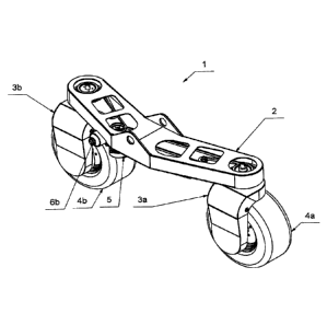
In accordance with the teachings herein, the axle with a portal suspension 3a
and 3b of
the wheels 4a and 4b has been developed, providing unrestricted 360 rotation.
Each portal suspension 3a and 3b accommodates an angular chain transmission 24
comprising a drive shaft 9, a driven shaft 10 and a link chain 11.
The drive chain 11 transmits the drive torque from the drive shaft 9 to the
driven shaft 10,
the link chain 11 being tensioned by a pulley angle system 12.
On the axle 1, portal suspensions 3a and 3b are provided with wheels 4a and
4b, a power
drive unit 5, swivel drive units 6a and 6b, swivel distribution systems 7a and
7b and travel
distribution systems 8a and 8b.
The swivel and travel distribution systems 7a, 7b and 8a, 8b are preferably
selected from
the group consisting of belts, V-belts, toothed belts, transmission chains,
gears, and the
like.
4
Date Recue/Date Received 2023-03-07
The drive units 5, 6a and 6b are preferably selected from the group consisting
of internal
combustion engines, hydraulic motors, electric motors, and the like.
The solution according to the teachings herein is characterized in particular
by the
following features for each portal suspension 3a and 3b:
In principle, the vertical longitudinal axis 13 of the drive shaft 9 in the
portal wheel
suspension 3a and 3b makes an angle with the horizontal axis 14 of the driven
shaft 10
in particular of 900
,
the portal wheel suspensions 3a and 3b due to its mounting into the axle 1 via
a bearing
flange 23 allow in principle unrestricted rotation around the longitudinal
axis 13 of the
drive shaft 9 over an angle range 360 .
For the sake of clarity, it is to be understood that the general terms and
technical terms
used in this specification generally have the following meanings:
The drive unit is a device for providing the drive torque for an axle and a
wheel
suspension, generally internal combustion engines, hydraulic motors, electric
motors, and
the like,
the distribution system represents mechanical machine elements for providing
the
transmission of the drive torque, selected from the group consisting of belts,
driving V-
belts, toothed belts, transmission chains, gears, and the like.
A preferred exemplary embodiment is shown in the accompanying drawings.
As shown in FIGS. 1 to 7, the axle 1, in particular of a universal carrier
frame, bears the
arm 2 of the axle 1, which may be, for example, a welded housing in which the
swivel
drive unit 6a of the front wheel 4a, the swivel drive unit 6b of the rear
wheel 4a, and the
power unit 5, are mounted.
These units may be, for example, electric motors, hydraulic motors, and the
like.
Date Recue/Date Received 2023-03-07
The front portal suspension 3a and the rear portal suspension 3h allow
unrestricted 3600
rotation by the swivel distribution systems 7a and 7b, which may be, for
example, chain
and belt torque distributions.
The drive torque for travel of the front wheel 4a is further distributed by
the travel
distribution system 8a of the front wheel 4a to the driven shaft 10 of the
front wheel 4a.
In the arm 2 of the axle 1, the front portal suspension 3a is mounted at one
end and the
rear portal suspension 3b is mounted at the other end, both of which
comprising a bearing
flange 23, wherein the mounting thereof in the axle 1 provides an unrestricted
360
rotation about the longitudinal axis 13 of the drive shaft 9.
Each portal suspension 3a and 3h comprises an angular chain transmission 24
comprising a drive shaft 9 and a driven shaft 10 which, by means of a link
chain 11,
transmit the drive torque from the power drive unit 5, which is formed, for
example, by a
hydraulic motor.
The substantially vertical longitudinal axis 13 of the drive shaft 9 makes an
angle a of 90
with the substantially horizontal longitudinal axis 14 of the driven shaft 10.
The link chain 11, which transmits the drive torque from the drive shaft 9 to
the driven
shaft 10, is tensioned by a pulley angular system 12.
The pulley angular system 12 is formed, for example, by a pair of tensioning
levers 15
with a pulley 16, which are mounted by means of a pin 19 in the portal
suspensions 3a
and 3b, the tensioning lever 15 allowing a rotary motion.
The pulley angular system 12 of the link chain 11 comprises a pair of wedges
22 that
press against the fitting pin 18 of the tensioning lever 15.
Each wedge 22, housed in the guide bar 21, is secured by one tension spring
20, which
is engaged in a respective portal suspension 3a, 3b.
6
Date Recue/Date Received 2023-03-07
The tension lever 15 comprising a pulley 16 further comprises a locating
compression
spring 17 which determines the tension of the link chain 11. The tension lever
15 is
connected to the given portal suspension 3a and 3b by a pin 19.
Upon loosening the link chain 11, one of the tensioning wedges 22 housed in
the guide
bar 21 is lowered by the force of one of the compression springs 20. The
fitting pin 18
transmits the above movement and tilts the tensioning lever 15 in order to
tension the link
chain 11 and to create an optimal tension clearance of the link chain 11.
The pulley angular system 12 of the link chain 11 comprises a compression
spring 17 on
the tensioning lever 15, which ensures optimum tension of the link chain 11.
INDUSTRIAL APPLICABILITY
According to the teachings herein, an axle has been developed, at the ends of
which the
portal suspensions are located, which by their mounting via the bearing flange
and due
to the swivel drive units allow unrestricted rotation about their longitudinal
axis of the drive
shaft within the angle of 360 .
The axle further includes a power drive unit that distributes drive torque
over the
distribution system to the drive shaft.
Each portal suspension comprises an angular chain transmission comprising a
drive shaft
and a driven shaft spaced at an angle of 90 to each other, the drive torque
being
transmitted by means of a link chain with a tensioning system.
The teachings herein may be employed in a low installation space for an axle
using an
angular chain transmission in the portal suspension of the wheel, and hence
may use
low-cost elements.
The teachings herein may provide for unrestricted rotation of the portal wheel
suspension
in the axle within an angle of 360 .
The angular chain transmission axle in the wheel suspension may find
application, for
example, in frames of cars or universal carriers.
7
Date Recue/Date Received 2023-03-07
List of reference numerals
1 - axle
2 - arm 2 of the axle 1
3a - front portal suspension
3b - rear portal suspension
4a - front wheel 4a of the front portal suspension 3a
4b - rear wheel 4b of the rear portal suspension 3b
- power drive unit
6a - swivel drive unit 6a of the front wheel 4a
6b - swivel drive unit 6a of the rear wheel 4b
7a - swivel distribution system 7a of the front wheel 4a
7b - swivel distribution system 7b of the rear wheel 4b
8a - travel distribution system 8a of the front wheel 4a
8b - travel distribution system 8b of the rear wheel 4b
9 - drive shaft
- driven shaft
11 - link chain
12 - pulley angular system 12 of the link chain 11
13 - longitudinal axis 13 of the drive shaft 9
14 - longitudinal axis 14 of the driven shaft 10
8
Date Recue/Date Received 2023-03-07
15 - tensioning lever
16 - pulley
17 - compression spring
18 - fitting pin
19 - pin
20 - tension spring
21 - guide bar
22 - wedge
23 - bearing flange
24 - angular chain transmission
a - angle a between the longitudinal axis 13 of the drive shaft 9 and
the
longitudinal axis 14 of the driven shaft 10
9
Date Recue/Date Received 2023-03-07