Note: Descriptions are shown in the official language in which they were submitted.
CA 03134252 2021-09-16
WO 2020/191167
PCT/US2020/023573
HIGH PERFORMANCE ELECTROMAGNETIC
MACHINE AND COOLING SYSTEM
CROSS-REFERENCE TO RELATED APPLICATIONS
[0001] This PCT International Patent Application claims the benefit of
and priority
to U.S. Provisional Patent Application Serial No. 62/820,529, filed March 19,
2019, titled
"High Performance Electromagnetic Machine" and U.S. Provisional Patent
Application
Serial No. 62/869,242, filed July 1, 2019, titled "Direct Cooling For Electric
Machines," the
entire disclosures of which are hereby incorporated by reference.
TECHNICAL FIELD
[0002] The present disclosure relates generally to electromagnetic
machines, and in
particular, electric machines having permanent magnet rotors and cooling
systems for the
electromagnetic machines.
BACKGROUND
[0003] Electromagnetic machines, such as electric motors or generators,
commonly
include a stationary part called a stator. Energy flows through the stator to
or from a
rotating component, such as a rotor that rotates. Stators commonly include one
or more
electrical conductors comprising a core wound in conductive wire. The rotating
component
typically includes one or more permanent magnets radially disposed on the
rotor. An
electrical current is applied or induced in the electrical conductors to
generate a magnetic
field that transfers energy to or from the rotating component, which may cause
the rotating
component to rotate. Such electromagnetic machines (e.g., referred to as
permanent magnet
machines or permanent magnet motors) typically yield desirable
characteristics, such as
high specific torque, high specific power, high efficiency, and low torque
ripple. However,
manufacturing costs of such electromagnetic machines (e.g., comprising
permanent
magnets) may be relatively high.
1
CA 03134252 2021-09-16
WO 2020/191167
PCT/US2020/023573
SUMMARY
[0004] This disclosure relates generally to electromagnetic machines.
[0005] Aspects of the disclosed embodiments include an electromagnetic
machine
that includes a stator that includes a back plate and a plurality of
electrical conductors
radially disposed on the back plate. The electromagnetic machine also includes
a rotor that
includes a body having an outer diameter corresponding to an inner diameter of
the stator
and at least one magnet having a first end disposed proximate the stator and a
second end
disposed opposite the first end. The electromagnetic machine also includes an
engaging
member disposed on a shaft that extends axially relative to the rotor, the
engaging member
being configured to engage at least one recessed portion of the rotor.
[0002] According to some embodiments, an electric machine comprises a
stator,
which includes a core. The core includes a yoke having a plurality of teeth
extending
radially from the yoke. The core defines a slot between two adjacent ones of
the teeth. A
first winding of electrically-conductive material extends through the slot
adjacent a first one
of the teeth. A second winding of electrically-conductive material extends
through the slot
adjacent a second one of the teeth. A cooling channel extends through the slot
and is
configured to convey a coolant fluid for removing heat from the stator.
[0003] According to some embodiments, an electric machine comprises a
stator,
which includes a core. The core includes a yoke having an annular cross-
section and a
plurality of teeth extending radially from the yoke. A slot is defined between
two adjacent
ones of the teeth. A winding of electrically-conductive material extends
through the slot. A
coil carrier of non-conductive material extends through the slot between the
winding and an
adjacent one of the teeth. The coil carrier defines a cooling channel
extending through the
slot between the winding and the adjacent one of the teeth. The cooling
channel is
configured to convey a coolant fluid for removing heat from the stator.
2
CA 03134252 2021-09-16
WO 2020/191167
PCT/US2020/023573
[0004] According to some embodiments, an electric machine comprises a
stator and
a rotor configured to rotate relative to the stator. An air gap is defined
between the rotor
and the stator. The rotor includes a body and a plurality of permanent magnets
disposed
upon the body and adjacent to the air gap. The rotor defines a trough
extending
circumferentially between adjacent ones of the permanent magnets. The trough
also
extends radially from the body toward the stator. A cooling channel extends
through the
trough and is configured to convey a coolant fluid.
[0005] According to some embodiments, an electric machine comprises a
stator and
a rotor configured to rotate about an axis. A heat pipe includes an evaporator
tube
extending axially through the rotor. The heat pipe also includes condenser
disposed at or
adjacent to an axial end of the rotor. The heat pipe is configured to absorb
heat from the
rotor by evaporating a refrigerant within the evaporator tube. The heat pipe
is also
configured to transfer the heat away from the rotor by condensing the
refrigerant to a liquid
within the condenser. The electric machine also includes a nozzle configured
to direct a
cooling fluid upon the axial end of the rotor for transferring heat from the
condenser.
[0006] According to some embodiments, an electric machine comprises a
stator and
a rotor that includes a rotor body configured to rotate about an axis. The
rotor defines a
plurality of recesses within the rotor, with each of the recesses extending
axially outwardly
from an inner surface of the rotor. Each of the recesses also define a ledge
that extends
generally circumferentially and which faces axially outwardly. In some
embodiments, one
or more of the recesses has a cross-sectional shape of a Christmas tree
comprising two or
more overlapping triangles.
[0001] According to some embodiments, an electric machine comprises a
stator and
a rotor configured to rotate with a shaft about an axis. At least one of the
stator and/or the
3
CA 03134252 2021-09-16
WO 2020/191167
PCT/US2020/023573
rotor defines a plurality of cooling channels that extend axially. A fan is
attached to an
axial end of the shaft and is configured to circulate air through the cooling
channels.
[0002] According to some embodiments, an electromagnetic machine
includes a
stator that includes a back plate and a plurality of electrical conductors
radially disposed on
the back plate. The electromagnetic machine also includes a rotor that
includes a body
having an outer diameter corresponding to an inner diameter of the stator and
at least one
magnet having a first end disposed proximate the stator and a second end
disposed opposite
the first end. The electromagnetic machine also includes an engaging member
disposed on
a shaft that extends axially relative to the rotor, the engaging member being
configured to
engage at least one recessed portion of the rotor.
[0003] According to some embodiments, an electric machine includes a
stator
including a core, the core including a yoke having a plurality of teeth
extending radially
from the yoke, the core defining a slot between two adjacent teeth of the
plurality of teeth.
The electric machine also includes a first winding of electrically-conductive
material
extending through the slot adjacent a first tooth of the plurality of teeth
and a second
winding of electrically-conductive material extending through the slot
adjacent a second
tooth of the plurality of teeth. The electric machine also includes a cooling
channel
extending through the slot and configured to convey a coolant fluid for
removing heat from
the stator.
[0004] According to some embodiments, an apparatus includes a stator
that includes
a back plate and a plurality of electrical conductors radially disposed on the
back plate and a
rotor configured to rotate relative to the stator and defining an air gap
between the rotor and
the stator. The rotor includes a body having an outer diameter corresponding
to an inner
diameter of the stator and of permanent magnets disposed upon the body and
adjacent to the
air gap. The rotor defines a trough extending circumferentially between
adjacent ones of
4
CA 03134252 2021-09-16
WO 2020/191167
PCT/US2020/023573
the plurality of permanent magnets, the trough extending radially from the
body toward the
stator. The apparatus also includes a cooling channel extending through the
trough and
configured to convey a coolant fluid and an engaging member disposed on a
shaft that
extends axially relative to the rotor, the engaging member being configured to
engage at
least one recessed portion of the rotor.
[0005] These and other aspects of the present disclosure are disclosed
in the
following detailed description of the embodiments, the appended claims, and
the
accompanying figures.
BRIEF DESCRIPTION OF THE DRAWINGS
[0006] The disclosure is best understood from the following detailed
description
when read in conjunction with the accompanying drawings. It is emphasized
that,
according to common practice, the various features of the drawings are not to-
scale. On the
contrary, the dimensions of the various features are arbitrarily expanded or
reduced for
clarity.
[0007] FIG. 1A generally illustrates a cross-sectional view of an
electric machine
according to the principles of the present disclosure.
[0008] FIG. 1B generally illustrates an enlarged section of the cross-
sectional view
of FIG. 1A showing a stator with fluid channels according to the principles of
the present
disclosure.
[0009] FIG. 1C generally illustrates an enlarged section of the cross-
sectional view
of FIG. 1A showing a rotor with a fluid channel according to the principles of
the present
disclosure.
[0010] FIG. 2 generally illustrates a partial cross-sectional view of a
stator of an
electric machine according to the principles of the present disclosure.
CA 03134252 2021-09-16
WO 2020/191167
PCT/US2020/023573
[0011] FIG. 3 generally illustrates a partial cross-sectional view of
the stator of FIG.
2 according to the principles of the present disclosure.
[0012] FIG. 4 generally illustrates a partial cross-sectional view of a
stator of an
electric machine according to the principles of the present disclosure.
[0013] FIG. 5 generally illustrates a partial cross-sectional view of an
electric
machine according to the principles of the present disclosure.
[0014] FIG. 6 generally illustrates an exploded view of parts of a
stator according to
the principles of the present disclosure.
[0015] FIG. 7 generally illustrates a partial cross-sectional view of a
stator within an
electric machine according to the principles of the present disclosure.
[0016] FIG. 8 generally illustrates a perspective schematic view of a
cooling
channel according to the principles of the present disclosure.
[0017] FIG. 9 generally illustrates a perspective schematic view of a
cooling
channel according to the principles of the present disclosure.
[0018] FIG. 10 generally illustrates a schematic diagram of a cooling
channel
according to the principles of the present disclosure.
[0019] FIG. 11 generally illustrates a schematic diagram of a cooling
channel
according to the principles of the present disclosure.
[0020] FIG. 12 generally illustrates cross-sectional view of an electric
machine
including a heat pipe within a rotor according to the principles of the
present disclosure.
[0021] FIG. 13A generally illustrates a cross-sectional view of an
electric machine
according to the principles of the present disclosure.
[0022] FIG. 13B generally illustrates an enlarged section of FIG. 13A.
[0023] FIG. 13C generally illustrates an alternative version of the
cross-sectional
generally illustrated in FIG. 13B.
6
CA 03134252 2021-09-16
WO 2020/191167
PCT/US2020/023573
[0024] FIG. 14 generally illustrates a cross-sectional view of an
electric machine
according to the principles of the present disclosure.
[0025] FIG. 15 generally illustrates a cross-sectional view of an
electric machine
according to the principles of the present disclosure.
[0026] FIG. 16A generally illustrates top view of an electromagnetic
machine
according to the principles of the present disclosure.
[0027] FIGS. 16B and 16C generally illustrate a top view of a portion of
a rotor of
according to the principles of the present disclosure.
[0028] FIG. 16D generally illustrates a top view of a portion of an
alternative rotor
according to the principles of the present disclosure.
DETAILED DESCRIPTION
[0029] The following discussion is directed to various embodiments of
the
invention. Although one or more of these embodiments may be preferred, the
embodiments
disclosed should not be interpreted, or otherwise used, as limiting the scope
of the
disclosure, including the claims. In addition, one skilled in the art will
understand that the
following description has broad application, and the discussion of any
embodiment is meant
only to be exemplary of that embodiment, and not intended to intimate that the
scope of the
disclosure, including the claims, is limited to that embodiment.
[0030] As described, typical electromagnetic machines comprising
permanent
magnets may be relatively expensive to manufacture. Accordingly,
electromagnetic
machines, such as those described herein, that achieve similar output
characteristics, as
typical electromagnetic machines, at a lower manufacturing cost, may be
desirable.
[0031] Further, thermal management, including heat dissipation, is an
important
design and operating aspect for electric machines, such as motors, generators,
or
motor/generators. Thermal management is especially important for electric
machines used
7
CA 03134252 2021-09-16
WO 2020/191167
PCT/US2020/023573
as traction motors in electrified vehicles, such as battery electric vehicles
(EVs) and plug-in
hybrid electric vehicles (PHEVs). Heat dissipation may be accomplished using a
variety of
different cooling devices, including passive devices such as heat sinks and
active devices
that may transfer heat away from the heat source using a moving fluid. Various
design
considerations affect the type of cooling device or devices that may be
employed. Some
primary design considerations include cost, packaging constraints, and
environmental
conditions.
[0032] According to some embodiments, electromagnetic machines described
herein
may be configured to deliver similar output characteristics within the similar
outer diameter,
length, input voltage, current, and thermal limits as typical electromagnetic
machines. In
some embodiments, the electromagnetic machines described herein may use
reduced
number of neodymium (NdFeB) permanent magnets.
[0033] In some embodiments, the electromagnetic machines described
herein may
provide an increased reluctance torque component. In some embodiments, the
electromagnetic machines described herein may include minimum end winding
length (e.g.,
due to concentrated winding, as will be described).
[0034] In some embodiments, the electromagnetic machines described
herein may
include a peak-peak torque ripple value less than 1% of a motor peak torque.
In some
embodiments, the electromagnetic machines described herein may include minimum
back
iron in the rotor and stator, which may reduce an amount of electrical steel
used in the rotor
and stator.
[0035] In some embodiments, the electromagnetic machines described
herein may
include an engaging member having a gear-like structure and comprising
aluminum or other
suitable material. The engagement member may be disposed on a shaft and may be
configured to engage the rotor to connect the rotor to the shaft.
8
CA 03134252 2021-09-16
WO 2020/191167
PCT/US2020/023573
100361 In some embodiments, the electromagnetic machines described
herein may
reduce magnet losses through axial magnet segmentation and/or radial magnet
segmentation. In some embodiments, the electromagnetic machines described
herein may
include a flux focusing arrangement in the rotor, which may result in an
increased flux
linkage with the stator. In some embodiments, the electromagnetic machines
described
herein may include an arrangement to hold magnets in the rotor from moving
upwards
without additional retaining structure.
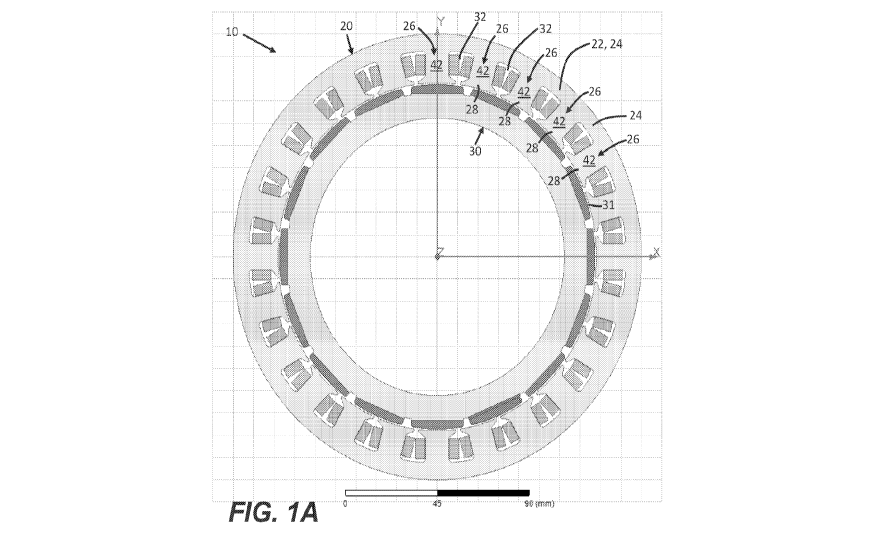
100371 FIG. lA is cross-sectional view of an electric machine 10
according to
embodiments of the disclosure. Specifically, the electric machine 10 includes
a stator 20
which comprises a core 22. In some embodiments, the core 22 is made from a
stack of
laminations of material. The core 22 may be made of steel, such as silicon
steel, to provide
a relatively low reluctance. The core 22 includes a yoke 24 having a ring-
shaped cross-
section, as shown in FIG. 1A. The core 22 also includes a plurality of teeth
26 that extend
radially from the yoke 24. The teeth 26 each extend between the yoke 24 and a
distal end
28 that is radially spaced apart from the yoke 24. The electric machine 10
also includes a
rotor 30 that is configured to rotate, and which defines an air gap 31 between
the rotor 30
and the stator 20. The core 22 of the stator 20 also defines slots 32 between
adjacent ones
of the teeth 26.
100381 In some embodiments, and as shown in FIG. 1A, the electric
machine 10 is
configured as an internal rotor machine, and the teeth 26 extend radially
inwardly toward
the rotor 30. In other embodiments (not shown in the FIGS), the teeth 26
extend radially
outwardly toward an external rotor that may surround the stator 20.
100391 FIG. 1B is an enlarged section of the cross-sectional view of
FIG. 1A,
including a first tooth 26a and a second tooth 26b, where each of the first
and second teeth
26a, 26b are ones of the teeth 26 which are adjacent to one another. FIG. 1B
shows one of
9
CA 03134252 2021-09-16
WO 2020/191167
PCT/US2020/023573
the slots 32 between the first tooth 26a and the second tooth 26b. FIG. 1B
also shows a first
winding 34 of electrically-conductive material extending through the slot 32
adjacent to the
first tooth 26a, and a second winding 36 of electrically-conductive material
extending
through the slot 32 adjacent to the second tooth 26b. The windings 34, 36 may
be made of
copper or a copper alloy, although other materials may be used to form the
windings. The
windings 34, 36 may take the form of a wire that is wound around one or more
of the teeth
26. Alternatively, the windings 34, 36 may take the form of one or more bars
or rods.
[0040] As also shown in FIG. 1B, a cooling channel 40, 40', 40" may
extend
through the slot 32 to convey a coolant fluid for directly removing heat from
the stator 20.
In some embodiments, each of the slots 32 may define an upper cavity 42 that
extends
through the slot 32 between the distal ends 28 of the teeth 26a, 26b and on a
side of the first
winding 34 and the second winding 36 that is radially adjacent to the rotor
30. The cooling
channel 40, 40', 40" may take the form of a first cooling channel 40 that
extends through
the upper cavity 42.
[0041] In some embodiments, and as also shown in FIGS. lA and 1B, each
of the
teeth 26a, 26b may include a trunk 44 with a generally rectangular cross-
section extending
radially from the yoke 24 to the distal end 28. The first winding 34 and the
second winding
36 together define a wedge-shaped space 46 therebetween and within the slot
32. The
cooling channel 40, 40', 40" may take the form of a second cooling channel 40'
that
extends through the wedge-shaped space 46 between the first and second
windings 34, 36.
Alternatively or additionally, the slot 32 may include a bottom cavity 48 that
extends along
a floor 29 of the slot 32 adjacent the yoke 24. The bottom cavity 48 that
extends radially
away from floor 29 to one of the first winding 34 and/or the second winding
36. The
cooling channel 40, 40', 40" may take the form of a third cooling channel 40"
that extends
through the bottom cavity 48.
CA 03134252 2021-09-16
WO 2020/191167
PCT/US2020/023573
[0042] In some embodiments, the cooling channel 40, 40', 40" may
comprise one
or more of the first, second, and/or the third cooling channels 40, 40', 40".
Furthermore,
the cooling channel 40, 40', 40- may include a conduit, such as a tube of
liquid-tight
material. Such a tube of liquid-tight material may include, for example,
plastic, rubber, or a
composite material. In some embodiments, one or more portions of the cooling
channels
40, 40', 40" may be defined entirely or in part by the core 22 and/or one of
the windings
34, 36 of the stator 20. In some embodiments, a first seal 38 of liquid-tight
material may
define some or all of the cooling channel 40, 40', 40-. For example, and as
shown in FIG.
1B, the first seal 38 may extend between the distal ends 28 of adjacent ones
of the teeth 26a,
26b in order to enclose the slot 32 and to prevent coolant fluid from
migrating out of the slot
32.
[0043] FIG. 1C is an enlarged section of the cross-sectional view of
FIG. 1A
showing the rotor 30 with a fourth fluid channel 40" ' according to an aspect
of the
disclosure. Specifically, the rotor 30 includes a body 50 defining a
peripheral edge 52
facing the stator 20. The rotor also includes a plurality of permanent magnets
54 disposed
upon the body 50 and about the peripheral edge 52 of the rotor 30 and adjacent
to the air
gap 31. The rotor 30 defines a trough 56 that extends circumferentially
between adjacent
ones of the permanent magnets 54. The trough 56 extends radially from the body
50 toward
the stator 20. A fourth cooling channel 40" may extend through the trough 56
in the rotor
30 to convey a coolant fluid therethrough for directly cooling the rotor 30.
In some
embodiments, some or all of the permanent magnets 54 may be inset within the
body 50 of
the rotor 30. In the example embodiment of FIGS. 1A-1C, the electric machine
10 is
configured as an internal rotor machine, with the permanent magnets 54 mounted
on a
radially outside surface of the rotor 30. In other embodiments (not shown in
the FIGS), the
permanent magnets 54 may extend radially inwardly toward an internal stator
that is
11
CA 03134252 2021-09-16
WO 2020/191167
PCT/US2020/023573
encircled by the rotor 30. In some embodiments, the fourth fluid channel 40"
includes a
conduit of a material having a high reluctance, such as, for example plastic
or composite
material. Such material may provide advantages over materials having a lower
reluctance,
such as metals. For example, a conduit having a relatively high reluctance may
cause more
of the magnetic flux from the permanent magnets to be directed radially
outwardly or
inwardly, which can provide improved performance of the electric machine 10.
[0044] In some embodiments, a second seal 58 of liquid-tight material
may define
some or all of the trough 56. For example, and as shown in FIG. 1C, the second
seal 58
may extend between adjacent ones of the permanent magnets 54 in order to
enclose the
trough 56 and to prevent coolant fluid from migrating out of the trough 56.
[0045] The coolant fluid that is circulated through the cooling channels
40, 40',
40", 40" ' may include a refrigerant configured to remove heat through a phase
change.
Alternatively or additionally, the coolant fluid may include a coolant liquid
such as, for
example, water, methanol, glycol, or a mixture of two or more different
coolant liquids.
[0046] FIGS. 2-3 are partial cross-sectional views of a stator 20
according to aspects
of the disclosure. The stator 20 shown in FIGS. 2-3 may have a similar
construction to the
stator 20 of FIGS. 1A-1C, with a core 22 that includes a yoke 24 and a
plurality of teeth 26
extending radially inwardly from the yoke 24. The core 22 may be formed, for
example,
from laminated steel. Specifically, FIGS. 2-3 show two adjacent teeth 26 the
stator 20, with
each of the teeth 26 having an elongated trapezoidal shape extending radially
inwardly from
a yoke 24. A slot 32 having parallel sides is defined between the two adjacent
teeth 26 the
stator 20 with windings 34, 36 extending through the slot 32. FIGS. 2-3 show
an apparatus
for forming the teeth 26 by compressing the teeth 26 between a support force
100 that acts
radially upon the yoke 24 and a forming force 102 that acts radially upon the
teeth 26. The
support force 100 and the forming force 102 act in opposite directions to
compress and
12
CA 03134252 2021-09-16
WO 2020/191167
PCT/US2020/023573
deform the teeth 26 to enclose the slot 32. Specifically, the forming force
102 acts upon a
die 104 to deform and spread the distal ends 28 of the teeth 26. A spacer 106
lines an inner
surface of the slot 32 to prevent the windings 34, 36 from contacting the core
22 of the
stator 20.
[0047] As also shown in FIGS. 2-3, a first cooling channel 40 extends
through an
upper cavity 42 in the slot 32 between the distal ends 28 of the teeth 26. A
third cooling
channel 40" extends through a bottom cavity 48 in the slot 32 along the yoke
24 and
radially away from the yoke 24 to one of the windings 34, 36. The electric
machine 10 may
include one or more of the cooling channels disclosed. The cooling channel or
channels 40,
40', 40" may be configured differently than as shown. For example, a cooling
channel 40,
40', 40" may be disposed between the windings 34, 36.
[0048] FIG. 4 is a partial cross-sectional view of a stator of an
electric machine
according to aspects of the disclosure. Specifically, FIG. 4 is a variation of
the stator 20
shown in FIG. 1B, in which the first winding 34 and the second winding 36
together define
a wedge-shaped space 46 therebetween and within the slot 32. Similarly to the
arrangement
of FIG. 1B, the cooling channel 40, 40', 40" in FIG. 4 takes the form of a
second cooling
channel 40' that extends through the wedge-shaped space 46 between the first
and second
windings 34, 36. In FIG. 4, a portion of each of the windings 34, 36 extends
along the floor
29 of the slot 32 to surround the wedge-shaped space 46.
[0049] FIG. 5 is a partial cross-sectional view of an electric machine
according to
aspects of the disclosure. In some embodiments, and as shown in FIG. 5, the
stator 20 of an
electric machine 10 includes a potting material 110 that envelopes the
windings 34, 36. The
potting material 110 may hold the windings 34, 36 and prevent the windings 34,
36 from
moving relative to the core 22 of the stator 20. The potting material 110 may
be, for
example, a non-conductive epoxy, resin, and/or plastic material. In some
embodiments, and
13
CA 03134252 2021-09-16
WO 2020/191167
PCT/US2020/023573
as shown in FIG. 5, a cooling channel 40 extends through the potting material
110 within
the slots 32 for conveying a coolant fluid therethrough to remove heat from
the stator 20.
FIG. 5 shows one example arrangement of the cooling channels 40. However, each
slot
may have one or more cooling channels 40 that may extend through a
corresponding one of
the slots 32 in any suitable location. For example, the cooling channels 40
may be disposed
adjacent to the rotor 30, as shown. Alternatively or additionally, the cooling
channels 40
may be disposed adjacent to the yoke 24 of the stator 20 and/or within or
amongst the
windings 34, 36.
[0050] FIG. 6 is an exploded view of parts of a stator 20 according to
aspects of the
disclosure. Specifically, the stator 20 includes a core 22, which may be
formed of steel. A
coil carrier 120 surrounds the core 22 to hold one or more winding coils and
to prevent the
winding coils from directly contacting the core 22. In some embodiments, and
as shown in
FIG. 6, the coil carrier 120 includes a first carrier shell 122 and a second
carrier shell 124
that together surround the core 22 of the stator 20. The carrier shells 122,
124 may
surround the core 22 of the stator 20 in a clamshell arrangement.
[0051] FIG. 7 is a partial cross-sectional view of a stator 20 within an
electric
machine 10 according to aspects of the disclosure. Specifically, the stator 20
includes a
core 22, which may be formed, for example, of steel. The core 22 includes a
yoke 24
having an annular cross-section and a plurality of teeth 26 extending radially
from the yoke
24. Adjacent ones of the teeth 26 define a slot 32 therebetween. A set of
windings 34, 36
of electrically-conductive material extends through the slot 32. The windings
34, 36 may
be, for example, metal wire or bars. The windings 34, 36 may be made of copper
with a
coating of an electrically insulating material. The coil carrier 120 includes
a wall portion
130 that extends through the slot 32 and adjacent one of the teeth 26. The
coil carrier 120
may be made of electrically non-conductive material in order to hold the
windings 34, 36
14
CA 03134252 2021-09-16
WO 2020/191167
PCT/US2020/023573
apart from the teeth 26 of the core 22. Alternatively or additionally, the
coil carrier 120
may include a floor portion 132 that extends through the slot 32 and adjacent
the yoke 24 of
the core 22.
[0052] The wall portions 130 of the coil carrier 120 each define a first
cooling
channel 140 and a second cooling channel 142. The floor portion 132 of the
coil carrier 120
defines a third cooling channel 144. Each of the cooling channels 140, 142,
144 is
configured to convey a coolant fluid for removing heat from the stator 20. The
diagram of
FIG. 7 is merely an example arrangement, and the coil carrier 120 may include
any
configuration of the cooling channels 140, 142, 144 including any one or more
of the
cooling channels 140, 142, 144 shown. For example, the wall portions and/or
the floor
portions 132 may each include any number of the cooling channels 140, 142,
144. In some
embodiments, other portions of the coil carrier 120, such as portions of the
first and second
carrier shells 122, 124 that extend outside of the slots 32 may also define
fluid conduits for
conveying coolant fluid. Those fluid conduits may, for example, serve as
headers for
directing fluid into and out of the cooling channels 140, 142 in the wall
portions 130 of the
coil carrier 120.
[0053] In some embodiments, one or more of the cooling channels 40, 40',
40",
40" 140, 142, 144 within the electric machine 10 may be configured as
circulating cooling
channels 200 having both a supply conduit 202 and a return conduit 204 and
configured to
convey coolant fluid through the supply conduit 202 and back from the return
conduit 204.
In some embodiments, the circulating cooling channel 200 includes the supply
conduit 202
and the return conduit 204 adjacent and parallel to one another, with a
partition 206
separating the supply conduit 202 from the return conduit 204. In some
embodiments, and
as shown in FIGS. 8-9, the partition 206 defines one or more passages 208 for
conveying
the fluid from the supply conduit 202 into the return conduit 204 in the form
of one or more
CA 03134252 2021-09-16
WO 2020/191167
PCT/US2020/023573
fluid jets 210. The fluid jets 210, which may also be called impinging jets,
contact a target
surface 212, which may be a predetermined region within the return conduit
204. The fluid
jets 201 thus remove heat from an outside surface 214 of the circulating
cooling channel
200, and particularly where the outside surface 214 is adjacent and opposite
to the target
surface 212. This configuration may be especially useful where the outside
surface 214 is
in direct thermal communication with a heat source, such as a winding or where
the outside
surface 214 is in direct thermal communication with a component that is
sensitive to
temperature, and which can most benefit from having a regulated temperature.
For
example, the outside surface 214 may be placed in thermal communication with a
permanent magnet in order to maintain the permanent magnet within a
predetermined
temperature range, even when other portions of the electric machine 10 have a
higher
temperature.
[0054] FIG. 8 shows an example embodiment of a circulating cooling
channel 200
having the supply and return conduits 202, 204 extending parallel and adjacent
to one
another. FIG. 9 shows another example embodiment of a circulating cooling
channel 200 in
which the supply conduit 202 and the return conduit 204 are coaxial, with the
supply
conduit 202 disposed within the return conduit 204, and with the partition 206
having a
closed cross-section to define the return conduit 204 as a central region
bounded by the
partition 206.
[0055] In some embodiments, one or more cooling channels 40, 40', 40",
40" 140,
142, 144 within the electric machine 10 may be configured as counter-flowing
cooling
channels 220 having two or more streams 222, 224 of coolant fluid that are
configured to
converge from opposite directions at a convergence region 226 to generate a
turbulence
within the coolant fluid.
16
CA 03134252 2021-09-16
WO 2020/191167
PCT/US2020/023573
[0056] The turbulence may enhance cooling by increasing the
effectiveness of the
coolant fluid to remove heat from the one or more cooling channels 40, 40.,
40", 40¨ 140,
142, 144. For example, turbulence may cause a convection cooling effect in
which more
heat is transferred to the cooling fluid from an interior wall of the one or
more cooling
channels 40, 40', 40", 40" 140, 142, 144 than would be transferred as a result
of a less
turbulent (e.g. laminar) flow.
[0057] FIG. 10 shows one example configuration of a counter-flowing
cooling
channel 220 having a first supply line 230 configured to convey the first
stream 222 of the
coolant fluid to the convergence region 226. The counter-flowing cooling
channel 220 of
FIG. 10 also has a second supply line 232 configured to convey the second
stream 224 of
the coolant fluid to the convergence region 226, where the two streams 222,
224 meet from
opposite directions to generate turbulent flow. The example counter-flowing
cooling
channel 220 of FIG. 10 also includes a first return line 234 and a second
return line 236 for
conveying the coolant fluid from the convergence region 226. In some
embodiments, and
as shown in the example configuration of FIG. 10, one or more blocks 238 or
other
structures may be provided to direct the coolant fluid into the convergence
region 226 and
to interrupt a direct path between one of the supply lines 230, 232 and a
corresponding one
of the return lines 234, 236.
[0058] FIG. 11 shows another example configuration of a counter-flowing
cooling
channel 220 having the first and second supply lines 230, 232 each configured
to convey a
corresponding one of the streams 222, 224 of the coolant fluid to the
convergence region
226. Specifically, the example configuration of FIG. 11 includes the first
stream 222 and
the second stream 224 converging head-on (i.e. 180 degrees to one-another) at
the
convergence region 226. The example configuration of FIG. 11 also includes a
pair of
return lines 234, 236 configured to remove the coolant fluid from the
convergence region
17
CA 03134252 2021-09-16
WO 2020/191167
PCT/US2020/023573
226. In some embodiments, the streams 222, 224 may converge at a right angle
or at an
oblique angle to one-another.
[0059] The example embodiments of FIGS. 10-11 each include two supply
lines
230, 232 and two return lines 234, 236. However, a counter-flowing cooling
channel 220
may have any number of two or more supply lines 230, 232 and any number of
return lines
234, 236. For example, in some embodiments, the counter-flowing cooling
channel 220
may include three or more of the supply lines 230, 232 each configured to
convey a
corresponding one of the streams 222, 224 of the coolant fluid to the
convergence region
226.
[0060] FIG. 12 is cross-sectional view of an electric machine 300
including a heat
pipe 310 within a rotor 306 according to embodiments of the disclosure.
Specifically, the
electric machine 300 includes a stator 302 disposed within a housing 304 and a
rotor 306
configured to rotate about an axis A and to turn an output shaft 308. The
rotor 306 includes
a heat pipe 310 configured to remove heat from the rotor 306. The heat pipe
310 includes
an evaporator tube 314 extending axially through the rotor 306. The heat pipe
310 also
includes a condenser 316 disposed at or adjacent to an axial end 318 of the
rotor 306. The
heat pipe 310 is configured to absorb heat from the rotor 306 by evaporating a
refrigerant
within the evaporator tube 314 and to transfer the heat away from the rotor
306 by
condensing the refrigerant to a liquid within the condenser 316.
[0061] As also shown in FIG. 10, the electric machine 300 includes a
supply line
322 in fluid communication with a header 324 within the housing 304 and
configured to
deliver a cooling fluid into the header 324. The header 324 includes one or
more nozzles
326, which are each configured to direct one or more streams 330 of the
cooling fluid upon
the axial end 318 of the rotor 306 for transferring heat from the condenser
316. The cooling
fluid used within the electric machine 300 of FIG. 12 may be an oil. Other
types of cooling
18
CA 03134252 2021-09-16
WO 2020/191167
PCT/US2020/023573
fluids may be used, such as, for example, methanol or glycol. The electric
machine 300
may include any number of the heat pipes 310, and any number of the nozzles
326. The
nozzles 326 and/or the headers 324 may be formed directly into the housing 304
and/or the
supply lines 322. The electric machine 300 may also include a drain or a
return line (not
shown) for collecting the cooling fluid within the housing 304. Other
equipment, such as a
reservoir and a pump for circulating the cooling fluid may also be included.
[0062] In some embodiments, the evaporator tube of the 314 of the heat
pipe 310
may carry a coolant fluid such as water, methanol, and/or glycol instead of a
refrigerant.
The condenser 316 may function as a heat exchanger to transfer heat from the
coolant fluid
within the heat pipe 310 to a cooling fluid, such an oil, that is sprayed
thereupon by the
nozzles 326.
[0063] FIGS. 13A-13B show a cross-sectional view of an electric machine
10
according to embodiments of the disclosure. Specifically the electric machine
10 includes a
rotor 30 having a rotor body 350. The rotor body 350 may be made of steel,
such as silicon
steel, which may be called "electrical steel" to provide a relatively low
reluctance. The
rotor body 350 holds a plurality of permanent magnets 54 spaced at regular
intervals
circumferentially. The rotor body 350 also defines recesses 352, with each of
the recesses
352 disposed between two of the permanent magnets 52. Each of the recesses 352
extends
axially outwardly from an inner surface of the rotor 30. Each of the recesses
352 has a
cross-sectional shape of a Christmas-tree comprising two or more overlapping
triangles
defining ledges 354 that extend generally circumferentially and which face
axially
outwardly.
[0064] The shaft 308 is disposed within the rotor body 350 with the
rotor 30
completely surrounding the shaft 308. The shaft 308 includes a plurality of
protrusions 356,
with each of the protrusions 356 having a cross-sectional shape that is
complementary to all
19
CA 03134252 2021-09-16
WO 2020/191167
PCT/US2020/023573
or part of corresponding ones of the recesses 352 of the rotor body 350,
causing the rotor
body 350 to latch onto the shaft 308. The recesses 352 may extend for an axial
length of the
generally cylindrical rotor 30 such that they function as internal splines.
Similarly, the
protrusions 356 may extend for an axial length of the shaft 308 such that they
function as
external splines. The protrusions 356 and recesses 352 may The interaction of
the ledges
354 of the rotor body 350 against corresponding portions of the protrusions
356 on the shaft
308 may bias the rotor body 350 inwardly and provide extra strength to the
rotor 30. It
should be appreciated that the recesses 352 and/or the protrusions 356 may be
formed with
other cross-sections that may or may not include ledges 354. For example, the
recesses 352
may be shaped as a T or a cross (+). FIG. 13C shows a variation of the design
of FIG. 13B,
where the recess 352 is shaped as three overlapping triangles defining two
ledges 354
radially spaced apart from one another.
[0065] FIG. 14 is a cross-sectional view of an electric machine 10
according to
embodiments of the disclosure. Specifically, FIG. 14 shows an electric machine
10 with a
rotor 30 that is similar or identical to the rotor 30 of FIGS. 13A - 13B. The
shaft 308 of
FIG. 14 is formed as a hollow tube defining a center bore 366 that may be used
to convey
cooling fluid. For example, one or more second supply channels 368 may convey
cooling
fluid axially outwardly from the center bore 366. Additionally or
alternatively, one or more
second return channels 370 may convey cooling fluid axially inwardly toward
the center
bore 366.
[0066] In some embodiments, one or more fluid channels may extend
through one
or more of the recesses 352 for cooling the rotor 30. The fluid channels may
provide for
circulation of a cooling fluid such a coolant liquid of gas or refrigerant.
The fluid channels
may include air space or an evaporator, such as a heat pipe. The one or more
fluid channels
may be shaped as a rod with a cross-sectional shape that is complementary to
all or part of
CA 03134252 2021-09-16
WO 2020/191167
PCT/US2020/023573
corresponding ones of the recesses 352 of the rotor body 350. In some
embodiments, fluid
channels may extend through some of the recesses 352, and protrusions 356 of
the shaft 308
may extend through other ones of the recesses 352. For example, protrusions
356 of the
shaft 308 may extend through every second or every third one the recesses 352,
with fluid
channels extending through the remaining ones of the recesses 352.
Additionally or
alternatively, fluid channels may extend through one or more of the
protrusions 356 of the
shaft 308. In some embodiments, a passive cooling material, such as a solid
potting
material, may be disposed within one or more of the recesses 352.
[0067] In some embodiments, relatively cold coolant, such as automatic
transmission fluid (ATF), oil, water, glycol, methanol, or another liquid may
pass through
one or more first supply channels 360 in the shaft 308 into contact with one
or more of the
permanent magnets 54 or with a portion of the shaft 308 adjacent to and in
thermally
conductive contact with one or more of the permanent magnets 54. The coolant
may be
heated and then flow away from the one or more of the permanent magnets 54 via
one or
more first return channels 362 in the shaft 308.
[0068] In some embodiments, a cooling fluid may be sprayed upon an axial
end of
the rotor 30, which may convey heat away from one or more of the permanent
magnets 54,
which may be transferred via thermally conductive material, such as cooling
fluid in the
recesses 352 of the rotor body 350.
[0069] In some embodiments, a fan may be attached to an axial end of the
shaft 308
that is configured to circulate air through the rotor 30. For example, the fan
may pull air
through one or more of the recesses 352 of the rotor body 350 and expel the
air radially
outwardly. The fan may be shaped as a disc that may include one or more axial
blades
configured to direct the air axially outwardly as the fan is rotated with the
shaft 308.
21
CA 03134252 2021-09-16
WO 2020/191167
PCT/US2020/023573
[0070] One or more of the techniques described in the present disclosure
may be
applied to an electric machine 10 with a wound rotor, such as a wound field
synchronous
machine with copper windings in the rotor 30. FIG. 15 is a cross-sectional
view of an
electric machine 10 according to embodiments of the disclosure. Specifically,
the stator 20
of the electric machine 10 includes a rotor body 350 that defines a plurality
of rotor slots
376, with each of the rotor slots 374 holding two rotor windings 376. A rotor
gap 378
extends between two rotor windings 376. The rotor gap 378 may result from
manufacturing
limitations in winding and/or inserting the rotor windings 376 into the rotor
slots 374.
Hence, this rotor gap 378 could be used for one or more of the cooling
techniques discussed
above with reference to the stator 20.
[0071] FIG. 16A generally illustrates a top view of an electromagnetic
machine 410
according to the principles of the present disclosure. The electromagnetic
machine 410 may
include any suitable electromagnetic machine, such as an electric motor,
generator, or other
suitable electromagnetic machine. The electromagnetic machine 410 may include
features
similar to or different from other machines described herein. The
electromagnetic machine
410 includes a stationary component, such as a stator 420 and a rotatable or
moveable
component, such as a rotor 430. As described, energy flows through the stator
420 to or
from the rotor 430, causing the rotor 430 to rotate.
[0072] The stator 420 includes a back plate 422. The back plate 422 may
comprise
any suitable material, such as iron or other suitable material. The back plate
422 includes a
substantially circular profile having an outer diameter and an inner diameter.
The inner
diameter may define a bore that is configured to receive the rotor 430.
[0073] The stator 420 includes a plurality of electrical conductors 424
comprising a
magnetic core that includes one or more magnetic components. The electrical
conductors
424 are disposed in corresponding recesses 426 radially disposed on the back
plate 422.
22
CA 03134252 2021-09-16
WO 2020/191167
PCT/US2020/023573
The magnetic core of the electrical conductors 424 may be wound in one or more
windings
of conductive wire, such as copper wire or other suitable conductive wire.
[0074] The electrical conductor 424 windings may include concentrated
windings
having a relatively reduced or minimum end winding length. The concentrated
windings
may include a coil span of 1, which may reduce the end-winding length relative
to other
typical windings, such as distributed windings. Additionally, or
alternatively, the
concentrated windings having a coil span of 1 which may result in relatively
high stator slot
fill factor and a relatively low stator winding resistance and/or phase. A
relatively low
resistance may result in relatively low stator copper losses and relatively
high operating
efficiency.
[0075] In some embodiments, the back plate 422 of the stator 420 may
include
reduced or minimum back iron, which may reduce an amount of steel or other
material used
in the back plate 422 and/or the stator 420. Additionally, or alternatively,
the concentrated
windings of the electrical conductors 424 may provide a relatively short flux
path, which
allows for the back plate 422 to include a reduced back iron length (e.g.,
compared to
stators having distributed windings).
[0076] In some embodiments, the rotor 430 includes a body 432 comprising
a
substantially circular profile having an outer diameter that corresponds to
the inner diameter
of the stator 420. Additionally, or alternatively, the rotor 430 includes an
inner diameter
defining a central bore. The body 432 may comprise a non-conductive material,
such as
aluminum or other suitable material. In some embodiments, the body 432
includes one or
more apertures 434 radially deposed around the inner diameter of the body 432.
[0077] The rotor 430 includes one or more magnets 436 radially disposed
on the
body 432. The magnets 436 may include permanent magnets or other suitable
magnet. For
example, the magnets 436 may include neodymium (NdFeB) magnets, ferrite
magnets, or
23
CA 03134252 2021-09-16
WO 2020/191167
PCT/US2020/023573
other suitable magnets. The magnets 436 are disposed in corresponding recesses
438 of the
body 432. The recesses 438 extend from proximate the inner diameter of the
body 432 to
proximate the outer diameter of the body 432.
[0078] FIGS. 16B and 16C generally illustrate a top view of a portion of
the rotor
430. In some embodiments, magnets 436 include a first end 436-1 disposed
proximate an
outer portion 452 of the rotor 430 and a second end 436-2 disposed proximate
the inner
diameter of the rotor 430 (e.g., opposite the first end 436-1). In some
embodiments, the
first end 436-1 may include a width dimension that is smaller than a width
dimension of the
second end 436-2. For example, the magnets 436 may include a trapezoidal
profile, such
that respective first ends 436-1 are relatively narrower than respective
second ends 436-2.
[0079] Accordingly, the recesses 438 may include a profile corresponding
to the
profile of the magnets 436, such that the recesses 438 retain the magnets 436
and/or restrict
movement (e.g., without additional material or structure) of the magnets 436
toward the
outer portion 452 of the rotor 430.
[0080] In some embodiments, the outer portion 452 of the rotor 430 may
be
continuous or may be segmented. For example, as is generally illustrated in
FIG. 16D, the
outer portion 452 may be segmented, such that the outer portion 452 defines
air gaps 454
proximate respective first ends 436-1 of respective magnets 436. Additionally,
or
alternatively, air gaps 456 may be defined by the rotor 430, opposite the air
gaps 454. The
air gaps 456 may be disposed proximate respective second ends 436-2 of
respective
magnets 436.
[0081] In some embodiments, as is generally illustrated in FIG. 16C, the
magnets
436 may be segmented into a plurality of segments 458. For example, the
magnets 436 may
be axially and/or radially segmented. Segmenting the magnets 436 may reduce
magnet
loss. In operation, eddy currents in the magnets 436 flow perpendicular to
magnet flux of
24
CA 03134252 2021-09-16
WO 2020/191167
PCT/US2020/023573
the magnets 436. Accordingly, radial and axial segmentation of the magnets 436
may
prevent a continuous flow of eddy currents.
[0082] In some embodiments, the rotor 430 may provide relatively
increased
reluctance torque component that may be a result of the placement of the
magnet 436 in the
rotor 430 and a flux focusing arrangement of the rotor 430. This may provide
for an
increase in d-axis inductance and decrease in q-axis inductance, which may
improve a
saliency ratio that is typically near unity for stators having concentrated
winding.
Accordingly, the rotor 430 may include a fewer number of magnets 436 than
typical rotors,
which may lower the manufacturing costs associated with the rotor 430.
[0083] The electromagnetic machine 410 may include an engaging member
440
having a dimeter that corresponds to the inner diameter of the rotor 430. The
engaging
member 440 may be centrally disposed in the electromagnetic machine 410 and
may be
configured to engage and/or be connected with a shaft 450 that is axially
disposed within
the central bore of the rotor 430, which may provide a relatively high flux
linkage with the
stator 420. The engaging member 440 may include a gear like structure and may
comprise
a non-conductive material, such as aluminum, or other suitable non-conductive
material.
The arrangement of the engaging member 440 may allow for relatively less
material in the
rotor 430 (e.g., less steel used to manufacture the rotor 430).
[0084] The engaging member 440 may include a plurality of engaging
components
442 radially disposed around the engaging member 440. The engaging components
442
include a profile that corresponds to a profile of the apertures 434 of the
rotor 430. In some
embodiments, the engaging components 442 are configured to engage the
apertures 434 of
the rotor 430, such that the rotor 430 is in mechanical communication with the
shaft 450,
via the engaging member 440.
CA 03134252 2021-09-16
WO 2020/191167
PCT/US2020/023573
[0085] In operation, an electrical current is applied or induced in the
electrical
conductors 424 of the stator 420 to generate a magnetic field that transfers
energy to or from
the magnets 436 of the rotor 430, which may cause the rotor 430 to rotate
about the shaft
450, via the engaging member 440. In some embodiments, the magnets 436 may be
retained or restricted from movement by a portion of the engaging member 440.
This may
direct magnetic flux generated by magnets 436 toward the air gap 454, the air
gap 456, the
stator 420, or a combination thereof Additionally, or alternatively, air
flowing through the
electromagnetic machine 410 resulting from rotation of the rotor 430 may be
forced or
directed toward the air gaps 454 and/or the air gaps 456, which may provide
natural cooling
for the rotor 430 during operation.
[0086] In some embodiments, the electromagnetic machine 410 may output
a
peak-peak torque ripple value less than 1% of a motor peak torque.
Additionally, or
alternatively, the recesses 438 of the rotor 430, magnetic poles of respective
magnets 436,
and/or phases of the respective magnets 436 may provide relatively lower
torque ripple,
relatively lower forces, and relatively lower cogging torque. In some
embodiments,
segmenting the magnets 436 axially and/or skewing or adjusting a position of
the segments
458 of each respective magnet 436 by a relatively small angle for each segment
458, may
decrease the torque ripple and cogging torque significantly. In some
embodiments, the
spoke like placement of the magnets 436 in the rotor 430 may provide a
relatively lower
torque ripple and cogging torque.
[0087] In some embodiments, an electromagnetic machine includes a stator
that
includes a back plate and a plurality of electrical conductors radially
disposed on the back
plate. The electromagnetic machine also includes a rotor that includes a body
having an
outer diameter corresponding to an inner diameter of the stator and at least
one magnet
having a first end disposed proximate the stator and a second end disposed
opposite the first
26
CA 03134252 2021-09-16
WO 2020/191167
PCT/US2020/023573
end. The electromagnetic machine also includes an engaging member disposed on
a shaft
that extends axially relative to the rotor, the engaging member being
configured to engage
at least one recessed portion of the rotor.
[0088] In some embodiments, the first end of the at least one magnet has
a width
that is smaller than a width of the second end of the at least one magnet. In
some
embodiments, the at least one magnet includes a ferrite magnet. In some
embodiments, the
at least one magnet includes a neodymium magnet. In some embodiments, the body
of the
rotor includes a non-conducting material. In some embodiments, the non-
conducting
material includes aluminum. In some embodiments, the engaging member includes
a non-
conducting material. In some embodiments, the non-conducting material includes
aluminum. In some embodiments, the engaging member is configured to direct
flux
generated by the at least one magnet toward a corresponding air gap in the
rotor. In some
embodiments, the first end of the at least one magnet includes a trapezoidal
profile.
[0089] In some embodiments, an electric machine includes a stator
including a core,
the core including a yoke having a plurality of teeth extending radially from
the yoke, the
core defining a slot between two adjacent teeth of the plurality of teeth. The
electric
machine also includes a first winding of electrically-conductive material
extending through
the slot adjacent a first tooth of the plurality of teeth and a second winding
of electrically-
conductive material extending through the slot adjacent a second tooth of the
plurality of
teeth. The electric machine also includes a cooling channel extending through
the slot and
configured to convey a coolant fluid for removing heat from the stator.
[0090] In some embodiments, the electric machine also includes a rotor
configured
to rotate, each of the teeth extends radially from the yoke to a distal end
adjacent to the rotor
and the cooling channel extends through the slot between the distal ends of
the teeth and on
a side of the first winding and the second winding radially adjacent to the
rotor. In some
27
CA 03134252 2021-09-16
WO 2020/191167
PCT/US2020/023573
embodiments, each of the teeth defines a trunk with a generally rectangular
cross-section
extending radially from the yoke to a distal end. In some embodiments, the
first winding
and the second winding define a wedge-shaped space therebetween and within the
slot. In
some embodiments, the cooling channel extends through the wedge-shaped space.
In some
embodiments, the slot includes a bottom cavity extending along the yoke and
radially away
from the yoke to at least one of the first winding or the second winding. In
some
embodiments, the cooling channel extends through the bottom cavity. In some
embodiments, the cooling channel includes a supply conduit and a return
conduit with a
partition disposed therebetween. In some embodiments, the partition defining a
passage
between the supply conduit and the return conduit for directing the coolant
fluid onto a
predetermined region of the return conduit as an impinging jet. In some
embodiments, the
cooling channel includes a first supply line configured to convey a first
stream of the
coolant fluid. In some embodiments, the cooling channel includes a second
supply line
configured to convey a second stream of the coolant fluid. In some
embodiments, the first
stream and the second stream converge from opposite directions at a
convergence region to
generate a turbulence within the coolant fluid.
[0091] In some embodiments, an apparatus includes a stator that includes
a back
plate and a plurality of electrical conductors radially disposed on the back
plate and a rotor
configured to rotate relative to the stator and defining an air gap between
the rotor and the
stator. The rotor includes a body having an outer diameter corresponding to an
inner
diameter of the stator and of permanent magnets disposed upon the body and
adjacent to the
air gap. The rotor defines a trough extending circumferentially between
adjacent ones of
the plurality of permanent magnets, the trough extending radially from the
body toward the
stator. The apparatus also includes a cooling channel extending through the
trough and
configured to convey a coolant fluid and an engaging member disposed on a
shaft that
28
CA 03134252 2021-09-16
WO 2020/191167
PCT/US2020/023573
extends axially relative to the rotor, the engaging member being configured to
engage at
least one recessed portion of the rotor.
[0092] In some embodiments, the plurality of permanent magnets includes
at least
one ferrite magnet. In some embodiments, the plurality of permanent magnets
includes at
least one neodymium magnet. In some embodiments, the body of the rotor
includes a non-
conducting material.
[0093] In some embodiments, an electric machine includes: a stator
including a
core, the core including a yoke having an annular cross-section and a
plurality of teeth
extending radially from the yoke, with adjacent ones of the teeth defining a
slot
therebetween; a winding of electrically-conductive material extending through
the slot; a
coil carrier of non-conductive material extending through the slot between the
winding and
an adjacent one of the teeth; and the coil carrier defining a cooling channel
extending
through the slot between the winding and the adjacent one of the teeth, with
the cooling
channel configured to convey a coolant fluid for removing heat from the
stator.
[0094] In some embodiments, an electric machine includes: a stator; a
rotor
configured to rotate relative to the stator and defining an air gap between
the rotor and the
stator; the rotor including a body and a plurality of permanent magnets
disposed upon the
body and adjacent to the air gap; the rotor defining a trough extending
circumferentially
between adjacent ones of the plurality of permanent magnets, the trough
extending radially
from the body toward the stator; and a cooling channel extending through the
trough and
configured to convey a coolant fluid.
[0095] In some embodiments, an electric machine includes: a stator; a
rotor
configured to rotate about an axis; a heat pipe including an evaporator tube
extending
axially through the rotor, and a condenser disposed at or adjacent to an axial
end of the
rotor; the heat pipe configured to absorb heat from the rotor by evaporating a
refrigerant
29
CA 03134252 2021-09-16
WO 2020/191167
PCT/US2020/023573
within the evaporator tube and to transfer the heat away from the rotor by
condensing the
refrigerant to a liquid within the condenser; a nozzle configured to direct a
cooling fluid
upon the axial end of the rotor for transferring heat from the condenser.
[0096] In some embodiments, an electric machine including: a stator; a
rotor
including a rotor body configured to rotate about an axis; a plurality of
recesses within the
rotor, each of the recesses extending axially outwardly from an inner surface
of the rotor
and defining a ledge extending generally circumferentially and facing axially
outwardly.
[0097] In some embodiments, one or more of the recesses has a cross-
sectional
shape of a Christmas-tree comprising two or more overlapping triangles.
[0098] In some embodiments, an electric machine including: a stator; a
rotor
configured to rotate with a shaft about an axis; at least one of the stator or
the rotor defining
a plurality of cooling channels extending axially; and a fan attached to an
axial end of the
shaft and configured to circulate air through the plurality of cooling
channels.
[0099] The above discussion is meant to be illustrative of the
principles and various
embodiments of the present invention. Numerous variations and modifications
will become
apparent to those skilled in the art once the above disclosure is fully
appreciated. It is
intended that the following claims be interpreted to embrace all such
variations and
modifications. It should be understood that the features of the various
embodiments
described herein may be combined in any suitable fashion other than those
described.
[00100] The word "example" is used herein to mean serving as an example,
instance,
or illustration. Any aspect or design described herein as "example" is not
necessarily to be
construed as preferred or advantageous over other aspects or designs. Rather,
use of the
word "example" is intended to present concepts in a concrete fashion. As used
in this
application, the term "or" is intended to mean an inclusive "or" rather than
an exclusive
"or". That is, unless specified otherwise, or clear from context, "X includes
A or B" is
CA 03134252 2021-09-16
WO 2020/191167
PCT/US2020/023573
intended to mean any of the natural inclusive permutations. That is, if X
includes A; X
includes B: or X includes both A and B, then "X includes A or B" is satisfied
under any of
the foregoing instances. In addition, the articles "a" and "an" as used in
this application and
the appended claims should generally be construed to mean "one or more" unless
specified
otherwise or clear from context to be directed to a singular form. Moreover,
use of the term
"an implementation" or "one implementation" throughout is not intended to mean
the same
embodiment or implementation unless described as such.
1001011 The above-described embodiments, implementations, and aspects
have been
described in order to allow easy understanding of the present invention and do
not limit the
present invention. On the contrary, the invention is intended to cover various
modifications
and equivalent arrangements included within the scope of the appended claims,
which scope
is to be accorded the broadest interpretation so as to encompass all such
modifications and
equivalent structure as is permitted under the law.
31
CA 03134252 2021-09-16
WO 2020/191167
PCT/US2020/023573
HIGH PERFORMANCE ELECTROMAGNETIC
MACHINE AND COOLING SYSTEM
CROSS-REFERENCE TO RELATED APPLICATIONS
[0001] This PCT International Patent Application claims the benefit of
and priority
to U.S. Provisional Patent Application Serial No. 62/820,529, filed March 19,
2019, titled
"High Performance Electromagnetic Machine" and U.S. Provisional Patent
Application
Serial No. 62/869,242, filed July 1, 2019, titled "Direct Cooling For Electric
Machines," the
entire disclosures of which are hereby incorporated by reference.
TECHNICAL FIELD
[0002] The present disclosure relates generally to electromagnetic
machines, and in
particular, electric machines having permanent magnet rotors and cooling
systems for the
electromagnetic machines.
BACKGROUND
[0003] Electromagnetic machines, such as electric motors or generators,
commonly
include a stationary part called a stator. Energy flows through the stator to
or from a
rotating component, such as a rotor that rotates. Stators commonly include one
or more
electrical conductors comprising a core wound in conductive wire. The rotating
component
typically includes one or more permanent magnets radially disposed on the
rotor. An
electrical current is applied or induced in the electrical conductors to
generate a magnetic
field that transfers energy to or from the rotating component, which may cause
the rotating
component to rotate. Such electromagnetic machines (e.g., referred to as
permanent magnet
machines or permanent magnet motors) typically yield desirable
characteristics, such as
high specific torque, high specific power, high efficiency, and low torque
ripple. However,
manufacturing costs of such electromagnetic machines (e.g., comprising
permanent
magnets) may be relatively high.
1
CA 03134252 2021-09-16
WO 2020/191167
PCT/US2020/023573
SUMMARY
[0004] This disclosure relates generally to electromagnetic machines.
[0005] Aspects of the disclosed embodiments include an electromagnetic
machine
that includes a stator that includes a back plate and a plurality of
electrical conductors
radially disposed on the back plate. The electromagnetic machine also includes
a rotor that
includes a body having an outer diameter corresponding to an inner diameter of
the stator
and at least one magnet having a first end disposed proximate the stator and a
second end
disposed opposite the first end. The electromagnetic machine also includes an
engaging
member disposed on a shaft that extends axially relative to the rotor, the
engaging member
being configured to engage at least one recessed portion of the rotor.
[0002] According to some embodiments, an electric machine comprises a
stator,
which includes a core. The core includes a yoke having a plurality of teeth
extending
radially from the yoke. The core defines a slot between two adjacent ones of
the teeth. A
first winding of electrically-conductive material extends through the slot
adjacent a first one
of the teeth. A second winding of electrically-conductive material extends
through the slot
adjacent a second one of the teeth. A cooling channel extends through the slot
and is
configured to convey a coolant fluid for removing heat from the stator.
[0003] According to some embodiments, an electric machine comprises a
stator,
which includes a core. The core includes a yoke having an annular cross-
section and a
plurality of teeth extending radially from the yoke. A slot is defined between
two adjacent
ones of the teeth. A winding of electrically-conductive material extends
through the slot. A
coil carrier of non-conductive material extends through the slot between the
winding and an
adjacent one of the teeth. The coil carrier defines a cooling channel
extending through the
slot between the winding and the adjacent one of the teeth. The cooling
channel is
configured to convey a coolant fluid for removing heat from the stator.
2
CA 03134252 2021-09-16
WO 2020/191167
PCT/US2020/023573
[0004] According to some embodiments, an electric machine comprises a
stator and
a rotor configured to rotate relative to the stator. An air gap is defined
between the rotor
and the stator. The rotor includes a body and a plurality of permanent magnets
disposed
upon the body and adjacent to the air gap. The rotor defines a trough
extending
circumferentially between adjacent ones of the permanent magnets. The trough
also
extends radially from the body toward the stator. A cooling channel extends
through the
trough and is configured to convey a coolant fluid.
[0005] According to some embodiments, an electric machine comprises a
stator and
a rotor configured to rotate about an axis. A heat pipe includes an evaporator
tube
extending axially through the rotor. The heat pipe also includes condenser
disposed at or
adjacent to an axial end of the rotor. The heat pipe is configured to absorb
heat from the
rotor by evaporating a refrigerant within the evaporator tube. The heat pipe
is also
configured to transfer the heat away from the rotor by condensing the
refrigerant to a liquid
within the condenser. The electric machine also includes a nozzle configured
to direct a
cooling fluid upon the axial end of the rotor for transferring heat from the
condenser.
[0006] According to some embodiments, an electric machine comprises a
stator and
a rotor that includes a rotor body configured to rotate about an axis. The
rotor defines a
plurality of recesses within the rotor, with each of the recesses extending
axially outwardly
from an inner surface of the rotor. Each of the recesses also define a ledge
that extends
generally circumferentially and which faces axially outwardly. In some
embodiments, one
or more of the recesses has a cross-sectional shape of a Christmas tree
comprising two or
more overlapping triangles.
[0001] According to some embodiments, an electric machine comprises a
stator and
a rotor configured to rotate with a shaft about an axis. At least one of the
stator and/or the
3
CA 03134252 2021-09-16
WO 2020/191167
PCT/US2020/023573
rotor defines a plurality of cooling channels that extend axially. A fan is
attached to an
axial end of the shaft and is configured to circulate air through the cooling
channels.
[0002] According to some embodiments, an electromagnetic machine
includes a
stator that includes a back plate and a plurality of electrical conductors
radially disposed on
the back plate. The electromagnetic machine also includes a rotor that
includes a body
having an outer diameter corresponding to an inner diameter of the stator and
at least one
magnet having a first end disposed proximate the stator and a second end
disposed opposite
the first end. The electromagnetic machine also includes an engaging member
disposed on
a shaft that extends axially relative to the rotor, the engaging member being
configured to
engage at least one recessed portion of the rotor.
[0003] According to some embodiments, an electric machine includes a
stator
including a core, the core including a yoke having a plurality of teeth
extending radially
from the yoke, the core defining a slot between two adjacent teeth of the
plurality of teeth.
The electric machine also includes a first winding of electrically-conductive
material
extending through the slot adjacent a first tooth of the plurality of teeth
and a second
winding of electrically-conductive material extending through the slot
adjacent a second
tooth of the plurality of teeth. The electric machine also includes a cooling
channel
extending through the slot and configured to convey a coolant fluid for
removing heat from
the stator.
[0004] According to some embodiments, an apparatus includes a stator
that includes
a back plate and a plurality of electrical conductors radially disposed on the
back plate and a
rotor configured to rotate relative to the stator and defining an air gap
between the rotor and
the stator. The rotor includes a body having an outer diameter corresponding
to an inner
diameter of the stator and of permanent magnets disposed upon the body and
adjacent to the
air gap. The rotor defines a trough extending circumferentially between
adjacent ones of
4
CA 03134252 2021-09-16
WO 2020/191167
PCT/US2020/023573
the plurality of permanent magnets, the trough extending radially from the
body toward the
stator. The apparatus also includes a cooling channel extending through the
trough and
configured to convey a coolant fluid and an engaging member disposed on a
shaft that
extends axially relative to the rotor, the engaging member being configured to
engage at
least one recessed portion of the rotor.
[0005] These and other aspects of the present disclosure are disclosed
in the
following detailed description of the embodiments, the appended claims, and
the
accompanying figures.
BRIEF DESCRIPTION OF THE DRAWINGS
[0006] The disclosure is best understood from the following detailed
description
when read in conjunction with the accompanying drawings. It is emphasized
that,
according to common practice, the various features of the drawings are not to-
scale. On the
contrary, the dimensions of the various features are arbitrarily expanded or
reduced for
clarity.
[0007] FIG. 1A generally illustrates a cross-sectional view of an
electric machine
according to the principles of the present disclosure.
[0008] FIG. 1B generally illustrates an enlarged section of the cross-
sectional view
of FIG. 1A showing a stator with fluid channels according to the principles of
the present
disclosure.
[0009] FIG. 1C generally illustrates an enlarged section of the cross-
sectional view
of FIG. 1A showing a rotor with a fluid channel according to the principles of
the present
disclosure.
[0010] FIG. 2 generally illustrates a partial cross-sectional view of a
stator of an
electric machine according to the principles of the present disclosure.
CA 03134252 2021-09-16
WO 2020/191167
PCT/US2020/023573
[0011] FIG. 3 generally illustrates a partial cross-sectional view of
the stator of FIG.
2 according to the principles of the present disclosure.
[0012] FIG. 4 generally illustrates a partial cross-sectional view of a
stator of an
electric machine according to the principles of the present disclosure.
[0013] FIG. 5 generally illustrates a partial cross-sectional view of an
electric
machine according to the principles of the present disclosure.
[0014] FIG. 6 generally illustrates an exploded view of parts of a
stator according to
the principles of the present disclosure.
[0015] FIG. 7 generally illustrates a partial cross-sectional view of a
stator within an
electric machine according to the principles of the present disclosure.
[0016] FIG. 8 generally illustrates a perspective schematic view of a
cooling
channel according to the principles of the present disclosure.
[0017] FIG. 9 generally illustrates a perspective schematic view of a
cooling
channel according to the principles of the present disclosure.
[0018] FIG. 10 generally illustrates a schematic diagram of a cooling
channel
according to the principles of the present disclosure.
[0019] FIG. 11 generally illustrates a schematic diagram of a cooling
channel
according to the principles of the present disclosure.
[0020] FIG. 12 generally illustrates cross-sectional view of an electric
machine
including a heat pipe within a rotor according to the principles of the
present disclosure.
[0021] FIG. 13A generally illustrates a cross-sectional view of an
electric machine
according to the principles of the present disclosure.
[0022] FIG. 13B generally illustrates an enlarged section of FIG. 13A.
[0023] FIG. 13C generally illustrates an alternative version of the
cross-sectional
generally illustrated in FIG. 13B.
6
CA 03134252 2021-09-16
WO 2020/191167
PCT/US2020/023573
[0024] FIG. 14 generally illustrates a cross-sectional view of an
electric machine
according to the principles of the present disclosure.
[0025] FIG. 15 generally illustrates a cross-sectional view of an
electric machine
according to the principles of the present disclosure.
[0026] FIG. 16A generally illustrates top view of an electromagnetic
machine
according to the principles of the present disclosure.
[0027] FIGS. 16B and 16C generally illustrate a top view of a portion of
a rotor of
according to the principles of the present disclosure.
[0028] FIG. 16D generally illustrates a top view of a portion of an
alternative rotor
according to the principles of the present disclosure.
DETAILED DESCRIPTION
[0029] The following discussion is directed to various embodiments of
the
invention. Although one or more of these embodiments may be preferred, the
embodiments
disclosed should not be interpreted, or otherwise used, as limiting the scope
of the
disclosure, including the claims. In addition, one skilled in the art will
understand that the
following description has broad application, and the discussion of any
embodiment is meant
only to be exemplary of that embodiment, and not intended to intimate that the
scope of the
disclosure, including the claims, is limited to that embodiment.
[0030] As described, typical electromagnetic machines comprising
permanent
magnets may be relatively expensive to manufacture. Accordingly,
electromagnetic
machines, such as those described herein, that achieve similar output
characteristics, as
typical electromagnetic machines, at a lower manufacturing cost, may be
desirable.
[0031] Further, thermal management, including heat dissipation, is an
important
design and operating aspect for electric machines, such as motors, generators,
or
motor/generators. Thermal management is especially important for electric
machines used
7
CA 03134252 2021-09-16
WO 2020/191167
PCT/US2020/023573
as traction motors in electrified vehicles, such as battery electric vehicles
(EVs) and plug-in
hybrid electric vehicles (PHEVs). Heat dissipation may be accomplished using a
variety of
different cooling devices, including passive devices such as heat sinks and
active devices
that may transfer heat away from the heat source using a moving fluid. Various
design
considerations affect the type of cooling device or devices that may be
employed. Some
primary design considerations include cost, packaging constraints, and
environmental
conditions.
[0032] According to some embodiments, electromagnetic machines described
herein
may be configured to deliver similar output characteristics within the similar
outer diameter,
length, input voltage, current, and thermal limits as typical electromagnetic
machines. In
some embodiments, the electromagnetic machines described herein may use
reduced
number of neodymium (NdFeB) permanent magnets.
[0033] In some embodiments, the electromagnetic machines described
herein may
provide an increased reluctance torque component. In some embodiments, the
electromagnetic machines described herein may include minimum end winding
length (e.g.,
due to concentrated winding, as will be described).
[0034] In some embodiments, the electromagnetic machines described
herein may
include a peak-peak torque ripple value less than 1% of a motor peak torque.
In some
embodiments, the electromagnetic machines described herein may include minimum
back
iron in the rotor and stator, which may reduce an amount of electrical steel
used in the rotor
and stator.
[0035] In some embodiments, the electromagnetic machines described
herein may
include an engaging member having a gear-like structure and comprising
aluminum or other
suitable material. The engagement member may be disposed on a shaft and may be
configured to engage the rotor to connect the rotor to the shaft.
8
CA 03134252 2021-09-16
WO 2020/191167
PCT/US2020/023573
100361 In some embodiments, the electromagnetic machines described
herein may
reduce magnet losses through axial magnet segmentation and/or radial magnet
segmentation. In some embodiments, the electromagnetic machines described
herein may
include a flux focusing arrangement in the rotor, which may result in an
increased flux
linkage with the stator. In some embodiments, the electromagnetic machines
described
herein may include an arrangement to hold magnets in the rotor from moving
upwards
without additional retaining structure.
100371 FIG. lA is cross-sectional view of an electric machine 10
according to
embodiments of the disclosure. Specifically, the electric machine 10 includes
a stator 20
which comprises a core 22. In some embodiments, the core 22 is made from a
stack of
laminations of material. The core 22 may be made of steel, such as silicon
steel, to provide
a relatively low reluctance. The core 22 includes a yoke 24 having a ring-
shaped cross-
section, as shown in FIG. 1A. The core 22 also includes a plurality of teeth
26 that extend
radially from the yoke 24. The teeth 26 each extend between the yoke 24 and a
distal end
28 that is radially spaced apart from the yoke 24. The electric machine 10
also includes a
rotor 30 that is configured to rotate, and which defines an air gap 31 between
the rotor 30
and the stator 20. The core 22 of the stator 20 also defines slots 32 between
adjacent ones
of the teeth 26.
100381 In some embodiments, and as shown in FIG. 1A, the electric
machine 10 is
configured as an internal rotor machine, and the teeth 26 extend radially
inwardly toward
the rotor 30. In other embodiments (not shown in the FIGS), the teeth 26
extend radially
outwardly toward an external rotor that may surround the stator 20.
100391 FIG. 1B is an enlarged section of the cross-sectional view of
FIG. 1A,
including a first tooth 26a and a second tooth 26b, where each of the first
and second teeth
26a, 26b are ones of the teeth 26 which are adjacent to one another. FIG. 1B
shows one of
9
CA 03134252 2021-09-16
WO 2020/191167
PCT/US2020/023573
the slots 32 between the first tooth 26a and the second tooth 26b. FIG. 1B
also shows a first
winding 34 of electrically-conductive material extending through the slot 32
adjacent to the
first tooth 26a, and a second winding 36 of electrically-conductive material
extending
through the slot 32 adjacent to the second tooth 26b. The windings 34, 36 may
be made of
copper or a copper alloy, although other materials may be used to form the
windings. The
windings 34, 36 may take the form of a wire that is wound around one or more
of the teeth
26. Alternatively, the windings 34, 36 may take the form of one or more bars
or rods.
[0040] As also shown in FIG. 1B, a cooling channel 40, 40', 40" may
extend
through the slot 32 to convey a coolant fluid for directly removing heat from
the stator 20.
In some embodiments, each of the slots 32 may define an upper cavity 42 that
extends
through the slot 32 between the distal ends 28 of the teeth 26a, 26b and on a
side of the first
winding 34 and the second winding 36 that is radially adjacent to the rotor
30. The cooling
channel 40, 40', 40" may take the form of a first cooling channel 40 that
extends through
the upper cavity 42.
[0041] In some embodiments, and as also shown in FIGS. lA and 1B, each
of the
teeth 26a, 26b may include a trunk 44 with a generally rectangular cross-
section extending
radially from the yoke 24 to the distal end 28. The first winding 34 and the
second winding
36 together define a wedge-shaped space 46 therebetween and within the slot
32. The
cooling channel 40, 40', 40" may take the form of a second cooling channel 40'
that
extends through the wedge-shaped space 46 between the first and second
windings 34, 36.
Alternatively or additionally, the slot 32 may include a bottom cavity 48 that
extends along
a floor 29 of the slot 32 adjacent the yoke 24. The bottom cavity 48 that
extends radially
away from floor 29 to one of the first winding 34 and/or the second winding
36. The
cooling channel 40, 40', 40" may take the form of a third cooling channel 40"
that extends
through the bottom cavity 48.
CA 03134252 2021-09-16
WO 2020/191167
PCT/US2020/023573
[0042] In some embodiments, the cooling channel 40, 40', 40" may
comprise one
or more of the first, second, and/or the third cooling channels 40, 40', 40".
Furthermore,
the cooling channel 40, 40', 40- may include a conduit, such as a tube of
liquid-tight
material. Such a tube of liquid-tight material may include, for example,
plastic, rubber, or a
composite material. In some embodiments, one or more portions of the cooling
channels
40, 40', 40" may be defined entirely or in part by the core 22 and/or one of
the windings
34, 36 of the stator 20. In some embodiments, a first seal 38 of liquid-tight
material may
define some or all of the cooling channel 40, 40', 40-. For example, and as
shown in FIG.
1B, the first seal 38 may extend between the distal ends 28 of adjacent ones
of the teeth 26a,
26b in order to enclose the slot 32 and to prevent coolant fluid from
migrating out of the slot
32.
[0043] FIG. 1C is an enlarged section of the cross-sectional view of
FIG. 1A
showing the rotor 30 with a fourth fluid channel 40" ' according to an aspect
of the
disclosure. Specifically, the rotor 30 includes a body 50 defining a
peripheral edge 52
facing the stator 20. The rotor also includes a plurality of permanent magnets
54 disposed
upon the body 50 and about the peripheral edge 52 of the rotor 30 and adjacent
to the air
gap 31. The rotor 30 defines a trough 56 that extends circumferentially
between adjacent
ones of the permanent magnets 54. The trough 56 extends radially from the body
50 toward
the stator 20. A fourth cooling channel 40" may extend through the trough 56
in the rotor
30 to convey a coolant fluid therethrough for directly cooling the rotor 30.
In some
embodiments, some or all of the permanent magnets 54 may be inset within the
body 50 of
the rotor 30. In the example embodiment of FIGS. 1A-1C, the electric machine
10 is
configured as an internal rotor machine, with the permanent magnets 54 mounted
on a
radially outside surface of the rotor 30. In other embodiments (not shown in
the FIGS), the
permanent magnets 54 may extend radially inwardly toward an internal stator
that is
11
CA 03134252 2021-09-16
WO 2020/191167
PCT/US2020/023573
encircled by the rotor 30. In some embodiments, the fourth fluid channel 40"
includes a
conduit of a material having a high reluctance, such as, for example plastic
or composite
material. Such material may provide advantages over materials having a lower
reluctance,
such as metals. For example, a conduit having a relatively high reluctance may
cause more
of the magnetic flux from the permanent magnets to be directed radially
outwardly or
inwardly, which can provide improved performance of the electric machine 10.
[0044] In some embodiments, a second seal 58 of liquid-tight material
may define
some or all of the trough 56. For example, and as shown in FIG. 1C, the second
seal 58
may extend between adjacent ones of the permanent magnets 54 in order to
enclose the
trough 56 and to prevent coolant fluid from migrating out of the trough 56.
[0045] The coolant fluid that is circulated through the cooling channels
40, 40',
40", 40" ' may include a refrigerant configured to remove heat through a phase
change.
Alternatively or additionally, the coolant fluid may include a coolant liquid
such as, for
example, water, methanol, glycol, or a mixture of two or more different
coolant liquids.
[0046] FIGS. 2-3 are partial cross-sectional views of a stator 20
according to aspects
of the disclosure. The stator 20 shown in FIGS. 2-3 may have a similar
construction to the
stator 20 of FIGS. 1A-1C, with a core 22 that includes a yoke 24 and a
plurality of teeth 26
extending radially inwardly from the yoke 24. The core 22 may be formed, for
example,
from laminated steel. Specifically, FIGS. 2-3 show two adjacent teeth 26 the
stator 20, with
each of the teeth 26 having an elongated trapezoidal shape extending radially
inwardly from
a yoke 24. A slot 32 having parallel sides is defined between the two adjacent
teeth 26 the
stator 20 with windings 34, 36 extending through the slot 32. FIGS. 2-3 show
an apparatus
for forming the teeth 26 by compressing the teeth 26 between a support force
100 that acts
radially upon the yoke 24 and a forming force 102 that acts radially upon the
teeth 26. The
support force 100 and the forming force 102 act in opposite directions to
compress and
12
CA 03134252 2021-09-16
WO 2020/191167
PCT/US2020/023573
deform the teeth 26 to enclose the slot 32. Specifically, the forming force
102 acts upon a
die 104 to deform and spread the distal ends 28 of the teeth 26. A spacer 106
lines an inner
surface of the slot 32 to prevent the windings 34, 36 from contacting the core
22 of the
stator 20.
[0047] As also shown in FIGS. 2-3, a first cooling channel 40 extends
through an
upper cavity 42 in the slot 32 between the distal ends 28 of the teeth 26. A
third cooling
channel 40" extends through a bottom cavity 48 in the slot 32 along the yoke
24 and
radially away from the yoke 24 to one of the windings 34, 36. The electric
machine 10 may
include one or more of the cooling channels disclosed. The cooling channel or
channels 40,
40', 40" may be configured differently than as shown. For example, a cooling
channel 40,
40', 40" may be disposed between the windings 34, 36.
[0048] FIG. 4 is a partial cross-sectional view of a stator of an
electric machine
according to aspects of the disclosure. Specifically, FIG. 4 is a variation of
the stator 20
shown in FIG. 1B, in which the first winding 34 and the second winding 36
together define
a wedge-shaped space 46 therebetween and within the slot 32. Similarly to the
arrangement
of FIG. 1B, the cooling channel 40, 40', 40" in FIG. 4 takes the form of a
second cooling
channel 40' that extends through the wedge-shaped space 46 between the first
and second
windings 34, 36. In FIG. 4, a portion of each of the windings 34, 36 extends
along the floor
29 of the slot 32 to surround the wedge-shaped space 46.
[0049] FIG. 5 is a partial cross-sectional view of an electric machine
according to
aspects of the disclosure. In some embodiments, and as shown in FIG. 5, the
stator 20 of an
electric machine 10 includes a potting material 110 that envelopes the
windings 34, 36. The
potting material 110 may hold the windings 34, 36 and prevent the windings 34,
36 from
moving relative to the core 22 of the stator 20. The potting material 110 may
be, for
example, a non-conductive epoxy, resin, and/or plastic material. In some
embodiments, and
13
CA 03134252 2021-09-16
WO 2020/191167
PCT/US2020/023573
as shown in FIG. 5, a cooling channel 40 extends through the potting material
110 within
the slots 32 for conveying a coolant fluid therethrough to remove heat from
the stator 20.
FIG. 5 shows one example arrangement of the cooling channels 40. However, each
slot
may have one or more cooling channels 40 that may extend through a
corresponding one of
the slots 32 in any suitable location. For example, the cooling channels 40
may be disposed
adjacent to the rotor 30, as shown. Alternatively or additionally, the cooling
channels 40
may be disposed adjacent to the yoke 24 of the stator 20 and/or within or
amongst the
windings 34, 36.
[0050] FIG. 6 is an exploded view of parts of a stator 20 according to
aspects of the
disclosure. Specifically, the stator 20 includes a core 22, which may be
formed of steel. A
coil carrier 120 surrounds the core 22 to hold one or more winding coils and
to prevent the
winding coils from directly contacting the core 22. In some embodiments, and
as shown in
FIG. 6, the coil carrier 120 includes a first carrier shell 122 and a second
carrier shell 124
that together surround the core 22 of the stator 20. The carrier shells 122,
124 may
surround the core 22 of the stator 20 in a clamshell arrangement.
[0051] FIG. 7 is a partial cross-sectional view of a stator 20 within an
electric
machine 10 according to aspects of the disclosure. Specifically, the stator 20
includes a
core 22, which may be formed, for example, of steel. The core 22 includes a
yoke 24
having an annular cross-section and a plurality of teeth 26 extending radially
from the yoke
24. Adjacent ones of the teeth 26 define a slot 32 therebetween. A set of
windings 34, 36
of electrically-conductive material extends through the slot 32. The windings
34, 36 may
be, for example, metal wire or bars. The windings 34, 36 may be made of copper
with a
coating of an electrically insulating material. The coil carrier 120 includes
a wall portion
130 that extends through the slot 32 and adjacent one of the teeth 26. The
coil carrier 120
may be made of electrically non-conductive material in order to hold the
windings 34, 36
14
CA 03134252 2021-09-16
WO 2020/191167
PCT/US2020/023573
apart from the teeth 26 of the core 22. Alternatively or additionally, the
coil carrier 120
may include a floor portion 132 that extends through the slot 32 and adjacent
the yoke 24 of
the core 22.
[0052] The wall portions 130 of the coil carrier 120 each define a first
cooling
channel 140 and a second cooling channel 142. The floor portion 132 of the
coil carrier 120
defines a third cooling channel 144. Each of the cooling channels 140, 142,
144 is
configured to convey a coolant fluid for removing heat from the stator 20. The
diagram of
FIG. 7 is merely an example arrangement, and the coil carrier 120 may include
any
configuration of the cooling channels 140, 142, 144 including any one or more
of the
cooling channels 140, 142, 144 shown. For example, the wall portions and/or
the floor
portions 132 may each include any number of the cooling channels 140, 142,
144. In some
embodiments, other portions of the coil carrier 120, such as portions of the
first and second
carrier shells 122, 124 that extend outside of the slots 32 may also define
fluid conduits for
conveying coolant fluid. Those fluid conduits may, for example, serve as
headers for
directing fluid into and out of the cooling channels 140, 142 in the wall
portions 130 of the
coil carrier 120.
[0053] In some embodiments, one or more of the cooling channels 40, 40',
40",
40" 140, 142, 144 within the electric machine 10 may be configured as
circulating cooling
channels 200 having both a supply conduit 202 and a return conduit 204 and
configured to
convey coolant fluid through the supply conduit 202 and back from the return
conduit 204.
In some embodiments, the circulating cooling channel 200 includes the supply
conduit 202
and the return conduit 204 adjacent and parallel to one another, with a
partition 206
separating the supply conduit 202 from the return conduit 204. In some
embodiments, and
as shown in FIGS. 8-9, the partition 206 defines one or more passages 208 for
conveying
the fluid from the supply conduit 202 into the return conduit 204 in the form
of one or more
CA 03134252 2021-09-16
WO 2020/191167
PCT/US2020/023573
fluid jets 210. The fluid jets 210, which may also be called impinging jets,
contact a target
surface 212, which may be a predetermined region within the return conduit
204. The fluid
jets 201 thus remove heat from an outside surface 214 of the circulating
cooling channel
200, and particularly where the outside surface 214 is adjacent and opposite
to the target
surface 212. This configuration may be especially useful where the outside
surface 214 is
in direct thermal communication with a heat source, such as a winding or where
the outside
surface 214 is in direct thermal communication with a component that is
sensitive to
temperature, and which can most benefit from having a regulated temperature.
For
example, the outside surface 214 may be placed in thermal communication with a
permanent magnet in order to maintain the permanent magnet within a
predetermined
temperature range, even when other portions of the electric machine 10 have a
higher
temperature.
[0054] FIG. 8 shows an example embodiment of a circulating cooling
channel 200
having the supply and return conduits 202, 204 extending parallel and adjacent
to one
another. FIG. 9 shows another example embodiment of a circulating cooling
channel 200 in
which the supply conduit 202 and the return conduit 204 are coaxial, with the
supply
conduit 202 disposed within the return conduit 204, and with the partition 206
having a
closed cross-section to define the return conduit 204 as a central region
bounded by the
partition 206.
[0055] In some embodiments, one or more cooling channels 40, 40', 40",
40" 140,
142, 144 within the electric machine 10 may be configured as counter-flowing
cooling
channels 220 having two or more streams 222, 224 of coolant fluid that are
configured to
converge from opposite directions at a convergence region 226 to generate a
turbulence
within the coolant fluid.
16
CA 03134252 2021-09-16
WO 2020/191167
PCT/US2020/023573
[0056] The turbulence may enhance cooling by increasing the
effectiveness of the
coolant fluid to remove heat from the one or more cooling channels 40, 40.,
40", 40¨ 140,
142, 144. For example, turbulence may cause a convection cooling effect in
which more
heat is transferred to the cooling fluid from an interior wall of the one or
more cooling
channels 40, 40', 40", 40" 140, 142, 144 than would be transferred as a result
of a less
turbulent (e.g. laminar) flow.
[0057] FIG. 10 shows one example configuration of a counter-flowing
cooling
channel 220 having a first supply line 230 configured to convey the first
stream 222 of the
coolant fluid to the convergence region 226. The counter-flowing cooling
channel 220 of
FIG. 10 also has a second supply line 232 configured to convey the second
stream 224 of
the coolant fluid to the convergence region 226, where the two streams 222,
224 meet from
opposite directions to generate turbulent flow. The example counter-flowing
cooling
channel 220 of FIG. 10 also includes a first return line 234 and a second
return line 236 for
conveying the coolant fluid from the convergence region 226. In some
embodiments, and
as shown in the example configuration of FIG. 10, one or more blocks 238 or
other
structures may be provided to direct the coolant fluid into the convergence
region 226 and
to interrupt a direct path between one of the supply lines 230, 232 and a
corresponding one
of the return lines 234, 236.
[0058] FIG. 11 shows another example configuration of a counter-flowing
cooling
channel 220 having the first and second supply lines 230, 232 each configured
to convey a
corresponding one of the streams 222, 224 of the coolant fluid to the
convergence region
226. Specifically, the example configuration of FIG. 11 includes the first
stream 222 and
the second stream 224 converging head-on (i.e. 180 degrees to one-another) at
the
convergence region 226. The example configuration of FIG. 11 also includes a
pair of
return lines 234, 236 configured to remove the coolant fluid from the
convergence region
17
CA 03134252 2021-09-16
WO 2020/191167
PCT/US2020/023573
226. In some embodiments, the streams 222, 224 may converge at a right angle
or at an
oblique angle to one-another.
[0059] The example embodiments of FIGS. 10-11 each include two supply
lines
230, 232 and two return lines 234, 236. However, a counter-flowing cooling
channel 220
may have any number of two or more supply lines 230, 232 and any number of
return lines
234, 236. For example, in some embodiments, the counter-flowing cooling
channel 220
may include three or more of the supply lines 230, 232 each configured to
convey a
corresponding one of the streams 222, 224 of the coolant fluid to the
convergence region
226.
[0060] FIG. 12 is cross-sectional view of an electric machine 300
including a heat
pipe 310 within a rotor 306 according to embodiments of the disclosure.
Specifically, the
electric machine 300 includes a stator 302 disposed within a housing 304 and a
rotor 306
configured to rotate about an axis A and to turn an output shaft 308. The
rotor 306 includes
a heat pipe 310 configured to remove heat from the rotor 306. The heat pipe
310 includes
an evaporator tube 314 extending axially through the rotor 306. The heat pipe
310 also
includes a condenser 316 disposed at or adjacent to an axial end 318 of the
rotor 306. The
heat pipe 310 is configured to absorb heat from the rotor 306 by evaporating a
refrigerant
within the evaporator tube 314 and to transfer the heat away from the rotor
306 by
condensing the refrigerant to a liquid within the condenser 316.
[0061] As also shown in FIG. 10, the electric machine 300 includes a
supply line
322 in fluid communication with a header 324 within the housing 304 and
configured to
deliver a cooling fluid into the header 324. The header 324 includes one or
more nozzles
326, which are each configured to direct one or more streams 330 of the
cooling fluid upon
the axial end 318 of the rotor 306 for transferring heat from the condenser
316. The cooling
fluid used within the electric machine 300 of FIG. 12 may be an oil. Other
types of cooling
18
CA 03134252 2021-09-16
WO 2020/191167
PCT/US2020/023573
fluids may be used, such as, for example, methanol or glycol. The electric
machine 300
may include any number of the heat pipes 310, and any number of the nozzles
326. The
nozzles 326 and/or the headers 324 may be formed directly into the housing 304
and/or the
supply lines 322. The electric machine 300 may also include a drain or a
return line (not
shown) for collecting the cooling fluid within the housing 304. Other
equipment, such as a
reservoir and a pump for circulating the cooling fluid may also be included.
[0062] In some embodiments, the evaporator tube of the 314 of the heat
pipe 310
may carry a coolant fluid such as water, methanol, and/or glycol instead of a
refrigerant.
The condenser 316 may function as a heat exchanger to transfer heat from the
coolant fluid
within the heat pipe 310 to a cooling fluid, such an oil, that is sprayed
thereupon by the
nozzles 326.
[0063] FIGS. 13A-13B show a cross-sectional view of an electric machine
10
according to embodiments of the disclosure. Specifically the electric machine
10 includes a
rotor 30 having a rotor body 350. The rotor body 350 may be made of steel,
such as silicon
steel, which may be called "electrical steel" to provide a relatively low
reluctance. The
rotor body 350 holds a plurality of permanent magnets 54 spaced at regular
intervals
circumferentially. The rotor body 350 also defines recesses 352, with each of
the recesses
352 disposed between two of the permanent magnets 52. Each of the recesses 352
extends
axially outwardly from an inner surface of the rotor 30. Each of the recesses
352 has a
cross-sectional shape of a Christmas-tree comprising two or more overlapping
triangles
defining ledges 354 that extend generally circumferentially and which face
axially
outwardly.
[0064] The shaft 308 is disposed within the rotor body 350 with the
rotor 30
completely surrounding the shaft 308. The shaft 308 includes a plurality of
protrusions 356,
with each of the protrusions 356 having a cross-sectional shape that is
complementary to all
19
CA 03134252 2021-09-16
WO 2020/191167
PCT/US2020/023573
or part of corresponding ones of the recesses 352 of the rotor body 350,
causing the rotor
body 350 to latch onto the shaft 308. The recesses 352 may extend for an axial
length of the
generally cylindrical rotor 30 such that they function as internal splines.
Similarly, the
protrusions 356 may extend for an axial length of the shaft 308 such that they
function as
external splines. The protrusions 356 and recesses 352 may The interaction of
the ledges
354 of the rotor body 350 against corresponding portions of the protrusions
356 on the shaft
308 may bias the rotor body 350 inwardly and provide extra strength to the
rotor 30. It
should be appreciated that the recesses 352 and/or the protrusions 356 may be
formed with
other cross-sections that may or may not include ledges 354. For example, the
recesses 352
may be shaped as a T or a cross (+). FIG. 13C shows a variation of the design
of FIG. 13B,
where the recess 352 is shaped as three overlapping triangles defining two
ledges 354
radially spaced apart from one another.
[0065] FIG. 14 is a cross-sectional view of an electric machine 10
according to
embodiments of the disclosure. Specifically, FIG. 14 shows an electric machine
10 with a
rotor 30 that is similar or identical to the rotor 30 of FIGS. 13A - 13B. The
shaft 308 of
FIG. 14 is formed as a hollow tube defining a center bore 366 that may be used
to convey
cooling fluid. For example, one or more second supply channels 368 may convey
cooling
fluid axially outwardly from the center bore 366. Additionally or
alternatively, one or more
second return channels 370 may convey cooling fluid axially inwardly toward
the center
bore 366.
[0066] In some embodiments, one or more fluid channels may extend
through one
or more of the recesses 352 for cooling the rotor 30. The fluid channels may
provide for
circulation of a cooling fluid such a coolant liquid of gas or refrigerant.
The fluid channels
may include air space or an evaporator, such as a heat pipe. The one or more
fluid channels
may be shaped as a rod with a cross-sectional shape that is complementary to
all or part of
CA 03134252 2021-09-16
WO 2020/191167
PCT/US2020/023573
corresponding ones of the recesses 352 of the rotor body 350. In some
embodiments, fluid
channels may extend through some of the recesses 352, and protrusions 356 of
the shaft 308
may extend through other ones of the recesses 352. For example, protrusions
356 of the
shaft 308 may extend through every second or every third one the recesses 352,
with fluid
channels extending through the remaining ones of the recesses 352.
Additionally or
alternatively, fluid channels may extend through one or more of the
protrusions 356 of the
shaft 308. In some embodiments, a passive cooling material, such as a solid
potting
material, may be disposed within one or more of the recesses 352.
[0067] In some embodiments, relatively cold coolant, such as automatic
transmission fluid (ATF), oil, water, glycol, methanol, or another liquid may
pass through
one or more first supply channels 360 in the shaft 308 into contact with one
or more of the
permanent magnets 54 or with a portion of the shaft 308 adjacent to and in
thermally
conductive contact with one or more of the permanent magnets 54. The coolant
may be
heated and then flow away from the one or more of the permanent magnets 54 via
one or
more first return channels 362 in the shaft 308.
[0068] In some embodiments, a cooling fluid may be sprayed upon an axial
end of
the rotor 30, which may convey heat away from one or more of the permanent
magnets 54,
which may be transferred via thermally conductive material, such as cooling
fluid in the
recesses 352 of the rotor body 350.
[0069] In some embodiments, a fan may be attached to an axial end of the
shaft 308
that is configured to circulate air through the rotor 30. For example, the fan
may pull air
through one or more of the recesses 352 of the rotor body 350 and expel the
air radially
outwardly. The fan may be shaped as a disc that may include one or more axial
blades
configured to direct the air axially outwardly as the fan is rotated with the
shaft 308.
21
CA 03134252 2021-09-16
WO 2020/191167
PCT/US2020/023573
[0070] One or more of the techniques described in the present disclosure
may be
applied to an electric machine 10 with a wound rotor, such as a wound field
synchronous
machine with copper windings in the rotor 30. FIG. 15 is a cross-sectional
view of an
electric machine 10 according to embodiments of the disclosure. Specifically,
the stator 20
of the electric machine 10 includes a rotor body 350 that defines a plurality
of rotor slots
376, with each of the rotor slots 374 holding two rotor windings 376. A rotor
gap 378
extends between two rotor windings 376. The rotor gap 378 may result from
manufacturing
limitations in winding and/or inserting the rotor windings 376 into the rotor
slots 374.
Hence, this rotor gap 378 could be used for one or more of the cooling
techniques discussed
above with reference to the stator 20.
[0071] FIG. 16A generally illustrates a top view of an electromagnetic
machine 410
according to the principles of the present disclosure. The electromagnetic
machine 410 may
include any suitable electromagnetic machine, such as an electric motor,
generator, or other
suitable electromagnetic machine. The electromagnetic machine 410 may include
features
similar to or different from other machines described herein. The
electromagnetic machine
410 includes a stationary component, such as a stator 420 and a rotatable or
moveable
component, such as a rotor 430. As described, energy flows through the stator
420 to or
from the rotor 430, causing the rotor 430 to rotate.
[0072] The stator 420 includes a back plate 422. The back plate 422 may
comprise
any suitable material, such as iron or other suitable material. The back plate
422 includes a
substantially circular profile having an outer diameter and an inner diameter.
The inner
diameter may define a bore that is configured to receive the rotor 430.
[0073] The stator 420 includes a plurality of electrical conductors 424
comprising a
magnetic core that includes one or more magnetic components. The electrical
conductors
424 are disposed in corresponding recesses 426 radially disposed on the back
plate 422.
22
CA 03134252 2021-09-16
WO 2020/191167
PCT/US2020/023573
The magnetic core of the electrical conductors 424 may be wound in one or more
windings
of conductive wire, such as copper wire or other suitable conductive wire.
[0074] The electrical conductor 424 windings may include concentrated
windings
having a relatively reduced or minimum end winding length. The concentrated
windings
may include a coil span of 1, which may reduce the end-winding length relative
to other
typical windings, such as distributed windings. Additionally, or
alternatively, the
concentrated windings having a coil span of 1 which may result in relatively
high stator slot
fill factor and a relatively low stator winding resistance and/or phase. A
relatively low
resistance may result in relatively low stator copper losses and relatively
high operating
efficiency.
[0075] In some embodiments, the back plate 422 of the stator 420 may
include
reduced or minimum back iron, which may reduce an amount of steel or other
material used
in the back plate 422 and/or the stator 420. Additionally, or alternatively,
the concentrated
windings of the electrical conductors 424 may provide a relatively short flux
path, which
allows for the back plate 422 to include a reduced back iron length (e.g.,
compared to
stators having distributed windings).
[0076] In some embodiments, the rotor 430 includes a body 432 comprising
a
substantially circular profile having an outer diameter that corresponds to
the inner diameter
of the stator 420. Additionally, or alternatively, the rotor 430 includes an
inner diameter
defining a central bore. The body 432 may comprise a non-conductive material,
such as
aluminum or other suitable material. In some embodiments, the body 432
includes one or
more apertures 434 radially deposed around the inner diameter of the body 432.
[0077] The rotor 430 includes one or more magnets 436 radially disposed
on the
body 432. The magnets 436 may include permanent magnets or other suitable
magnet. For
example, the magnets 436 may include neodymium (NdFeB) magnets, ferrite
magnets, or
23
CA 03134252 2021-09-16
WO 2020/191167
PCT/US2020/023573
other suitable magnets. The magnets 436 are disposed in corresponding recesses
438 of the
body 432. The recesses 438 extend from proximate the inner diameter of the
body 432 to
proximate the outer diameter of the body 432.
[0078] FIGS. 16B and 16C generally illustrate a top view of a portion of
the rotor
430. In some embodiments, magnets 436 include a first end 436-1 disposed
proximate an
outer portion 452 of the rotor 430 and a second end 436-2 disposed proximate
the inner
diameter of the rotor 430 (e.g., opposite the first end 436-1). In some
embodiments, the
first end 436-1 may include a width dimension that is smaller than a width
dimension of the
second end 436-2. For example, the magnets 436 may include a trapezoidal
profile, such
that respective first ends 436-1 are relatively narrower than respective
second ends 436-2.
[0079] Accordingly, the recesses 438 may include a profile corresponding
to the
profile of the magnets 436, such that the recesses 438 retain the magnets 436
and/or restrict
movement (e.g., without additional material or structure) of the magnets 436
toward the
outer portion 452 of the rotor 430.
[0080] In some embodiments, the outer portion 452 of the rotor 430 may
be
continuous or may be segmented. For example, as is generally illustrated in
FIG. 16D, the
outer portion 452 may be segmented, such that the outer portion 452 defines
air gaps 454
proximate respective first ends 436-1 of respective magnets 436. Additionally,
or
alternatively, air gaps 456 may be defined by the rotor 430, opposite the air
gaps 454. The
air gaps 456 may be disposed proximate respective second ends 436-2 of
respective
magnets 436.
[0081] In some embodiments, as is generally illustrated in FIG. 16C, the
magnets
436 may be segmented into a plurality of segments 458. For example, the
magnets 436 may
be axially and/or radially segmented. Segmenting the magnets 436 may reduce
magnet
loss. In operation, eddy currents in the magnets 436 flow perpendicular to
magnet flux of
24
CA 03134252 2021-09-16
WO 2020/191167
PCT/US2020/023573
the magnets 436. Accordingly, radial and axial segmentation of the magnets 436
may
prevent a continuous flow of eddy currents.
[0082] In some embodiments, the rotor 430 may provide relatively
increased
reluctance torque component that may be a result of the placement of the
magnet 436 in the
rotor 430 and a flux focusing arrangement of the rotor 430. This may provide
for an
increase in d-axis inductance and decrease in q-axis inductance, which may
improve a
saliency ratio that is typically near unity for stators having concentrated
winding.
Accordingly, the rotor 430 may include a fewer number of magnets 436 than
typical rotors,
which may lower the manufacturing costs associated with the rotor 430.
[0083] The electromagnetic machine 410 may include an engaging member
440
having a dimeter that corresponds to the inner diameter of the rotor 430. The
engaging
member 440 may be centrally disposed in the electromagnetic machine 410 and
may be
configured to engage and/or be connected with a shaft 450 that is axially
disposed within
the central bore of the rotor 430, which may provide a relatively high flux
linkage with the
stator 420. The engaging member 440 may include a gear like structure and may
comprise
a non-conductive material, such as aluminum, or other suitable non-conductive
material.
The arrangement of the engaging member 440 may allow for relatively less
material in the
rotor 430 (e.g., less steel used to manufacture the rotor 430).
[0084] The engaging member 440 may include a plurality of engaging
components
442 radially disposed around the engaging member 440. The engaging components
442
include a profile that corresponds to a profile of the apertures 434 of the
rotor 430. In some
embodiments, the engaging components 442 are configured to engage the
apertures 434 of
the rotor 430, such that the rotor 430 is in mechanical communication with the
shaft 450,
via the engaging member 440.
CA 03134252 2021-09-16
WO 2020/191167
PCT/US2020/023573
[0085] In operation, an electrical current is applied or induced in the
electrical
conductors 424 of the stator 420 to generate a magnetic field that transfers
energy to or from
the magnets 436 of the rotor 430, which may cause the rotor 430 to rotate
about the shaft
450, via the engaging member 440. In some embodiments, the magnets 436 may be
retained or restricted from movement by a portion of the engaging member 440.
This may
direct magnetic flux generated by magnets 436 toward the air gap 454, the air
gap 456, the
stator 420, or a combination thereof Additionally, or alternatively, air
flowing through the
electromagnetic machine 410 resulting from rotation of the rotor 430 may be
forced or
directed toward the air gaps 454 and/or the air gaps 456, which may provide
natural cooling
for the rotor 430 during operation.
[0086] In some embodiments, the electromagnetic machine 410 may output
a
peak-peak torque ripple value less than 1% of a motor peak torque.
Additionally, or
alternatively, the recesses 438 of the rotor 430, magnetic poles of respective
magnets 436,
and/or phases of the respective magnets 436 may provide relatively lower
torque ripple,
relatively lower forces, and relatively lower cogging torque. In some
embodiments,
segmenting the magnets 436 axially and/or skewing or adjusting a position of
the segments
458 of each respective magnet 436 by a relatively small angle for each segment
458, may
decrease the torque ripple and cogging torque significantly. In some
embodiments, the
spoke like placement of the magnets 436 in the rotor 430 may provide a
relatively lower
torque ripple and cogging torque.
[0087] In some embodiments, an electromagnetic machine includes a stator
that
includes a back plate and a plurality of electrical conductors radially
disposed on the back
plate. The electromagnetic machine also includes a rotor that includes a body
having an
outer diameter corresponding to an inner diameter of the stator and at least
one magnet
having a first end disposed proximate the stator and a second end disposed
opposite the first
26
CA 03134252 2021-09-16
WO 2020/191167
PCT/US2020/023573
end. The electromagnetic machine also includes an engaging member disposed on
a shaft
that extends axially relative to the rotor, the engaging member being
configured to engage
at least one recessed portion of the rotor.
[0088] In some embodiments, the first end of the at least one magnet has
a width
that is smaller than a width of the second end of the at least one magnet. In
some
embodiments, the at least one magnet includes a ferrite magnet. In some
embodiments, the
at least one magnet includes a neodymium magnet. In some embodiments, the body
of the
rotor includes a non-conducting material. In some embodiments, the non-
conducting
material includes aluminum. In some embodiments, the engaging member includes
a non-
conducting material. In some embodiments, the non-conducting material includes
aluminum. In some embodiments, the engaging member is configured to direct
flux
generated by the at least one magnet toward a corresponding air gap in the
rotor. In some
embodiments, the first end of the at least one magnet includes a trapezoidal
profile.
[0089] In some embodiments, an electric machine includes a stator
including a core,
the core including a yoke having a plurality of teeth extending radially from
the yoke, the
core defining a slot between two adjacent teeth of the plurality of teeth. The
electric
machine also includes a first winding of electrically-conductive material
extending through
the slot adjacent a first tooth of the plurality of teeth and a second winding
of electrically-
conductive material extending through the slot adjacent a second tooth of the
plurality of
teeth. The electric machine also includes a cooling channel extending through
the slot and
configured to convey a coolant fluid for removing heat from the stator.
[0090] In some embodiments, the electric machine also includes a rotor
configured
to rotate, each of the teeth extends radially from the yoke to a distal end
adjacent to the rotor
and the cooling channel extends through the slot between the distal ends of
the teeth and on
a side of the first winding and the second winding radially adjacent to the
rotor. In some
27
CA 03134252 2021-09-16
WO 2020/191167
PCT/US2020/023573
embodiments, each of the teeth defines a trunk with a generally rectangular
cross-section
extending radially from the yoke to a distal end. In some embodiments, the
first winding
and the second winding define a wedge-shaped space therebetween and within the
slot. In
some embodiments, the cooling channel extends through the wedge-shaped space.
In some
embodiments, the slot includes a bottom cavity extending along the yoke and
radially away
from the yoke to at least one of the first winding or the second winding. In
some
embodiments, the cooling channel extends through the bottom cavity. In some
embodiments, the cooling channel includes a supply conduit and a return
conduit with a
partition disposed therebetween. In some embodiments, the partition defining a
passage
between the supply conduit and the return conduit for directing the coolant
fluid onto a
predetermined region of the return conduit as an impinging jet. In some
embodiments, the
cooling channel includes a first supply line configured to convey a first
stream of the
coolant fluid. In some embodiments, the cooling channel includes a second
supply line
configured to convey a second stream of the coolant fluid. In some
embodiments, the first
stream and the second stream converge from opposite directions at a
convergence region to
generate a turbulence within the coolant fluid.
[0091] In some embodiments, an apparatus includes a stator that includes
a back
plate and a plurality of electrical conductors radially disposed on the back
plate and a rotor
configured to rotate relative to the stator and defining an air gap between
the rotor and the
stator. The rotor includes a body having an outer diameter corresponding to an
inner
diameter of the stator and of permanent magnets disposed upon the body and
adjacent to the
air gap. The rotor defines a trough extending circumferentially between
adjacent ones of
the plurality of permanent magnets, the trough extending radially from the
body toward the
stator. The apparatus also includes a cooling channel extending through the
trough and
configured to convey a coolant fluid and an engaging member disposed on a
shaft that
28
CA 03134252 2021-09-16
WO 2020/191167
PCT/US2020/023573
extends axially relative to the rotor, the engaging member being configured to
engage at
least one recessed portion of the rotor.
[0092] In some embodiments, the plurality of permanent magnets includes
at least
one ferrite magnet. In some embodiments, the plurality of permanent magnets
includes at
least one neodymium magnet. In some embodiments, the body of the rotor
includes a non-
conducting material.
[0093] In some embodiments, an electric machine includes: a stator
including a
core, the core including a yoke having an annular cross-section and a
plurality of teeth
extending radially from the yoke, with adjacent ones of the teeth defining a
slot
therebetween; a winding of electrically-conductive material extending through
the slot; a
coil carrier of non-conductive material extending through the slot between the
winding and
an adjacent one of the teeth; and the coil carrier defining a cooling channel
extending
through the slot between the winding and the adjacent one of the teeth, with
the cooling
channel configured to convey a coolant fluid for removing heat from the
stator.
[0094] In some embodiments, an electric machine includes: a stator; a
rotor
configured to rotate relative to the stator and defining an air gap between
the rotor and the
stator; the rotor including a body and a plurality of permanent magnets
disposed upon the
body and adjacent to the air gap; the rotor defining a trough extending
circumferentially
between adjacent ones of the plurality of permanent magnets, the trough
extending radially
from the body toward the stator; and a cooling channel extending through the
trough and
configured to convey a coolant fluid.
[0095] In some embodiments, an electric machine includes: a stator; a
rotor
configured to rotate about an axis; a heat pipe including an evaporator tube
extending
axially through the rotor, and a condenser disposed at or adjacent to an axial
end of the
rotor; the heat pipe configured to absorb heat from the rotor by evaporating a
refrigerant
29
CA 03134252 2021-09-16
WO 2020/191167
PCT/US2020/023573
within the evaporator tube and to transfer the heat away from the rotor by
condensing the
refrigerant to a liquid within the condenser; a nozzle configured to direct a
cooling fluid
upon the axial end of the rotor for transferring heat from the condenser.
[0096] In some embodiments, an electric machine including: a stator; a
rotor
including a rotor body configured to rotate about an axis; a plurality of
recesses within the
rotor, each of the recesses extending axially outwardly from an inner surface
of the rotor
and defining a ledge extending generally circumferentially and facing axially
outwardly.
[0097] In some embodiments, one or more of the recesses has a cross-
sectional
shape of a Christmas-tree comprising two or more overlapping triangles.
[0098] In some embodiments, an electric machine including: a stator; a
rotor
configured to rotate with a shaft about an axis; at least one of the stator or
the rotor defining
a plurality of cooling channels extending axially; and a fan attached to an
axial end of the
shaft and configured to circulate air through the plurality of cooling
channels.
[0099] The above discussion is meant to be illustrative of the
principles and various
embodiments of the present invention. Numerous variations and modifications
will become
apparent to those skilled in the art once the above disclosure is fully
appreciated. It is
intended that the following claims be interpreted to embrace all such
variations and
modifications. It should be understood that the features of the various
embodiments
described herein may be combined in any suitable fashion other than those
described.
[00100] The word "example" is used herein to mean serving as an example,
instance,
or illustration. Any aspect or design described herein as "example" is not
necessarily to be
construed as preferred or advantageous over other aspects or designs. Rather,
use of the
word "example" is intended to present concepts in a concrete fashion. As used
in this
application, the term "or" is intended to mean an inclusive "or" rather than
an exclusive
"or". That is, unless specified otherwise, or clear from context, "X includes
A or B" is
CA 03134252 2021-09-16
WO 2020/191167
PCT/US2020/023573
intended to mean any of the natural inclusive permutations. That is, if X
includes A; X
includes B: or X includes both A and B, then "X includes A or B" is satisfied
under any of
the foregoing instances. In addition, the articles "a" and "an" as used in
this application and
the appended claims should generally be construed to mean "one or more" unless
specified
otherwise or clear from context to be directed to a singular form. Moreover,
use of the term
"an implementation" or "one implementation" throughout is not intended to mean
the same
embodiment or implementation unless described as such.
1001011 The above-described embodiments, implementations, and aspects
have been
described in order to allow easy understanding of the present invention and do
not limit the
present invention. On the contrary, the invention is intended to cover various
modifications
and equivalent arrangements included within the scope of the appended claims,
which scope
is to be accorded the broadest interpretation so as to encompass all such
modifications and
equivalent structure as is permitted under the law.
31