Note: Descriptions are shown in the official language in which they were submitted.
CA 03134775 2021-09-23
WO 2020/205329 PCT/US2020/024416
GARMENT INCLUDING A MICRO-PUMP FOR NON-FLUID
MANAGEMENT TISSUE THERAPIES
CROSS-REFERENCE TO RELATED APPLICATIONS
[0001] This application claims the benefit of priority to U.S. Provisional
Application No.
62/829,365, filed on April 4, 2019, which is incorporated herein by reference
in its entirety.
BACKGROUND
[0002] The present disclosure relates generally to tissue recovery products.
More specifically,
the present disclosure relates to the use of a garment that applies negative
pressure to injured
limbs and joints to improve recovery and healing time.
[0003] The application of negative pressure to wounds and damaged tissue has
been shown
to improve wound recovery times. Benefits of negative pressure therapies have
also been
observed in the treatment of injured limbs and joints. These benefits are of
particular interest
in the field of sports medicine, and as a therapy for athletes who desire to
return to mobility
and full function very quickly. Devices and methods for the effective delivery
of negative
pressure to injured limbs and joints is desired.
SUMMARY OF THE INVENTION
[0004] One implementation of the present disclosure is a garment. The garment
includes a
cover configured to substantially surround a limb or a joint and sealably
engage with the limb
or the joint. The cover is configured to substantially prevent air from
entering or leaving an
enclosed region formed between the cover and the limb or joint. The garment
includes a
pump and a control system operably coupled thereto. The pump is coupled to the
cover and
configured to remove air form the enclosed region. The control system is
configured to
control the pump and to regulate a negative pressure within the enclosed
region.
[0005] In some embodiments, the control system includes a sensor configured to
measure
mobility data. The control system may be configured to determine whether a
user is moving
or at rest based on the mobility data. The control system may be configured to
maintain an
increased negative pressure based on a determination that the user is at rest
and to maintain a
-1-
CA 03134775 2021-09-23
WO 2020/205329 PCT/US2020/024416
decreased negative pressure based on a determination that the user is moving.
The garment
may further include a valve operably coupled to the control system. The valve
may be
configured to allow air to enter the enclosed region. The control system may
be configured to
open the valve based on a determination that the user is moving and to close
the valve based
on a determination that a user is at rest.
[0006] In any of the above embodiments, the control system may be detachably
coupled to at
least one of the cover and the pump. In any of the above embodiments, the
cover may be
disposable and at least one of the pump and the control system may be
reusable.
[0007] In any of the above embodiments, the control system may include a power
source and
an electro-mechanical pressure switch electrically coupled thereto. The
electro-mechanical
pressure switch may be configured to couple the pump to the power source in
response to the
pressure exceeding a threshold value. In any of the above embodiments, the
control system
may be configured to maintain the pressure within the enclosed region in a
range between
approximately negative 120 mm Hg and negative 145 mm Hg.
[0008] In any of the above embodiments, the control system may include a power
monitoring
system configured to measure an amount of current supplied to the pump. The
power
monitoring system may be configured to deactivate the pump based on a
determination that
the amount of current is below a threshold current value.
[0009] In any of the above embodiments, the garment may further include a
sensor
configured to collect data including at least one of mobility data and a
condition of the
enclosed region. The control system may further include a transceiver
configured to transmit
the data to a user device. The sensor may be one of a temperature sensor, a
humidity sensor, a
pressure sensor, and a pH sensor.
[0010] In any of the above embodiments, the garment may further include at
least one of a
filter configured to minimize odors from escaping the enclosed region and a
filter configured
to prevent ingress of fluids into the pump.
[0011] Another implementation of the present disclosure is a system. The
system includes a
power source configured to supply power to a pump, and a sensor electrically
coupled to the
-2-
CA 03134775 2021-09-23
WO 2020/205329 PCT/US2020/024416
power source and the pump. The system is configured to maintain an increased
negative
pressure within an enclosed region between a limb or a joint and a cover when
a user is at rest
and to maintain a decreased negative pressure within the enclosed region when
the user is
moving.
[0012] In some embodiments, the system includes a processing circuit operably
coupled to
the pump and the sensor. The processing circuit may be configured to determine
whether the
user is moving or at rest based on mobility data from the sensor. The
processing circuit may
be configured to maintain an increased negative pressure based on a
determination that the
user is at rest and to maintain a decreased negative pressure based on a
determination that the
user is moving.
[0013] In some embodiments, the system may be configured to maintain an
increased
negative pressure by at least one of activating the pump, increasing an
operating speed of the
pump, and closing a valve. The system may be configured to maintain a
decreased negative
pressure by at least one of deactivating the pump, reducing an operating speed
of the pump,
and opening a valve.
[0014] In some embodiments, the system includes memory configured to store a
threshold
current value. The system may also include a processing circuit operably
coupled to the
memory, the power source, and the pump. The processing circuit may be
configured to
monitor an amount of current supplied to the pump, and to deactivate the pump
based on a
determination that the amount of current is below the threshold value. In some
embodiments,
the memory is further configured to store a threshold rate of change and a
cycling frequency
for activating a deactivating the pump. The processing circuit may be
configured to reduce
the cycling frequency based on a determination that the rate of change is less
than the
threshold rate of change.
[0015] In some embodiments, the system further includes a user interface and a
processing
circuit operably coupled thereto. The processing circuit may be configured to
generate an
alert based on a determination that the processing circuit is separated from
the pump. The
user interface may be configured to display the alert.
-3-
CA 03134775 2021-09-23
WO 2020/205329 PCT/US2020/024416
[0016] In some embodiments, the system includes a locking member and a
transceiver. The
processing circuit may be configured to prevent removal of a processing
circuit from the
cover. The processing circuit may also be configured to operate the locking
member in
response to commands received by the transceiver.
[0017] Another implementation of the present disclosure is a method of making
a garment.
The method includes providing a cover configured to substantially surround and
sealably
engage at least one of a limb and a joint to form an enclosed region,
providing a pump
configured to draw a negative pressure within the enclosed region, and
providing a control
system configured to control the pump and regulate a negative pressure within
the enclosed
region. The method further includes integrating the pump into the cover. The
method also
includes coupling the control system to at least one of the cover and the pump
and electrically
coupling the pump to the control system.
[0018] In some embodiments, the method further includes providing a valve
configured to
allow air to enter the enclosed region and integrating the valve into the
cover.
[0019] In some embodiments, the method further includes providing a sensor
configured to
activate the pump in response to the pressure exceeding a threshold value, and
providing a
power source. The method may include integrating the sensor into the cover and
coupling the
power source to the cover. The method may further include electrically
coupling the sensor to
the pump and the power source.
[0020] Those skilled in the art will appreciate that the summary is
illustrative only and is not
intended to be in any way limiting. Other aspects, inventive features, and
advantages of the
devices and/or processes described herein, as defined solely by the claims,
will become
apparent in the detailed description set forth herein and taken in conjunction
with the
accompanying drawings.
BRIEF DESCRIPTION OF THE DRAWINGS
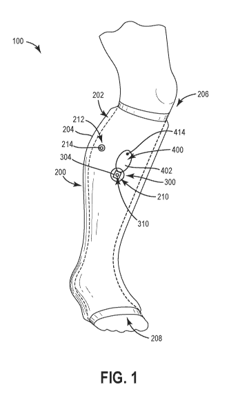
[0021] FIG. 1 is a front perspective view of a negative pressure therapy
garment, according
to an exemplary embodiment.
-4-
CA 03134775 2021-09-23
WO 2020/205329 PCT/US2020/024416
[0022] FIG. 2 is a front view of a control module and a pump module of a
negative pressure
therapy garment, according to an exemplary embodiment.
[0023] FIG. 3 is a side cross-sectional view of a pump module of a negative
pressure therapy
garment, according to an exemplary embodiment.
[0024] FIG. 4 is a schematic diagram of an electrical circuit of a negative
pressure therapy
garment, according to an exemplary embodiment.
[0025] FIG. 5 is an operational schematic of a negative pressure therapy
garment, according
to an exemplary embodiment.
[0026] FIG. 6 is a block diagram showing a method of making a negative
pressure therapy
garment, according to an exemplary embodiment.
DETAILED DESCRIPTION
Overview
[0027] Referring generally to the FIGURES, a garment for applying negative
pressure to
injured limbs and/or joints is provided, according to various exemplary
embodiments. The
garment includes a cover configured to seal off an enclosed region between the
cover and the
limb or joint, for example by sealably engaging with a user's skin or tissue.
The garment
includes a micro-pump configured to apply a negative pressure to the enclosed
region. The
pump is fluidly coupled to the enclosed region and also to an environment
outside of the
cover. The garment also includes a control system configured to control the
pump to regulate
a negative pressure within the enclosed region. The garment may be configured
to coordinate
the application of negative pressure with a user's movements, which can,
advantageously,
minimize user discomfort and improve user mobility.
[0028] The garment may be an occlusive limb cover that fully surrounds the
limb or joint.
The cover may include a hollow sleeve configured to receive the limb or joint.
The pump
may be integrated into an outer wall of the hollow sleeve. The pump may be a
compact
micro-pump in order to reduce operational noise.
-5-
CA 03134775 2021-09-23
WO 2020/205329 PCT/US2020/024416
[0029] The control system may include reusable electronic equipment including
a power
source. The control system may be detachably coupled to the cover so that it
may be re-used
with other devices. The control system may be configured to coordinate
operation of the
pump with user movement, for example, by utilizing a mobility sensor that can
determine at
least one of user orientation and degree of movement.
[0030] In some implementations, the control system may be configured to
monitor pump
operation and to modify control parameters to minimize power consumption.
Feedback to the
control system, based on pump operational information and sensor data, may
also be utilized
to maximize the effectiveness of the treatment. For example, the data may be
transmitted to a
user interface from which a user may monitor treatment progress. These and
other features
and advantages of the garment are described in detail below.
Garment Construction
[0031] Referring now to FIG. 1, a garment 100 is shown, according to an
exemplary
embodiment. The garment 100 includes a cover 200 configured to receive a
person's limb or
joint. As shown in FIG. 1, the cover 200 is configured to receive a portion of
a person's leg,
including a lower portion of the leg and a foot. The cover 200 is configured
to substantially
surround the leg, forming an enclosed region 202 between the cover 200 and the
leg. As
shown in FIG. 1, the cover 200 is configured to sealably engage with the leg
to prevent air
from entering or leaving the enclosed region 202. In the embodiment of FIG. 1,
an upper end
of the cover 200 is configured to seal against a person's skin below the knee.
A lower end of
the cover 200 is configured to seal against the person's foot just above their
toes.
[0032] As shown in FIG. 1, the garment 100 includes a pump module 300 and a
control
module 400 coupled thereto. The pump module 300 includes a pump 302 configured
to
remove air from the enclosed region 202. As shown in FIG. 1, the pump 302 is
disposed in
the cover 200, in an opening in a lower leg portion of the cover 200. As shown
in FIG. 1, the
pump 302 fluidly couples the enclosed region 202 to an environment surrounding
the cover
200 (e.g., external to the cover 200, etc.).
-6-
CA 03134775 2021-09-23
WO 2020/205329 PCT/US2020/024416
[0033] In some implementations, the pump module 300 is configured to regulate
a pressure
of the enclosed region 202. According to an exemplary embodiment, the pump
module 300
includes an electro-mechanical pressure switch operably coupled to the pump
302. The
switch may be configured to complete an electrical connection to the pump 302
when the
pressure within the enclosed region 202 exceeds a threshold value. In some
embodiments, the
pump module 300 includes additional sensors. The sensors may be configured to
monitor
conditions (e.g., temperature, pressure, humidity, etc.) in the enclosed
region 202 or external
to the cover 200. Alternatively, the sensors may be mobility sensors (e.g.,
accelerometers,
etc.) configured to measure mobility data (e.g., angular orientation, degree
of movement,
etc.).
[0034] As shown in FIG. 1, the garment 100 includes a control module 400. The
control
module 400 is configured to control the pump 302 and to regulate a negative
pressure within
the enclosed region 202 between the cover 200 and the leg. As referred to
herein, negative
pressure refers to negative relative pressure referenced to atmospheric
conditions, or reduced
absolute pressure (e.g., a pressure less than 101.3 kPa absolute pressure,
etc.).
[0035] The control module 400 includes electronic equipment including a power
source and a
pump driver or waveform driver. In some embodiments, the control module 400
include a
processing circuit configured to receive and interpret sensor data. The
processing circuit may
be configured to determine whether a user is moving or at rest, a leak rate of
air from the
enclosed region 202, heath/diagnostic data from the pump or sensors, and/or
other processing
functions. The processing circuit may be configured to control the pump based
on sensor data
to optimize the performance of the garment 100.
[0036] In some embodiments, the processing circuit may be configured to
coordinate the
application of negative pressure with user movement. For example, the
processing circuit
may be configured to maintain an increased negative pressure based on a
determination that
the user is at rest and/or to maintain a decreased negative pressure based on
a determination
that the user is moving. Among other benefits, coordinating the application of
negative
pressure with movement improves mobility and reduces user discomfort.
-7-
CA 03134775 2021-09-23
WO 2020/205329 PCT/US2020/024416
[0037] According to an exemplary embodiment, the garment 100 includes a power
monitoring system configured to measure the current drain from the power
source and to
determine when the pump is operational and/or when steady-state conditions
have been
achieved in the enclosed region 202. In some implementations, the power
monitoring system
includes the processing circuit. The power monitoring system may be configured
to
periodically activate the pump in order to maintain a negative pressure within
a suitable
range. The power monitoring system may include an ammeter configured to
measure current
drain on the power source while the pump is operational. The current data may
be utilized to
determine a leak rate of air from the enclosed region. The power monitoring
system may be
configured to control the frequency of pump operation in response to the leak
rate to
minimize pump operation and overall power consumption.
[0038] The control module 400 may include a user interface configured to
receive and
display sensor data, an operating status of the garment 100, or
alerts/notifications generated
by the processing circuit. According to an exemplary embodiment, the control
module 400 is
communicatively coupled to a user device (e.g., a smart device, a mobile
phone, a tablet, a
laptop, or another remote computing device). The control module 400 may be
configured to
transmit sensor data to the user device so that a user may monitor treatment
progress. The
sensor data may be monitored and manipulated from an application on the user
device. In
some implementations, the control module 400 may be configured to transmit
notifications
and alerts to the user device (e.g., notifying the user of a malfunction with
the device, a
sudden loss of negative pressure, etc.). Additionally, the control module 400
may be
configured to receive pump operating commands from the user device and/or
information
about a user's activities (e.g., whether the user is at rest or moving, etc.).
Among other
benefits, interactive control and monitoring of the garment 100 may be used to
assist with
future healing cycles of repetitive injuries to limbs or joints.
[0039] In the embodiment of FIG. 1, the control module 400 is detachably
coupled to the
cover 200. The control module 400 is detachably coupled to a cover-mounted
connector 304
of the pump module 300. Among other benefits, using removable components
reduces
replacement costs for the garment 100, as the control module 400 may be
replaced separately
from the other components.
-8-
CA 03134775 2021-09-23
WO 2020/205329 PCT/US2020/024416
Cover
[0040] An exemplary embodiment of a cover 200 for the garment 100 is shown in
FIG. 1.
The cover 200 includes an outer wall 204 defining a hollow sleeve. The cover
200 is
configured to receive a person's limb or joint such that it substantially
surrounds the limb or
joint. In the embodiment of FIG. 1, the cover 200 is configured to receive a
lower leg portion
and a foot portion of a person's leg. In other embodiments, the cover 200 may
be configured
to receive a person's arm. In yet other embodiments, the cover 200 may be
configured to
receive a swollen joint such as a knee or elbow.
[0041] According to an exemplary embodiment, the cover 200 is configured to
sealably
engage with a person's limb or joint to prevent air from entering or leaving
the enclosed
region 202. As shown in FIG. 1, a first end 206 (e.g., upper end) of the cover
200 is engaged
with a person's skin, just below their knee. The first end 206 includes a cuff
that is engaged
with the skin. The cuff circumferentially surrounds the leg to form an air-
tight seal between
the enclosed region 202 and the surrounding environment. In some embodiments,
the cuff
includes a long or short stretch material that maintains compression between
the cuff and the
skin. As shown in FIG. 1, a second end 208 (e.g., lower end) of the cover 200
is engaged with
the skin just above a person's toes. In the embodiment of FIG. 1, the second
end 208 of the
cover 200 also includes a cuff In alternative embodiments, the second end 208
encloses an
end of a person's foot.
[0042] The cover 200 may include a variety of compressive/expansive materials
including
plastics such as polyvinyl chloride and other materials. According to an
exemplary
embodiment, the cover 200 includes a material with low gas permeability (e.g.,
low gas
transmission rates, etc.) to ensure an air-tight seal between the cover 200
and the leg. In some
implementations, the cover 200 may include an occlusive dressing. The cover
200 may
include a waxy coating and/or silicon adhesive to improve sealing between the
enclosed
region 202 and the surrounding environment. In some implementations, the cover
200 also
includes an inexpensive wound pad, within the enclosed region, along an inner
surface of the
cover, to absorb moisture from the skin. According to an exemplary embodiment,
the cover
200 is configured to be disposed of after use.
-9-
CA 03134775 2021-09-23
WO 2020/205329 PCT/US2020/024416
[0043] As shown in FIG. 1, a central portion of the cover 200, between the
first end 206 and
the second end 208 is loose fitting around the leg both for user comfort and
to ensure that
trapped air along the length of the leg can be transported easily to the pump.
The cover 200
fits snugly around the leg when operational and may be easily hidden beneath a
user's
clothing, if desired, to conceal the device.
[0044] The cover 200 is configured receive pneumatic components of the garment
100. As
shown in FIG. 1, the cover 200 includes a first opening 210 configured to
receive the pump
302, a pressure switch, and the cover-mounted connector 304. The cover 200
also includes a
second opening 212 configured to receive a valve 214. The valve may be one, or
a
combination of, an over-pressure relief valve (e.g., a mechanical pop-off
valve), a manually
actuated pressure release valve, or another type of valve. The cover 200 may
include
additional or fewer openings in various alternative embodiments.
[0045] In some embodiments, the cover 200 includes one or more connectors
(e.g., electrical
connectors) configured to couple (e.g., electrically connect) the electrical
equipment (e.g., the
pump, one or more sensors, etc.) to the cover 200 and/or to position the
electrical equipment
within the cover 200. The connectors may be one, or a combination of, of a
variety of
different connectors known to those of ordinary skill in the art.
Pump Module
[0046] Referring now to FIGS. 1-4, a pump module 300 is shown, according to an
exemplary
embodiment. As shown in FIGS. 1-4, the pump module 300 includes a pump 302 and
a
cover-mounted connector, shown as connector 304. As shown in FIG. 2, the
connector 304 is
configured to operably couple the control module 400 to the pump module 300.
[0047] As shown in FIGS. 1-2, the connector 304 is coupled to the cover 200.
In the
exemplary embodiment of FIG. 1, the connector 304 is disposed within the first
opening 210
of the cover 200 along an upper portion of the leg such that the pump module
300 may be
easily accessed without limiting user mobility. As shown in FIGS. 1-2, the
connector 304 is
sealably coupled to the first opening 210 along a perimeter of the cover-
mounted connector
304. The connector 304 may be coupled to the cover 200 using an adhesive
product such as a
-10-
CA 03134775 2021-09-23
WO 2020/205329 PCT/US2020/024416
silicon adhesive or another air-tight adhesive. In some embodiments, the cover
200 may be
bonded directly (e.g., heat bonded) to the connector 304.
[0048] As shown in FIG. 2, the connector 304 includes a pair of leads 306
(e.g., electrical
leads, terminals, etc.) configured to electrically couple the control module
400 to the pump
module 300. According to an exemplary embodiment, the leads 306 are configured
to power
the pump. The leads 306 may also be configured to power one or more sensors
that are
included as part of the pump module 300. As shown in FIG. 2, the connector 304
also
includes a plurality of mechanical latching points 308 configured to
detachably couple the
control module 400 to the pump module 300. The mechanical latching points 308
may
include clips, tabs, or another form of mechanical connector. The mechanical
latching points
308 may be configured to engage with a pair of sprung connectors or another
mating
connector on the control module 400. In other embodiments, the mechanical
latching points
308 may include another form of detachable mechanical connector.
[0049] The pump 302 is configured to remove air from the enclosed region 202
(e.g., to
transport air from the enclosed region 202, between the cover 200 and the leg
(see also FIG.
1), to the surroundings, etc.). According to an exemplary embodiment, the pump
302 is
disposable. A variety of low cost, quiet, and compact air pumps may be
incorporated into the
garment 100. According to an exemplary embodiment, the pump 302 is a micropump
or
microblower such as a Murata air pump.
[0050] As shown in FIG. 3, the pump 302 is coupled to and contained
substantially within
the connector 304. According to an exemplary embodiment, the pump 302 is
coupled to the
connector 304 along an inner surface of the connector 304. The pump 302 may be
bonded,
glued, or otherwise affixed to the inner surface of the connector 304. An
outer surface of the
connector 304, opposite the inner surface, is coupled to the cover 200. As
shown in FIG. 3,
the pump 302 is disposed proximate to a first end of the connector 304,
adjacent to the
enclosed region 202. An exhaust port 310 is centrally disposed at a second end
of the
connector 304. The size and shape of the connector 304 may be different in
various
alternative embodiments.
-11-
CA 03134775 2021-09-23
WO 2020/205329 PCT/US2020/024416
[0051] As shown in FIG. 3, the pump module 300 includes two filters, a
charcoal filter 312
configured to minimize odors escaping from the enclosed region 202, and a
hydrophobic
filter 314 configured to prevent fluid ingress from the surroundings into the
pump 302 and
the enclosed region 202. In other embodiments, the number and/or arrangement
of filters
within the connector 304 may be different. As shown in FIG. 3, both the
charcoal filter 312
and the hydrophobic filter 314 are disposed within the connector 304,
downstream of the
pump 302, between the pump 302 and an exhaust port of the connector 304.
According to an
exemplary embodiment, the hydrophobic filter 314 is disposed proximate to the
second end
of the connector 304 which may, advantageously, prevent fluid ingress through
the exhaust
port 310 to both the charcoal filter 312 and the pump 302.
[0052] As shown in FIG. 3, the pump module 300 includes a valve 318 disposed
proximate
to the second end of the connector 304, between the hydrophobic filter 314 and
the exhaust
port 310. In some embodiments, the valve 318 is a one-way check valve to
prevent air from
leaking into the enclosed region 202 when the pump 302 is non-operational.
Alternatively,
the valve 318 may be a solenoid valve operably coupled to the control module
400. In yet
other embodiments, the valve 318 may include a manual control button disposed
on an outer
surface of the connector. The control button may include a spring that biases
the button into a
closed position to prevent inadvertent loss of negative pressure. The button
may provide a
functionality by which a user may decrease the negative pressure in the
enclosed region 202
(e.g., increase the absolute pressure) to improve user comfort during periods
of mobility.
[0053] The garment 100 is configured to maintain a negative pressure within
the enclosed
region 202. As shown in FIG. 3, the pump module 300 includes a sensor 316
coupled to the
connector 304 and extending at least partially into the enclosed region 202.
The sensor 316 is
configured to measure a condition of the enclosed region 202. The sensor 316
may be one of
a temperature sensor configured to measure a temperature of the enclosed
region, a humidity
sensor configured to measure a moister level of the enclosed region, a
mobility sensor such as
an accelerometer configured to measure user movement or a user's orientation,
a pH sensor
configured to measure a pH of a user's skin, or another type of sensor.
-12-
CA 03134775 2021-09-23
WO 2020/205329 PCT/US2020/024416
[0054] According to an exemplary embodiment, the sensor 316 is a pressure
sensor
configured to measure a pressure of the enclosed region 202. In the embodiment
of FIG. 3,
the sensor 316 includes an electro-mechanical pressure switch operably coupled
(e.g.,
electrically connected to) to the pump 302, in series between the pump 302 and
a power
source (see also FIG. 4). The electro-mechanical pressure switch is configured
to electrically
couple the pump to a power source in response to the pressure exceeding a
threshold value.
The electro-mechanical switch may be biased by a spring into a closed
position, so as to
complete the electrical circuit between the pump 302 and the power source,
when a pressure
in the enclosed region 202 exceeds a threshold value. The threshold value may
be determined
based on a known therapeutic value of pressure or a range of pressures.
[0055] According to an exemplary embodiment, the electro-mechanical switch is
configured
to maintain a pressure within the enclosed region of approximately negative
125 mm Hg
(e.g., -16.7 kPa relative pressure, 84.7 kPa absolute pressure), in a range
between
approximately negative 105 mm Hg and negative 145 mm Hg (e.g., a threshold
value of
approximately negative 105 mm Hg), or another suitable range of pressures
based on the type
of injury and its severity. In some implementations, the switch may further
include an
absorber component (e.g., a closed cell foam, padding, or another absorber) in
order to
dampen hysteresis and prevent sensor "flutter," or to prevent the switch from
alternating
rapidly between an open and closed position when the pressure is approximately
equal to the
threshold value.
Control Module
[0056] According to an exemplary embodiment, the garment 100 includes a
control system
configured to control the pump 302 and to regulate a negative pressure within
the enclosed
region 202. As shown in FIGS. 1-2, the control system includes a control
module 400. The
control module 400 includes a housing 402 configured to detachably couple the
control
module 400 to the pump module 300. The control module 400 includes a plurality
of reusable
electronic equipment for the garment 100. The equipment is contained
substantially within
the housing 402, which prevents water damage and provides an improved overall
aesthetic
appearance.
-13-
CA 03134775 2021-09-23
WO 2020/205329 PCT/US2020/024416
[0057] As shown in FIGS. 1-2, the housing 402 includes sprung connectors 404
that engage
with the mechanical latching points 308 on the cover-mounted connector 304.
The sprung
connectors 404 may include metal clips, latches, or another form of mechanical
connector. In
some embodiments, the sprung connectors 404 also function as electrical
connectors
configured to engage with the leads 306 on the cover-mounted connector 304.
[0058] In some embodiments, the control module 400 is configured to identify
whether the
control module 400 is correctly connected to the pump module 300 (e.g., that
the control
module 400 is properly aligned with the pump module 300, that the control
module 400 has
fully engaged with the mechanical latching points 308, that an electrical
connection has been
established between the pump module 300 and the control module 400, etc.). The
control
module 400 may include a read switch or magnetic sensor structured to trigger
an alarm if the
control module 400 and the pump module 300 are misaligned. For example, the
control
module 400 may include a magnetic sensor integrated centrally between the
sprung
connectors 404. The pump module 300 may include an opposing magnet integrated
into the
cover-mounted connector 304. In some implementations, the opposing magnet may
be
integrated into the connector 304 proximate to the mechanical latching points
308. In the
event the magnetic sensor isn't fully aligned with the magnet (e.g., in the
event the control
module 400 is detached from the pump module 300, etc.), the control module 400
may be
configured to generate a notification alerting a user of misalignment. The
notification may be
an audible alarm, a visual notification (e.g., a light), a notification on a
user's phone or smart
device, or another suitable notification.
[0059] In some embodiments, the garment 100 is configured to prevent
unauthorized or
unintentional removal of the control module 400 from the pump module 300. For
example,
the connector 304 may include a locking member including a solenoid latch that
prevents
separation of the control module 400 from the connector 304 until a release
command is
received from a user device. The release command may be generated by entering
a personal
identification number or password into an application on the user device.
Different
controllable locking mechanisms may be utilized in various alternative
embodiments. In
some embodiments, the garment 100 includes an ultraviolet (UV) switching
adhesive system
to prevent unauthorized separation of the control module 400 from the pump
module 300.
-14-
CA 03134775 2021-09-23
WO 2020/205329 PCT/US2020/024416
The control module 400 may include a UV switching adhesive disposed proximate
to the
sprung connectors 404. The UV switching adhesive may be configured to adhere
to the
cover-mounted connector 304 in the absence of a light source. The pump module
300 may
include an emitter (e.g., a UV light source, etc.) disposed on the cover-
mounted connector
304 and configured to release the adhesive from the cover-mounted connector
304 upon
receipt of the release command from the user device.
[0060] Referring now to FIG. 4, a schematic diagram of a circuit 500 for the
garment 100 is
shown, according to an exemplary embodiment. The garment 100 includes a
plurality of
electrical components configured to control the pump 302 and regulate a
negative pressure
within the enclosed region 202. In alternative embodiments, the control module
400 may
include additional, fewer, and/or different components. As shown in FIG. 4,
the circuit 500 is
subdivided into two portions, a first portion 502 including electrical
components for the pump
module 300, and a second portion 504 including electrical components for the
control module
400. In alternative embodiments, the position of electrical components within
the circuit 500
may be different.
[0061] As shown in FIG. 4, the control module 400 includes a power source 406,
an ammeter
408, memory 410, a transceiver 412, a user interface 414, and a processor 416.
The power
source 406 may include a battery such as a lithium-ion battery, or another
compact or
lightweight battery type. The power source 406 may be rechargeable. In some
embodiments,
the power source 406 may be recharged by separating (e.g., detaching,
removing, etc.) the
control module 400 from the pump module 300 and placing the control module 400
on a
recharging station or otherwise coupling the control module 400 to a wall
outlet. In other
embodiments, the power source 406 may be removably coupled to the control
module 400.
[0062] As shown in FIG. 4, the power source 406 is coupled (e.g., electrically
coupled) to the
pump 302 and a pressure sensor 418 in a series circuit arrangement. The
pressure sensor 418
may be configured to operate the pump 302 substantially independently from the
control
module 400. According to an exemplary embodiment, the pressure sensor 418 is
an electro-
mechanical pressure switch whose position is determined based on the pressure
in the
enclosed region 202 (see also FIG. 1), as was described with reference to
sensor 316 in FIG.
-15-
CA 03134775 2021-09-23
WO 2020/205329 PCT/US2020/024416
3. In other embodiments, the pressure sensor 418 may be a transducer
configured to measure
the pressure (e.g., the negative pressure relative to atmospheric pressure,
etc.) in the enclosed
region 202.
[0063] As shown in FIG. 4, the control module 400 is operably coupled to a
second sensor,
shown as sensor 418. The sensor 420 may be configured similar to sensor 316.
The sensor
420 may be coupled to the cover-mounted connector 304 and extend at least
partially into the
enclosed region 202 so as to measure a condition of the enclosed region 202.
According to an
exemplary embodiment, the sensor 420 is configured to provide information
related to a
user's mobility (e.g., to measure mobility data such as a user's orientation,
degree of
movement, etc.). In some embodiments, the sensor 420 includes an accelerometer
configured
to measure the force and frequency of a user's movements (e.g., each step
taken by a user,
contact between a user's foot and a ground surface, or another force
associated with user
movement). In other embodiments, the sensor 420 includes a heart rate sensor
or another
health monitoring sensor, which could determine user movement based on
increased heart
rate, body temperature, skin moisture (e.g., perspiration), and other factors.
[0064] As shown in FIG. 4, the control module 400 is operably coupled to a
valve 422. The
valve 422 may be the same as valve 214 described with reference to FIG. 1 or
valve 318
described with reference to FIG. 2. According to an exemplary embodiment, the
valve 422 is
a solenoid valve configured to allow air to enter the enclosed region 202 (see
also FIG. 1) in
response to a control signal generated by the control module 400. The control
module 400
may be configured to open the valve 422 based on a determination that the user
is moving in
order to reduce pain and discomfort, or in response to a command from a user
device
indicating that the user is at rest (e.g., that the user is immobile, etc.).
[0065] The control module 400 includes a power monitoring system. The power
monitoring
system is configured to monitor and optimize pump 302 operation. The power
monitoring
system includes an ammeter 408 configured to measure an amount of current
provided to the
pump 302 by the power source 406. The ammeter 408 may include one of a variety
of
commercial current measurement devices known to those of ordinary skill in the
art. As
shown in FIG. 4, the ammeter 408 is integrated in a series circuit arrangement
between the
-16-
CA 03134775 2021-09-23
WO 2020/205329
PCT/US2020/024416
power source 406 and the pump 302. In other embodiments, the location of the
ammeter 408
within the circuit 500 may be different.
[0066] Memory 410 for the control module 400 may be configured to store
operating
instructions for the garment 100. Memory 410 may also be configured to store
control
parameters. The control parameters may include a threshold value of pressure
for the
enclosed region 202. The threshold value of pressure may be a therapeutic
pressure or range
of pressures shown to facilitate healing or wound recovery. The threshold
value of pressure
may vary based on the type of injury, progress of treatment, and other
factors. According to
an exemplary embodiment, the control parameters include threshold values for
the power
management system. For example, the control parameters may include threshold
values of
current supplied to the pump 302 and below which the pump 302 should be
deactivated. The
control parameters may additionally include a cycling frequency for the pump
302 and a
threshold rate of change of current between cycles.
[0067] The transceiver 412 may include a transmitter for transmitting
information and/or a
receiver for receiving information. According to an illustrative embodiment,
the transceiver
412 is configured to communicate wirelessly with a user device (e.g., via Wi-
Fi, Bluetooth,
or another suitable wireless communication protocol). The user device may
include a remote
computing device such as a smart watch, a mobile phone, a laptop computer, a
tablet, an
internet of things (IoT) device, or another internet or network connected
device. The
transceiver 412 may be configured to transmit sensor data from at least one of
the sensors
316, 420 to the user device. The sensor data may include at least one of
temperature data,
humidity data, pressure data, mobility data, and pH data. The sensor data may
be accessed
through an application on the user device. The application may be configured
to provide
guidance or a treatment regimen to a user of the garment 100 in order to
maximize the
effectiveness of the treatment.
[0068] According to an exemplary embodiment, the application is configured to
tailor (e.g.,
adjust, modify, etc.) the treatment regimen based on sensor data. Sensor data
provided to the
user device throughout a healing cycle may also be utilized to optimize future
healing cycles
of repetitive injuries to the same limb, joint, or muscle group. For example,
the user or the
-17-
CA 03134775 2021-09-23
WO 2020/205329 PCT/US2020/024416
control system may identify a progression of movement (e.g., a rate of
increase in user
mobility over the treatment duration) that is optimal for recovery by
comparing
improvements in pain, wound appearance, heat measurements of tissues, and
measured
parameters with increases in the rate of mobility over the treatment period.
Moreover, the
application may be configured to share treatment information (e.g., through
the cloud or
between user devices) with others having similar injuries. The application may
allow the user
to compare healing times and rest-exercise regimens in order to further
optimize the
therapeutic benefits of the treatment (e.g., so that a user may learn and
adapt their treatment
style, so that the application may adapt its prescribed treatment regimen,
etc.).
[0069] The transceiver 412 may also be configured to transmit notifications to
the user
device. For example, the transceiver 412 may be configured to transmit a
notification to the
user device alerting the user that they should rest to reduce the risk of
further injury. The
transceiver 412 may also be configured to transmit diagnostic data from one or
more sensors
316, 420 to the user device. The diagnostic data may be health monitoring data
for one or
more sensors 316, 420, notification of a poor connection between the control
module 400 and
the pump module 300, notification of an operational or performance issue
(e.g., issues with
achieving a desired negative pressure within the enclosed region 202 (see also
FIG. 1), etc.).
The notification may be a text message or an application pop-up on the user
device.
Alternatively, the notification may be an audible or visual alert generated by
the user
interface 414.
[0070] According to an exemplary embodiment, the user interface 414 is
configured to
generate and display notifications and alerts. As shown in FIGS. 1-2, the user
interface 414
includes an indicator 424 configured to report a condition of the enclosed
region 202 or an
operating condition or status of the garment 100. As shown in FIGS. 1-2, the
indicator 424
includes a light emitting diode (LED) disposed on an outer surface of the
housing 402.
According to an exemplary embodiment, the indicator 424 is configured to
provide a visual
indication of an operating status to a user. The operating status may include
remaining battery
life, an operating status of the pump 302, an indication of alignment between
the control
module 400 and the pump module 300, etc. In other embodiments, the indicator
424 may
-18-
CA 03134775 2021-09-23
WO 2020/205329 PCT/US2020/024416
include a speaker, an LED display, or another type of indicator known to those
of ordinary
skill in the art.
[0071] As shown in FIG. 4, the control module 400 includes a processing
circuit, shown as
processor 416. The processor 416 may be operably coupled each of the
components in the
control module 400 and configured to control interaction between the
components. According
to an exemplary embodiment, the processor 416 is configured to receive and
interpret
mobility data from the sensor 420. In some embodiments, the processor 416 may
be
configured to generate a control signal for at least one of the pump 302 and
the valve 422
based on the mobility data from the sensor 420. The processor 416 may form
part of the
power management system and may be configured to control the pump 302 to
minimize
power consumption. The function of the processor 416 will be described in
further detail with
reference to FIG. 5.
Pump Operation
[0072] Referring now to FIG. 5, a method 600 of operating the pump 302 (see
also FIG. 1) is
shown, according to an exemplary embodiment. The method 600 includes
activating the
power source 602 for the garment 100. The power source 406 may be activated by
connecting
the control module 400 to the pump module 300 or by actuating an on/off switch
for the
garment 100 after the control module 400 and the pump module 300 have been
connected
(e.g., aligned or otherwise connected).
[0073] The control module 400 is configured to coordinate the application of
negative
pressure to the enclosed region 202 with a user's movements. More
specifically, the control
module 400 is configured to maintain an increased negative pressure within the
enclosed
region 202 when the user is at rest and to maintain a decreased negative
pressure within the
enclosed region 202 when the user is moving. As shown in FIG. 5, the method
600 includes
using the sensor 420 to control operation of the pump 302. The method 600
includes querying
the sensor 604 to determine if the user is at rest 606. The sensor 420 may be
configured to
output sensor data indicative of user movement (e.g., a pulse, a voltage,
etc.). The processor
416 may be configured to receive the sensor data and to identify a period of
time (e.g., by
querying a timer) between user movements. The processor 416 may be configured
to
-19-
CA 03134775 2021-09-23
WO 2020/205329 PCT/US2020/024416
compare the period of time with a threshold period of time stored in memory
410.
Alternatively, the processor 416 may be configured to identify that the user
is at rest based on
a command received from the user device.
[0074] As shown in FIG. 5, the method 600 includes controlling the pump 302 to
maintain an
increased negative pressure 608 in the enclosed region 202 based on a
determination that the
user is at rest. According to an exemplary embodiment, the processor 416 is
configured to
generate a control signal that causes the pump 302 (e.g., to a pump driver,
waveform driver,
etc.) to increase the negative pressure in the enclosed region 202 (e.g., to
decrease the
absolute pressure in the enclosed region). The processor 416 may maintain an
increased
negative pressure by at least one of activating the pump 302, increasing an
operating speed of
the pump 302, and closing a valve 318, 422.
[0075] The method 600 further includes controlling the pump 302 to decrease
and maintain a
decreased negative pressure 610 in the enclosed region 202 based on a
determination that the
user is moving. According to an exemplary embodiment, the processor 416 is
configured to
generate a control signal that causes the pump 302 to decrease the negative
pressure in the
enclosed region 202 (e.g., to increase the absolute pressure in the enclosed
region 202). The
processor 416 may maintain the decreased negative pressure by at least one of
deactivating
the pump 302, reducing an operating speed of the pump 302, and opening a valve
422. In
some implementations, the garment 100 may be configured to allow the pressure
to decay
naturally through patient movement and application leak to a lower pressure
(e.g., -50 mm
Hg or another suitable pressure) in order to reduce discomfort during periods
of ambulation.
The control module 400 may be configured to continuously query the sensor 420
to
determine changes in the user's mobility. Alternatively, the control module
400 may be
configured to reassert negative pressure to the enclosed region 202 after a
given period of
time has elapsed.
[0076] The method 600 includes controlling the pump 302 to regulate the
pressure of the
enclosed region 202 (see also FIG. 1) and to reduce power consumption. As
shown in FIG. 5,
the method 600 includes activating the pump 612. According to an exemplary
embodiment,
the processor 416 is configured to activate and deactivate the pump 302 at a
first cycling
-20-
CA 03134775 2021-09-23
WO 2020/205329 PCT/US2020/024416
frequency stored in memory 410. For example, the processor 416 may be
configured to pole
(e.g., to activate the pump 302, increase the operating speed of the pump 302,
etc.) every 3
min., 6 min., or another suitable cycling frequency. The cycling frequency may
vary
depending on injury type, pressure requirements, and/or progression of
treatment.
[0077] The method 600 may include monitoring the current drain during pump 302
operation
(e.g., at the cycling frequency) using the power monitoring system. According
to an
exemplary embodiment, the processor 416 is configured to continue operating
the pump 302
until the amount of current is below a threshold current value. More
specifically, the
processor 416 is configured to continue operating the pump 302 until at least
one of two
conditions have been achieved. A first condition includes operating the pump
302
continuously until the measured current drain (e.g., the current measured
using ammeter 408)
is less than or equal to approximately 80% or another fraction of the full-
load operating
current. A second condition includes operating the pump 302 continuously until
the measured
current drain is less than or equal to approximately 80% of the close-coupled
current draw of
the pump 302 (e.g., the anticipated close-coupled or full load current draw).
A current draw
below the threshold current indicates that steady-state operating conditions
have been
achieved in the enclosed region 202 (e.g., a largest negative pressure in the
enclosed region
202 has been achieved, etc.). The threshold current value may be different in
various
alternative embodiments.
[0078] As shown in FIG. 5, the method 600 includes storing measured current
data 614 from
the power source 406 (e.g., the measured current drain during periods when the
pump 302 is
operational). According to an exemplary embodiment, the processor 416 is
configured to
receive and store data from the ammeter 408. The processor 416 may be
configured to
determine a rate of change of current during a single operating cycle of the
pump 302 or
between adjacent operating cycles (e.g., at the cycling frequency of the pump
302, etc.). As
shown in FIG. 5, the method 600 includes comparing the measured rate of change
of current
with a threshold rate of change. The method 600 includes reducing the cycling
frequency
618, from the first cycling frequency to a second cycling frequency, based on
a determination
that the measured rate of change is less than the threshold rate of change 616
(e.g., that the
pump 302 does not need to be operated as frequently in order to maintain the
required
-21-
CA 03134775 2021-09-23
WO 2020/205329 PCT/US2020/024416
pressure in the enclosed region 202). Among other benefits, this control
approach minimizes
power consumption over the treatment duration.
[0079] The operations of method 600 are provided for illustrative purposes
only and should
not be considered limiting. Many alternatives are possible without departing
from the
inventive concepts disclosed herein. For example, the method may further
include
quantifying the leak rate from the cover. The leak rate may be quantified
using current
measurements from the ammeter 408, or by examining pressure measurements over
time
from a pressure transducer. Among other benefits, using a pressure transducer
would allow
for a more accurate calculation of leak rate of air into the enclosed region
202 (see also FIG.
1).
Making a Garment for Negative Pressure Therapy
[0080] Referring now to FIG. 6, a method 700 of making a garment for negative
pressure
therapy is shown, according to an exemplary embodiment. In other exemplary
embodiments,
additional, fewer, and/or different operations may be performed. The method
700 includes
providing a cover 702, providing a pump 704, and providing a control system
706. As
described with reference to FIGS. 1-2, the control system 706 includes a
control module 400.
As shown in FIG. 6, the method 700 includes integrating the pump into the
cover 708. In
some embodiments, the pump may be integrated as part of a pump module into the
cover.
According to an exemplary embodiment, the components of the pump module are
made from
inexpensive materials to reduce the cost associated with damaging the cover or
any cover-
mounted component.
[0081] As shown in FIG. 6, the method 700 additionally includes coupling the
control system
to at least one of the cover and the pump 710. The method 700 further includes
electrically
coupling the pump to the control system 712. According to an exemplary
embodiment, the
control module 400 is detachably coupled (e.g., removably coupled) to the pump
module
such that the control module 400 may be reused with different covers.
[0082] The method 700 further includes providing additional electrical
components that
facilitate control and operation of the garment. Operations include providing
a valve 714
-22-
CA 03134775 2021-09-23
WO 2020/205329 PCT/US2020/024416
(e.g., a solenoid valve or a manual discharge valve), a sensor 718 (e.g., an
electro-mechanical
pressure switch, etc.), and a power source 722 (e.g., a battery). The method
700 includes
integrating the valve 716 and the sensor 720 into the cover. The method 700
includes
coupling the power source to the cover 724, and electrically coupling the
sensor to both the
pump and the power source 726.
Configuration of Exemplary Embodiments
[0083] The construction and arrangement of the systems and methods as shown in
the
various exemplary embodiments are illustrative only. Although only a few
embodiments have
been described in detail in this disclosure, many modifications are possible
(e.g., variations in
sizes, dimensions, structures, shapes and proportions of the various elements,
values of
parameters, mounting arrangements, use of materials, colors, orientations,
etc.). For example,
the position of elements can be reversed or otherwise varied and the nature or
number of
discrete elements or positions can be altered or varied. Accordingly, all such
modifications
are intended to be included within the scope of the present disclosure. The
order or sequence
of any process or method steps can be varied or re-sequenced according to
alternative
embodiments. Other substitutions, modifications, changes, and omissions can be
made in the
design, operating conditions and arrangement of the exemplary embodiments
without
departing from the scope of the present disclosure.
-23-